3902
Towards Dense Flexible Transceive Coil Array: Comparison Study of Coaxial Dipoles for 7T Human Torso MRI.1Biomedical Engineering, Kings's College London, London, United Kingdom, 2Electrical Engineering, Technical University of Eindhoven, Eindhoven, Netherlands, 3London Collaborative Ultra high field System (LoCUS), King's College London, London, United Kingdom, 4MR Research Collaborations, Siemens Healthineers, Frimley, United Kingdom
Synopsis
Keywords: RF Arrays & Systems, High-Field MRI
In this work, we explored properties of various coaxial dipole designs and compared them with the conventional dipole. Dipoles were fabricated of RG58 coaxial cable and the total length was 34cm. S-parameters and flip angle maps of individual elements and array configurations were measured on a torso phantom. Comparison of flip angle maps shows very similar performances of all examined dipoles with the coaxial dipole being slightly advantageous. When placed in densely populated array configuration, coaxial dipoles were sufficiently decoupled and produced expected B1+ maps. Coaxial dipole shows promising performances to be used in a densely populated flexible torso array.Introduction
Flexible receive arrays have been utilized widely to image a specific anatomical region and to fit a wide range of patient subjects[1-5]. Dipole and loop designs made of flexible coaxial cables were proposed as transceive array elements[6,7]. They have low sensitivity to bending and superior decoupling properties which makes them suitable for conformal fitting on a subject. For those reasons, we investigated dipole antennas made of coaxial cable, as array elements in flexible dense transceive array for torso imaging at 7T as dipole antenna shows enhanced signal efficiency in depth[8,9] and tight fit design will enhance transmit efficiency. The aim of this work is to investigate the performance of four coaxial dipole designs compared to a conventional dipole individually and in array configuration.Methods
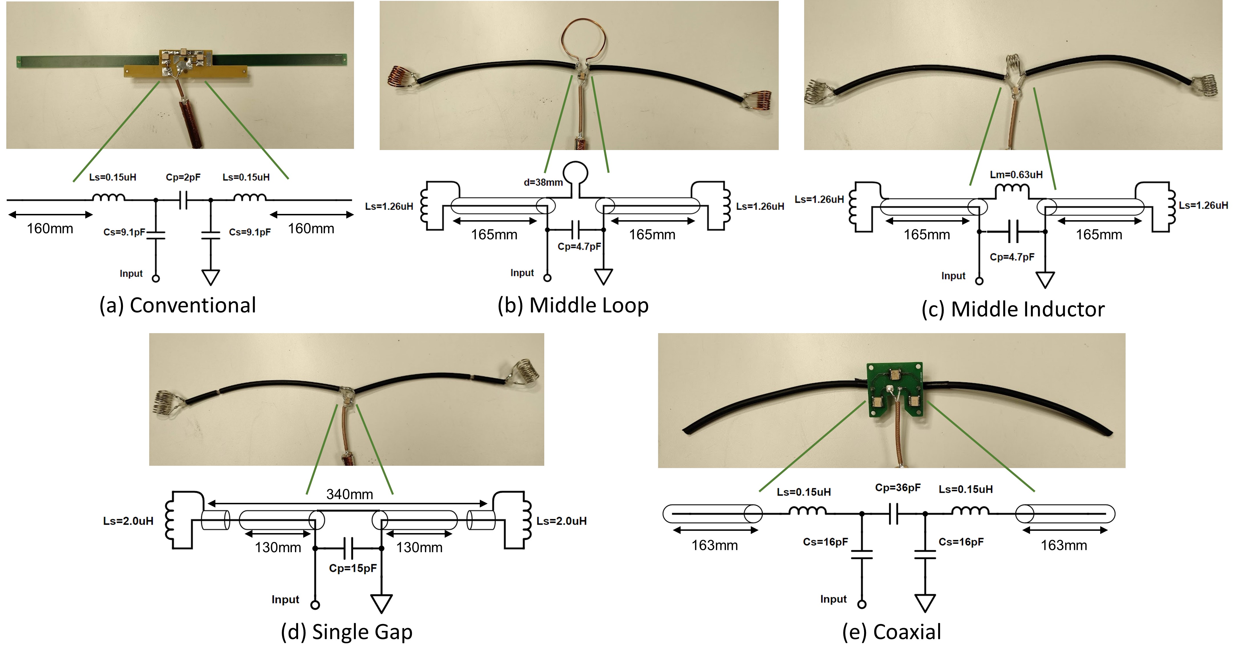
Individual coaxial dipole comparison: Four different types of coaxial dipoles were built (Fig.1) and compared with a conventional dipole (Fig.1(a))[10]. Coaxial dipoles were made of RG-58 coaxial cable (Multicomp Pro, UK) with a total length of 340mm. Fixed capacitors (ATC 100C series, NY) and hand-wound copper wire inductors, were used for tuning and matching to 297.2 MHz at 50 Ohm. All the dipoles were centrally fed by a coaxial cable (K_02252_D, Huber+Suhner, Switzerland) with in-house built baluns tuned to the resonant frequency to limit the interference of the cable.The middle loop dipole (Fig.1(b)) was made with two sections of 165mm-long coaxial cable. At the end of each section the inner conductor and the shield are connected via an inductor. The shields of two sections were connected with a loop 38mm in diameter.
The middle inductor dipole (Fig.1(c)) is the same as the middle loop dipole but with the loop replaced by an inductor.
The single gap dipole (Fig.1(d)), was introduced by Van Leeuwen et. al. [7]. The dipole was made of two sections with a 3mm gap in the shield introduced at each section at 40mm distance from the end of the section. The shields of two sections at the feed point were connected while at the end of each section the inner conductor and the shield are connected via an inductor.
The coaxial dipole (Fig.1(e)) consists of two sections of 163mm coaxial cable. In addition to capacitive matching network, two inductors in series were connected to each section of the antenna.
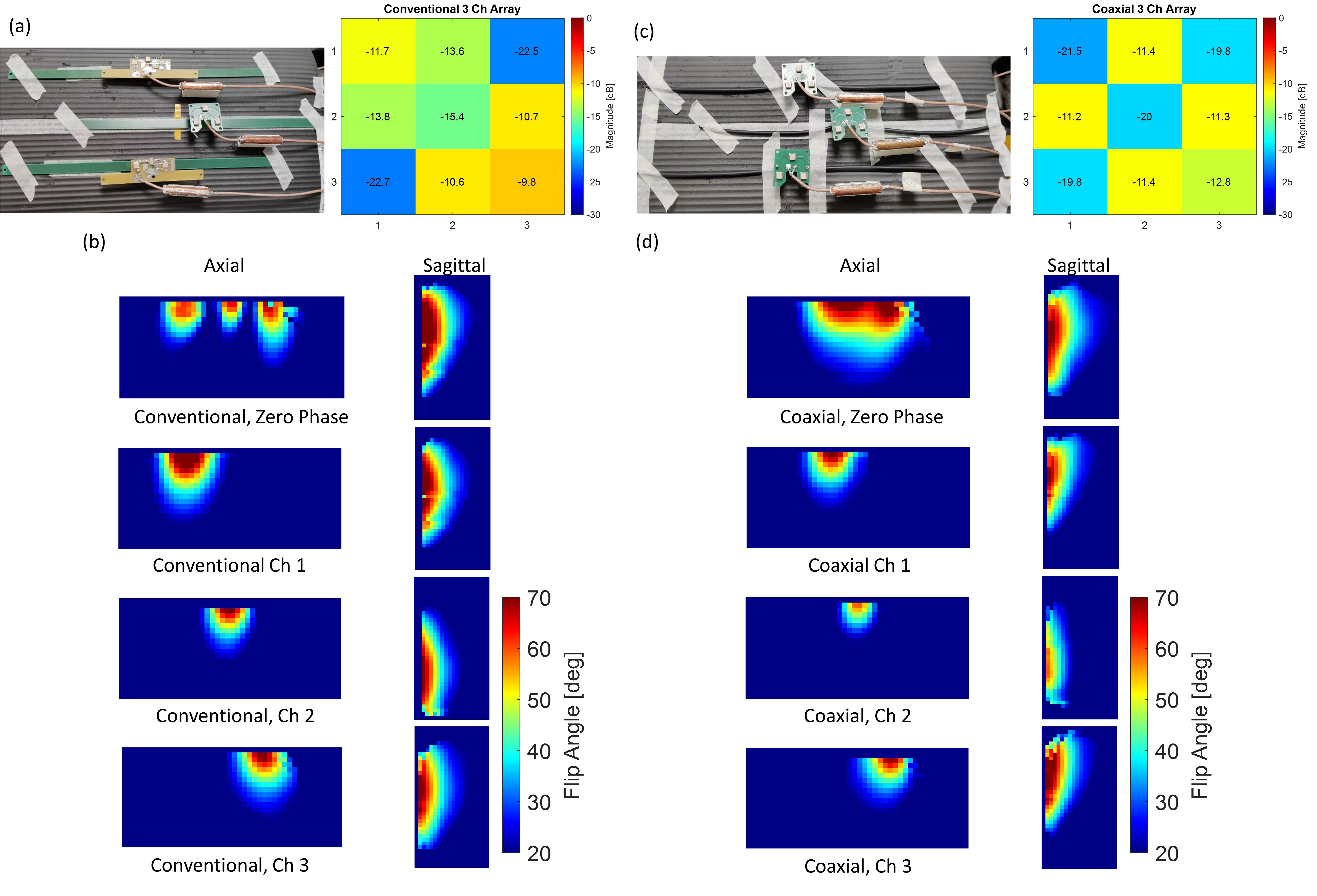
Dense coaxial dipole array comparison: Two arrays containing three dipole elements each were constructed with coaxial (Fig.4(c)) and conventional (Fig.4(a)) dipoles, where each element is 5 cm apart and 7cm vertically shifted (foot-head), covering 41cm in length and 15cm in width.
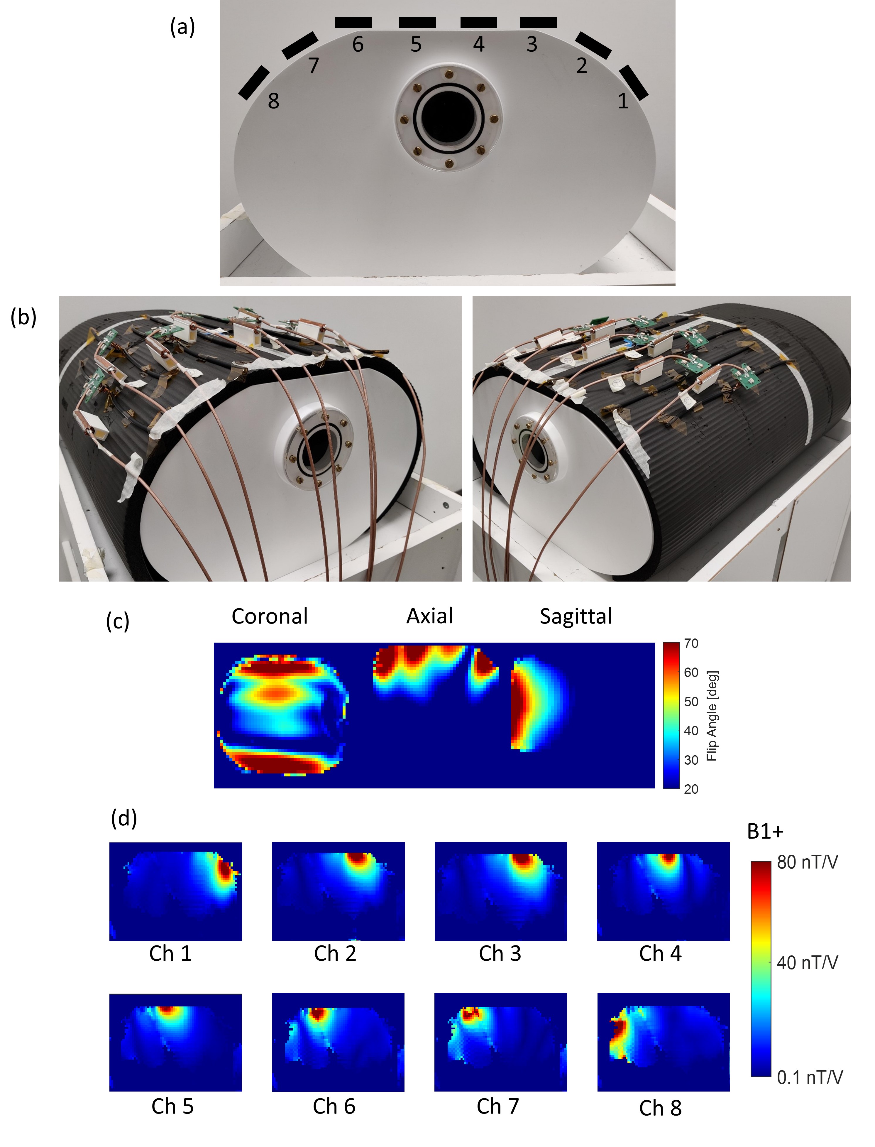
In addition, 8 coaxial dipole array was fabricated and spaced at 5cm distance from each other (Fig.5(a)). The array covers 41cm in length (foot-head) and 34cm in width (anterior-posterior).
Bench and MRI measurement setup: Individual elements and array configurations were designed on a 15mm thick yoga mat placed on in-house designed, 3D-printed (Deed3D, Guangzhou, China) and filled with 35-litre 4% NaCl water solution torso-shaped phantom (42x42x25 cm) for the bench and MRI measurements. S-parameters were measured with VNA (E5063A ENA, Keysight). MR data were acquired on a 7T MR scanner (MAGNETOM Terra, Siemens, Germany). Flip angle/B1+ maps were acquired using the 3D actual-flip-angle method (AFI) (TR=200ms, 8.3x8.3x5.0mm3, FA=60deg, 1 average, 48 slices)[11]. Maps of individual channels on the pTx system were acquired by setting the amplitude of the desired channel to 0.35 while the rest of the channels were set to 0. The phases of individual channels were set to 0.
Results
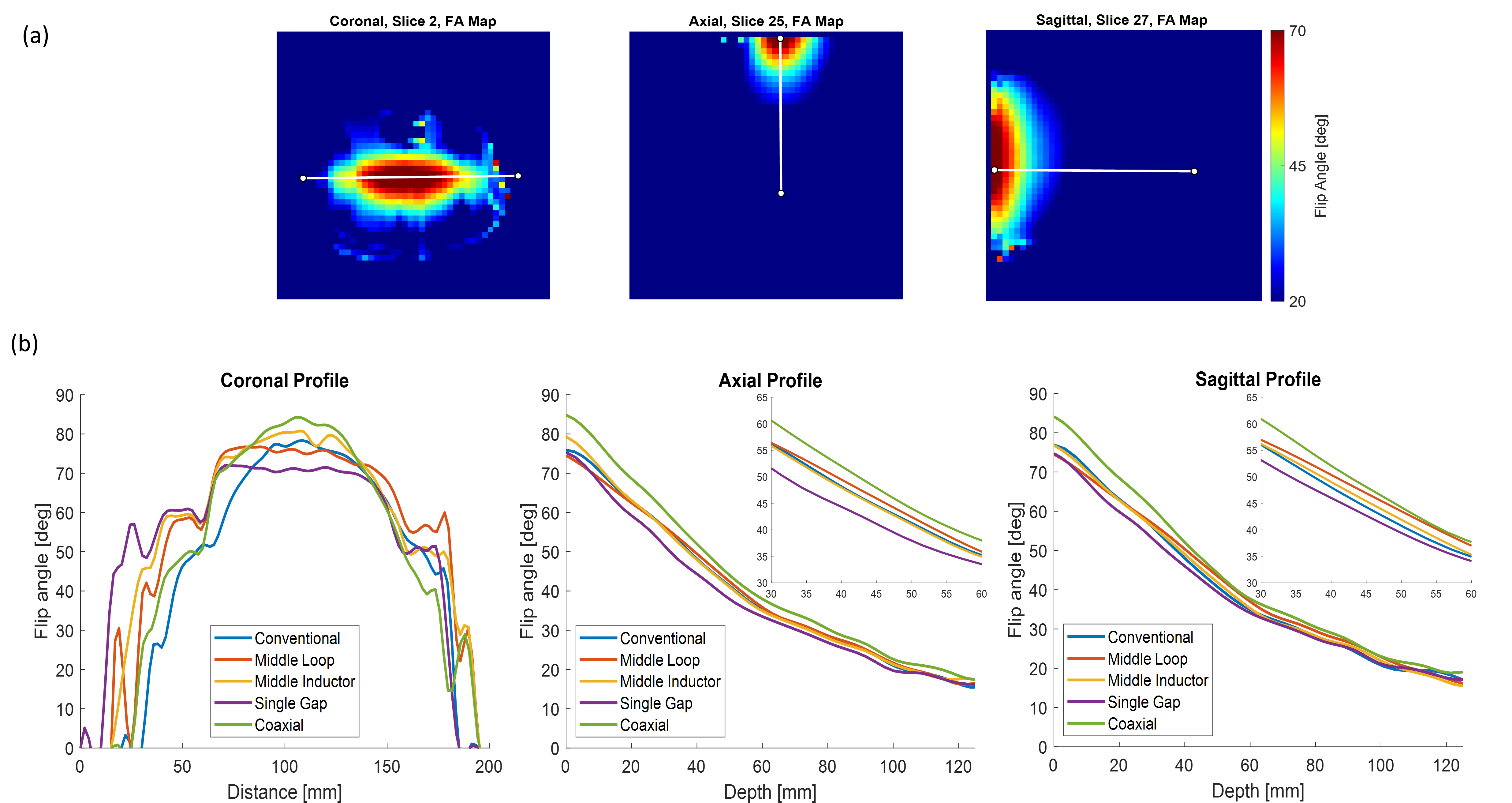
The reflection coefficients of the fabricated dipoles range between -14 to -28dB.Fig.2 shows flip angle (FA) maps of fabricated dipoles. The coaxial dipole (Fig.1e) has the highest FA profiles in the axial and sagittal planes (at 5cm depth 43.1° and 43.8°, respectively) compared to the other dipoles, while the coronal oriented profile is less broad.
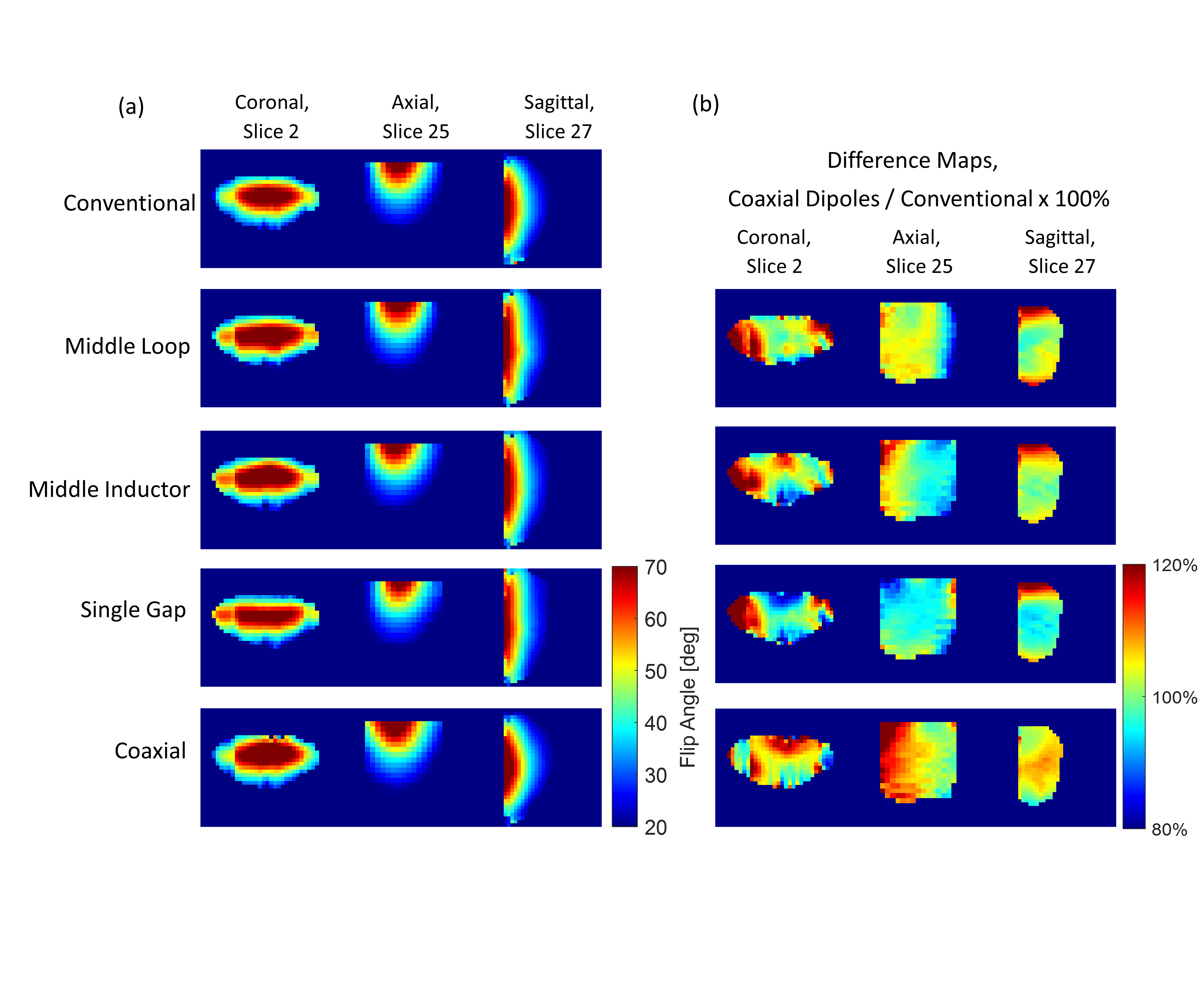
FA and difference maps of the fabricated dipoles are shown in Fig.3. All dipoles have similar performance where the coaxial one slightly outperforms the rest.
Fig.4 shows 3-channel arrays of coaxial and conventional dipoles, their S-matrices and FA maps. S-parameter measurements show better decoupling for the coaxial dipoles. The axial FA map of the full coaxial array shows constructive interference between the elements.
Fig.5 shows the fabricated 8-channel coaxial dipole array, covering the upper half of the body phantom. FA maps of the array with all phases equal to zero as well as individual B1+ maps of the individual elements.
Discussion and Conclusion
In this study, we showed the comparison of 5 dipoles - 4 coaxial dipole designs and one conventional dipole. Flip angle maps of individual elements were measured and no significant difference between the elements was observed, except for the coaxial dipole, which performed slightly better than other dipoles. Studying coupling behaviour showed that the decoupling of coaxial dipoles was better than that of conventional dipoles. The 8-channel array constructed of coaxial dipole elements showed promising performances. Further improvements can be made by finding the optimal balun and cable placement and distance between the elements to get a dense, flexible, torso array. As future work, towards in-vivo imaging, values of maxSAR of the individual elements as well as in array configuration should be investigated.Acknowledgements
This work was supported by core funding from the Wellcome/EPSRC Centre for Medical Engineering [WT203148/Z/16/Z], Wellcome Trust Collaboration in Science grant [WT201526/Z/16/Z] and by the National Institute for Health Research (NIHR) Biomedical Research Centre based at Guy’s and St Thomas’ NHS Foundation Trust and King’s College London and/or the NIHR Clinical Research Facility. The views expressed are those of the author(s) and not necessarily those of the NHS, the NIHR or the Department of Health and Social Care.References
[1] Corea J.R., Flynn A.M., Lechene B., Scott G., Reed G.D. Shin P.J., Lustig M., Aria A.C. Screen-printed flexible MRI receive coils. Nature Communications 2016; 7, 10839. https://doi.org/10.1038/ncomms10839
[2] Grueber B., Rehner R. Laistler L., Zink S. Anatomically adaptive coils for MRI-a 6-channel array for knee imaging at 1.5 Tesla. Front. Phys. 2020 https://doi.org/10.3389/fphy.2020.00080
[3] Port A., Luechinger R., Brunner D.O., Pruessman K.P. Elastomer coils for wearable MR detection. Magn Reson Med 2021; 85, 2882. https://doi.org/10.1002/mrm.28662
[4] Motovilova E., Tan ET., Taracila V., Vincent JM., Grafendorfer T., Shin J., Potter H.G., Robb FJL, Sneag DB., Winkler SA. Strecthable self-tuning MRI receive coils based on liquid metal technology. Scientific reports 2021;11. https://doi.org/10.1038/s41598-021-95335-6
[5] A high-impedance detector-array glove for magnetic resonance imaging of the hand. Nat Biomed Eng. 2018 Aug;2(8):570-577. https://doi.org/10.1038/s41551-018-0233-y
[6] Ruytenberg T., Webb A., Zivkovic I. Shielded-coaxial-cable coils as receive and transceiver array elements for human MRI. Magn MEd 83; 1135-1146. https://doi.org/10.1002/mrm.27964
[7] van Leeuwen CC, Steensma BR, Klomp DWJ, van den Berg CAT, Raaijmakers AJE. Coax Dipole: A fully flexible coaxial cable dipole antenna with flattened current distribution for body imaging at 7 Tesla. Magn Reson Med. 2022;87:528–540. https://doi.org/10.1002/mrm.28983
[8] Raaijmakers AJE, Ipek O., Klomp DWJ., Possanzini C., Harvey PR., Lagendijk JJW., van den Berg CAT. Design of radiative surface coil array element at 7 T: the single-sided adapted dipole antenna. Magn Reson Med. 2011; 66; 1488-1497. https://doi.org/10.1002/mrm.22886
[9] Clement J., Gruetter R. Ipek O. A human cerebral and cerebellar 8-channel transcieve RF dipole coil array at 7T. Magn Reson Med 2019; 81: 1447-1458. https://doi.org/10.1002/mrm.27476
[10] Papoutsis K., Clement J., Ogier SE., Hajnal JV., Goh V., Cook GJ., Ipek O. Construction and characterisation of a 7 Tesla flexible body coil with 10 transmit dipoles and 30 receive loops. ISMRM 2022; 2255. https://submissions.mirasmart.com/ISMRM2022/Itinerary/Files/PDFFiles/2255.html
[11] Yarnykh VL. Actual flip-angle imaging in the pulsed steady state: a method for rapid three-dimensional mapping of the transmitted radiofrequency field. Magn Reson Med. 2007 Jan;57(1):192-200. https://doi.org/10.1002/mrm.21120
Figures