3900
High impedance quadrature receivers array for magnetic resonance skin imaging at 7T1Department of Biomedical Engineering, University at Buffalo, Buffalo, NY, United States
Synopsis
Keywords: Hybrid & Novel Systems Technology, RF Arrays & Systems
The study of skin diseases is by far among the difficult research in biomedical field. Nowadays, many techniques are available to perform skin examination. Magnetic Resonance Imaging (MRI), a non-invasive technique can provide detailed image of the skin. For such procedure, a whole-body coil can be used as the transmitter while receivers array coils are placed in close proximity of the region of interest. In this abstract we design an array of high impedance quadrature detectors with good decoupling performance for skin image at 7T.
Introduction
A thorough evaluation of skin for diseases or anomalies can be done using imaging modalities such as computed tomography (CT) and magnetic resonance imaging (MRI)1,2. The latter modality, a non-invasive method uses strong magnetic field and RF pulses to provides detailed information on the skin anatomy. Receivers RF surface coils3 are often placed close to the skin to acquire the signal by inductive coupling. Array of receive RF coils provide more flexibility and uniformity of the image coverage through B1 shimming. Higher signal-to-noise ratio (SNR) is obtained by increasing the number of receivers4. A dipole placed at the center of a loop coil produces together two orthogonal electromagnetic fields. Hence a mixture of dipole-loop (DL) design placed on top of a phantom, can be used to improve SAR efficiency (defined as $$$ B_1^+/\sqrt{Peak\ SAR_{10g}}$$$ ) in the central region of the phantom5. Therefore, receiver array of the DL design can be a good candidate for skin MRI application. However, isolation between each element can be very challenging which is very critical for the quality of the image. In this work, the DL design is modified accordingly to the target application (skin image) to provide high impedance capability which led to adequate decoupling between element of its array.Methods
The design of receivers array for skin MRI application starts with the dipole-loop (DL) coils as shown in Fig. 1. A pair of DL design is placed 5 mm on top of a cylindrical phantom (conductivity σ = 0.6 S/m ; permittivity εr = 50; and diameter = 13 cm) . The length of the dipole is shortened using meandered line and also lumped inductors. Both the dipole and the conventional loop are designed to operate at 3T. The two DL designs are 45-degree apart with respect to the center of the phantom which is roughly about 11mm circular gap between the 2 DL designs. The interaction between electric and magnetic field led to a strong coupling between element of the pair. These coupling can degrade the image quality of the skin in term of poor signal-to noise. In order to circumvent this challenges, high impedance technique can be adopted to improve coil isolation. However inherent attributes of high impedance method compromise the design performance in term of B1 efficiency or penetration depth. For our application, limitation on the penetration depth can be tolerated since skin layer thickness in an average is about 0.1 mm for the epidermis and 1 mm for the dermis1. In that regard, the DL design is loaded with a ground plane. The presence of the ground has increased the effective inductance of the dipole such that lumped inductors are not needed. Also, the loop is substituted with a microstrip type loop design and physically connected to the ground through its port. The modified design composed of the shielded dipole-microstrip loop (DML) RF coil is shown in Fig. 2. A pair of the proposed design is fabricated, and their decoupling performance is investigated using a network analyzer. Further, the proposed design is used for a skin image on a hand shaped phantom using a 3-channel shielded dipole-microstrip loop quadrature array.Results
The simulations results are obtained from full wave electromagnetic analysis using High-Frequency Structure Simulator (HFSS). The scattering parameters of the pair of DL design shown strong coupling between the adjacent loop as well as the dipoles element (Fig. 1). A frequency split can be observed for the loop frequency response. As for the shielded DML pair in Fig. 2, it can be seen that good isolation is obtained at the port of the elements due to their high impedance characteristics. However, the receive B1 field ($$$B_1^-$$$) strength of the shielded DML design compared to its counterpart DL design clearly show a repercussion on the penetration depth as shown in Fig 3. But, due to the skin thickness such ramification is not meaningful. Overall, the array performance of the shielded DL will overcome the one from the DL. The pair of the shielded DML prototypes placed closed to each other (Fig. 4) shown good isolation between the resonators. The receive sensitivity $$$B_1^-$$$ obtained from an array of 3 shielded DML design placed on top of a hand voxel phantom in Fig 5 shows uniform field distribution in the coronal plane.Conclusion
In this abstract, we have designed a high impedance quadrature RF coil comprised of shielded dipole-microstrip loop for skin imaging at 7T. The proposed design is used as receivers array without the need of decoupling mechanism to produce high quality image. Such design can be a good fit for scanner with spatial resolution in the range of 0.1-1 mm.Acknowledgements
This work is supported in part by the NIH under a BRP grant U01 EB023829 and by State University of New York (SUNY) under SUNY Empire Innovation Professorship Award.
References
1. J. K. Barral, N. K. Bangerter, B. S. Hu, and D. G. Nishimura, "In vivo high-resolution magnetic resonance skin imaging at 1.5 T and 3 T," Magn Reson Med, vol. 63, no. 3, pp. 790-6, Mar 2010, doi: 10.1002/mrm.22271.
2. H. K. Song, F. W. Wehrli, and J. Ma, "In vivo MR microscopy of the human skin," Magn Reson Med, vol. 37, no. 2, pp. 185-91, Feb 1997, doi: 10.1002/mrm.1910370207.
3. J. S. Hyde, A. Jesmanowicz, and J. B. Kneeland, "Surface coil for MR imaging of the skin," Magn Reson Med, vol. 5, no. 5, pp. 456-61, Nov 1987, doi: 10.1002/mrm.1910050507.
4. N. Tavaf et al., "A self-decoupled 32-channel receive array for human-brain MRI at 10.5 T," Magn Reson Med, vol. 86, no. 3, pp. 1759-1772, Sep 2021, doi: 10.1002/mrm.28788.
5. M. K. Woo et al., "Evaluation of a 16-channel transceiver loop + dipole antenna array for human head imaging at 10.5 tesla," IEEE Access, vol. 8, pp. 203555-203563, 2020, doi: 10.1109/access.2020.3036598.
6. B. Wu, X. Zhang, P. Qu, and G. X. Shen, "Capacitively decoupled tunable loop microstrip (TLM) array at 7 T," Magn Reson Imaging, vol. 25, no. 3, pp. 418-24, Apr 2007, doi: 10.1016/j.mri.2006.09.031.
Figures
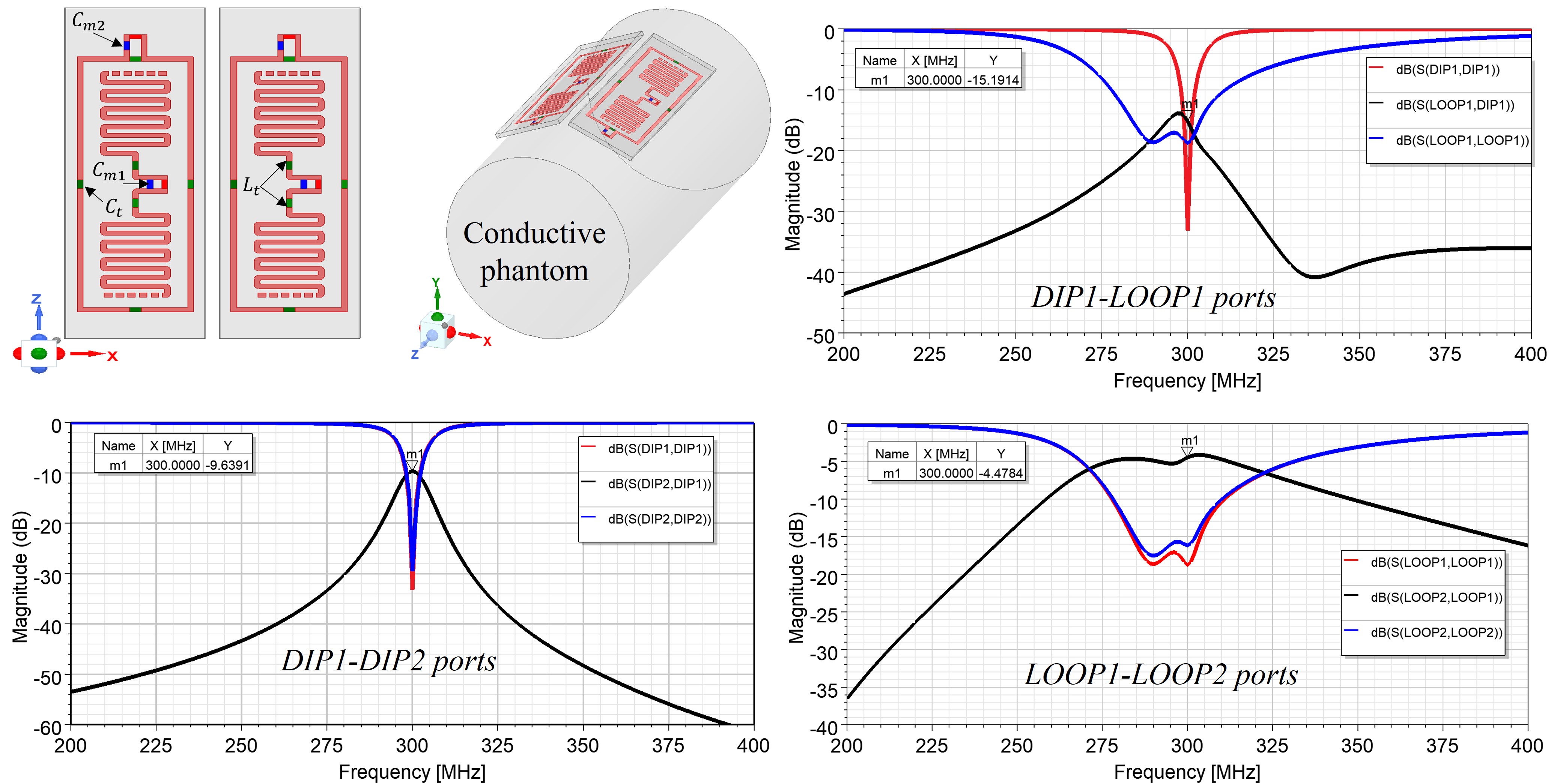
Fig. 1. Model of the pair of dipole-Loop design placed 5 mm on top the conductive phantom and tuned for 300 MHz (electrical parameters: Ct= 3.8 pF, Lt = 91.5 nH, Cm1 = 19.4 pF, Cm2= 9 pF). Simulated scattering parameters of the design revealing strong electromagnetic coupling between adjacent resonators.
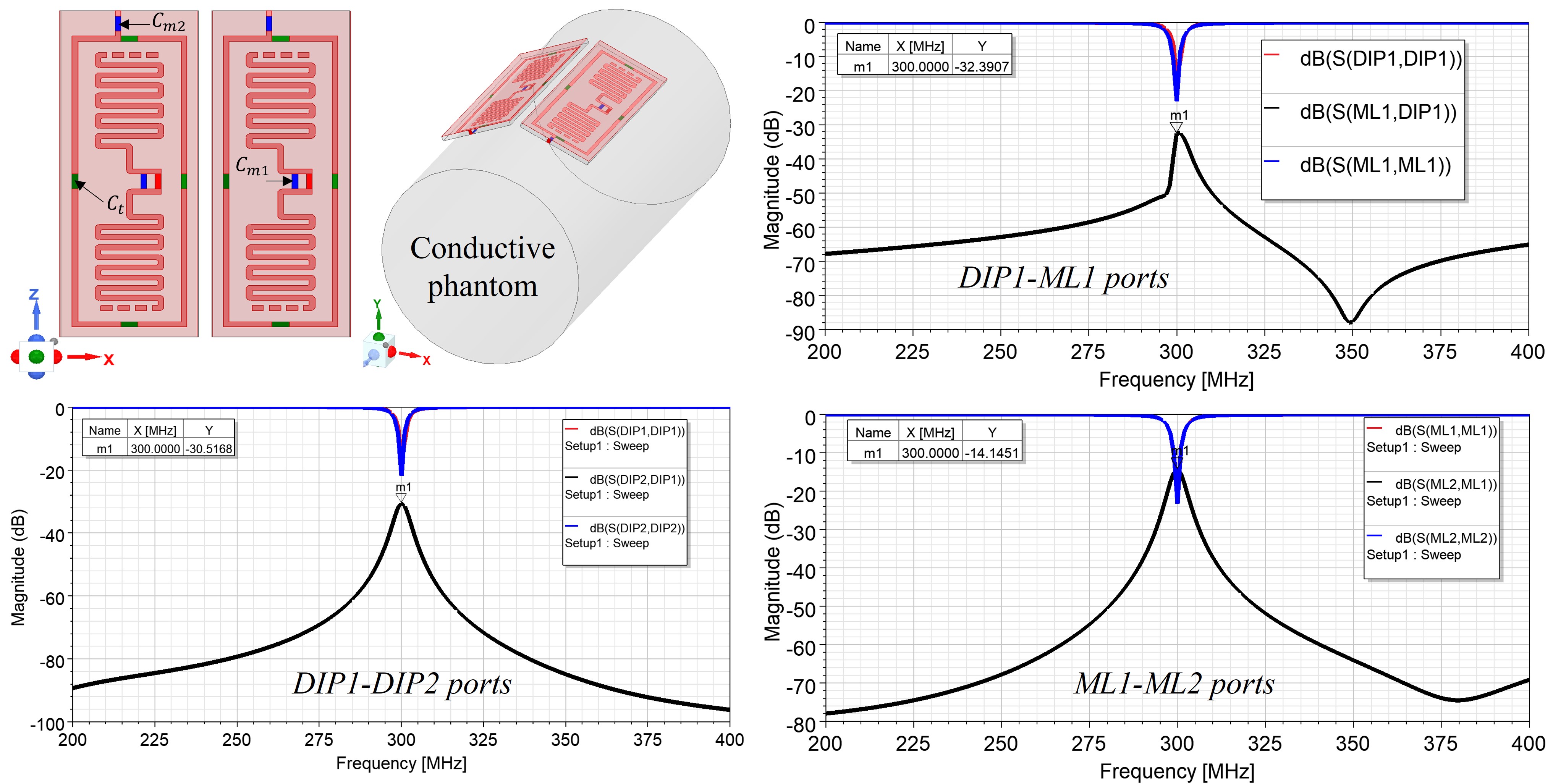
Fig. 2. Model of the pair of the shielded dipole and microstrip Loop design placed 5 mm on top the conductive phantom and tuned for 300 MHz (electrical parameters: Ct= 10 pF, Cm1 = 50 pF, Cm2= 6.5 pF). Simulated scattering parameters of the proposed design showing excellent decoupling between adjacent resonators
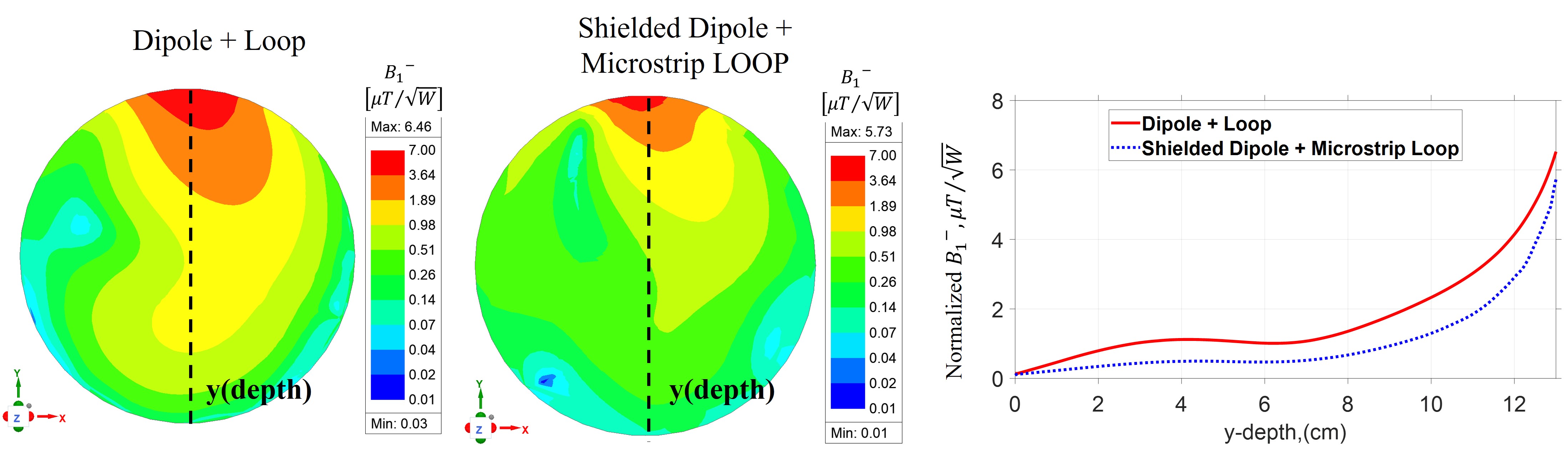
Fig. 3. Simulated receive B1 field distribution normalized to 1 W of input power in the transversal plane and its one-dimensional profile along the dash line for a single DL and shielded dipole-microstrip loop design, both driving in quadrature.
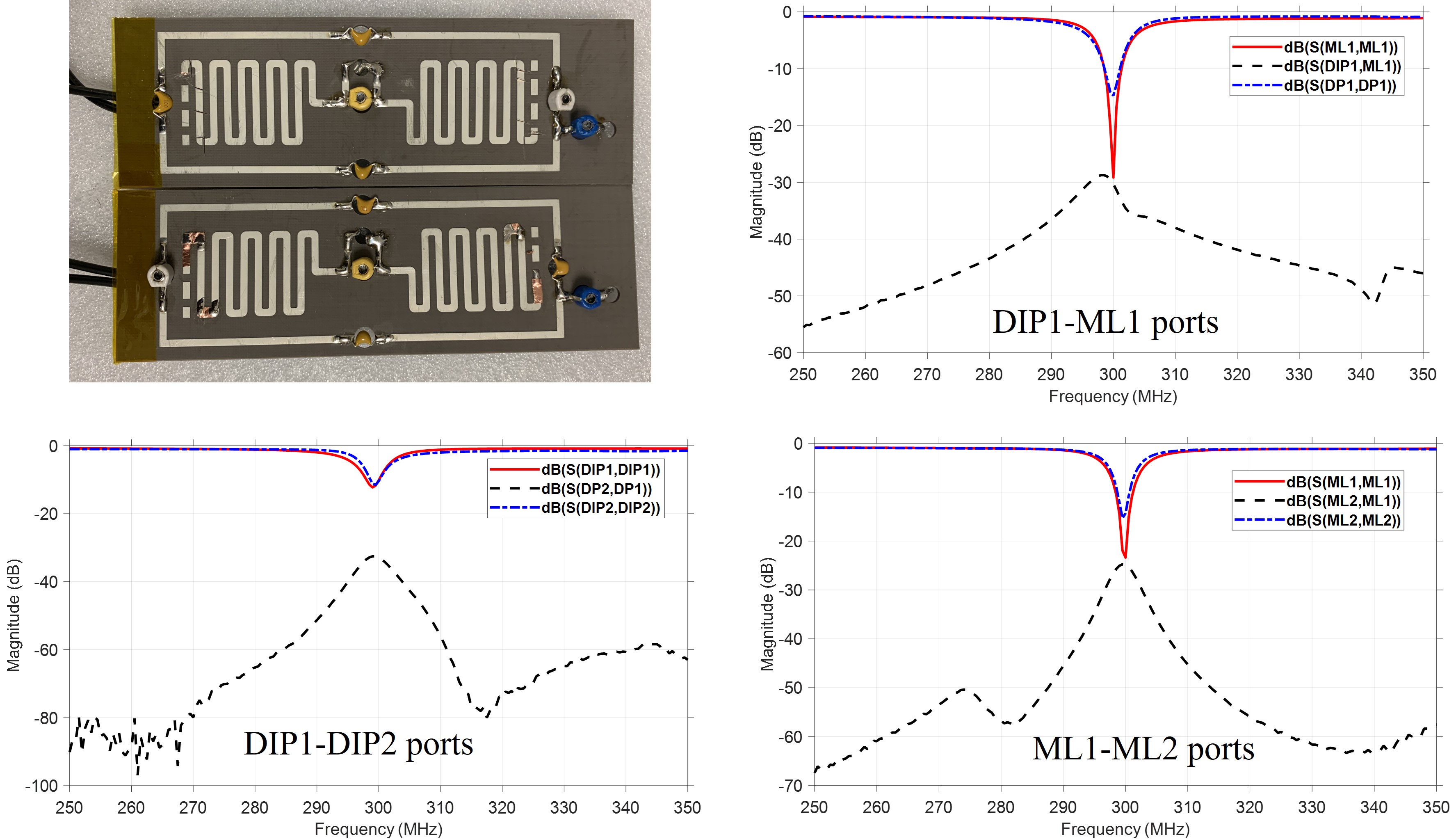
Fig. 4. Prototype of the pair of shielded dipole and microstrip loop resonators stacked very close to each other. Bench test results of the design showing excellent matching and good isolation between the dipoles (DIP1-DIP2) ports as well as the microstrip loop (ML1-ML2) ports at 300 MHz.
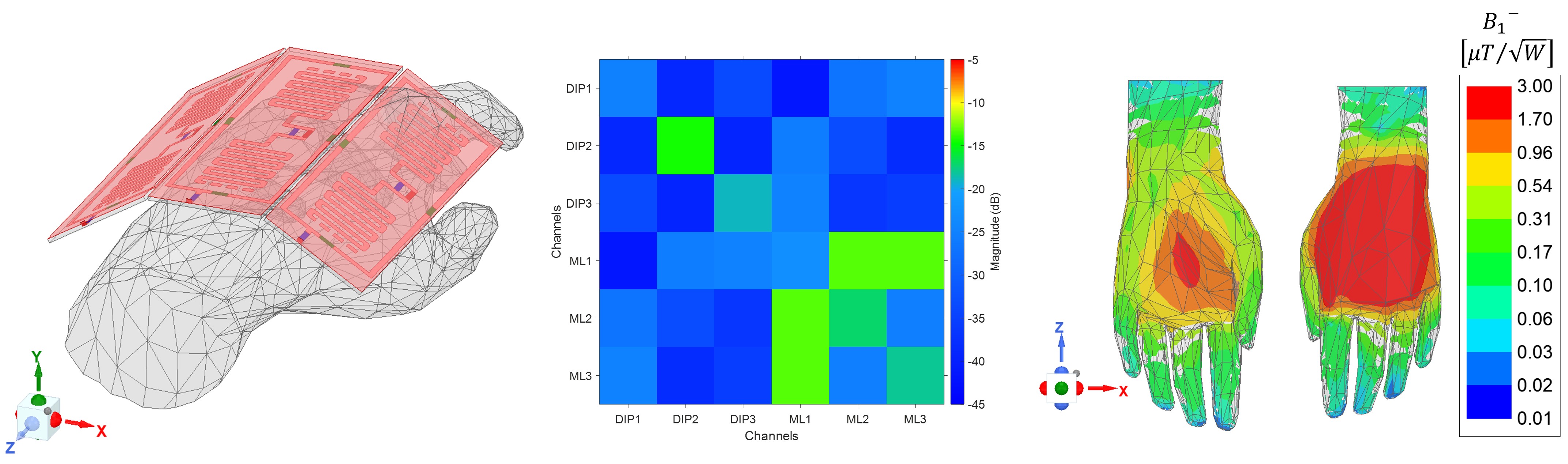
Fig. 5. Receive sensitivity B1 of the well-decoupled 3 channel shielded dipole-Loop quadrature array around a hand voxel phantom. Uniform field distribution is obtained in the coronal plane.