3899
The Metaslab: A combined Metamaterial and Metasurface for Improved Transmit Performance and Use as a Receive Array.1Electrical and Computer Engineering, University of Alberta, Edmonton, AB, Canada, 2Oncology, Medical Physics, University of Alberta, Edmonton, AB, Canada
Synopsis
Keywords: RF Arrays & Systems, Body, metamaterial
Abdominal and thoracic imaging at 3T suffers from inhomogeneous transmit fields and hot-spots in specific absorption rate (SAR) that limit image quality and imaging efficiency, respectively. We combine a lightweight metamaterial and metasurface (the ‘metaslab’) to enhance transmit efficiency and homogeneity, as well as to reduce SAR. The metaslab is further able to operate as a receive array with four distinct sensitivity patterns and sensitivity comparable to that of a conventional 4-element loop receive array. The metaslab is much lighter than comparable dielectric pads and achieves all these benefits in a similar package as a conventional coil array.Introduction
At 3T, the right-hand circularly polarized radio-frequency (RF) transmit field (Methods
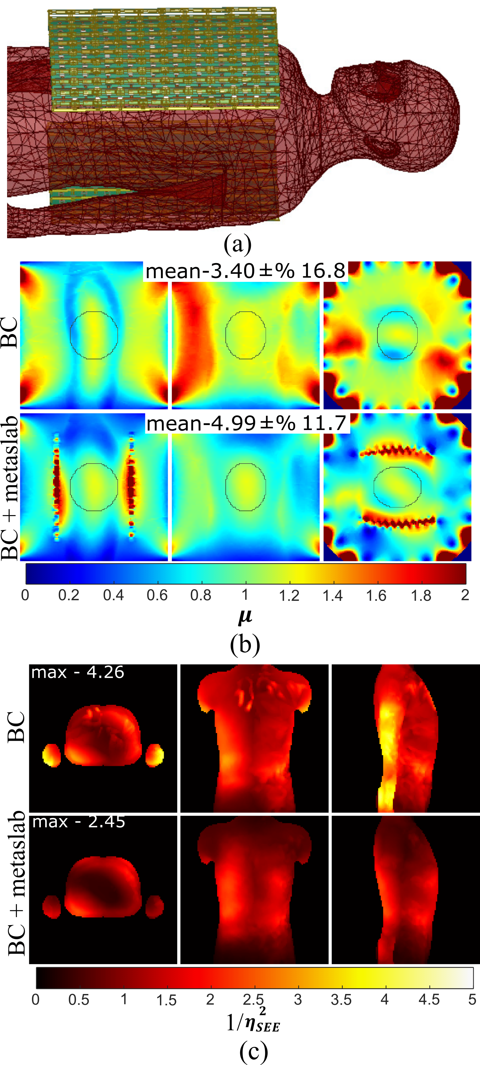
The MTM slab (Figure 1a) consists of eleven adjacent 1D strips of overlapping copper conductor (18μm thick) on thin ROGERS 3006TM substrate (0.25mm thick, εr=6.15, tanδ=0.002) connected to a second layer made of strips of copper and separated by polycarbonate spacers. Optimization and tuning was described previously1,2. The MTS is sandwiched between the MTM layers and consists of a 2D grid of overlapping parallel plate capacitors made from thin ROGERS 3003TM substrate (0.125mm thick, εr=3, tanδ=0.0007). The MTS is tuned similarly to Ref. (6) and has minimal interaction with the MTM. The materials cost of the metaslab was <$100 USD and weight <400g. The simulation rendering of the metaslab and four loop conventional surface coil receive array simulated/constructed for comparison of the receive performance are shown in Figure 1b. A hybrid birdcage coil model emulating the Philips Achieva 3T scanner system body coil is included (54cm length, 30cm coil radius with 32cm shield radius) as the transmitting structure. Two metaslabs were made and one was fitted with two receive ports placed at strategic locations on both the MTM and MTS (four ports total) (Figure 1c). The transmit fields with 1kW RMS accepted power split between quadrature ports of the birdcage coil were simulated (Ansys, HFSS). These were compared to flip angle (FA) maps acquired by varying the prescribed FA using a 2D multi-slice SPGR sequence (50°, 100° and 150°) and pixelwise least squares fitting according to the SPGR equation (500Hz/pixel, 70×70×33 matrix, 6×6×6mm3 resolution, TE=2.6ms, TR=800ms) in a rectangular phantom filled with 3.6g/L NaCl and 1.96g/L CuSO4⋅5H2O aqueous solution. To quantify the impact on SAR, the fields were also simulated with the standard HFSS 2022 male human body model. The simulated fields were used to calculate the intrinsic SNR (receive sensitivity) in the phantom (normalized as the signal that would be received with 90° FA and TR>>T1), with the fields produced by the elements of the array combined as in reference7.Results and Discussion
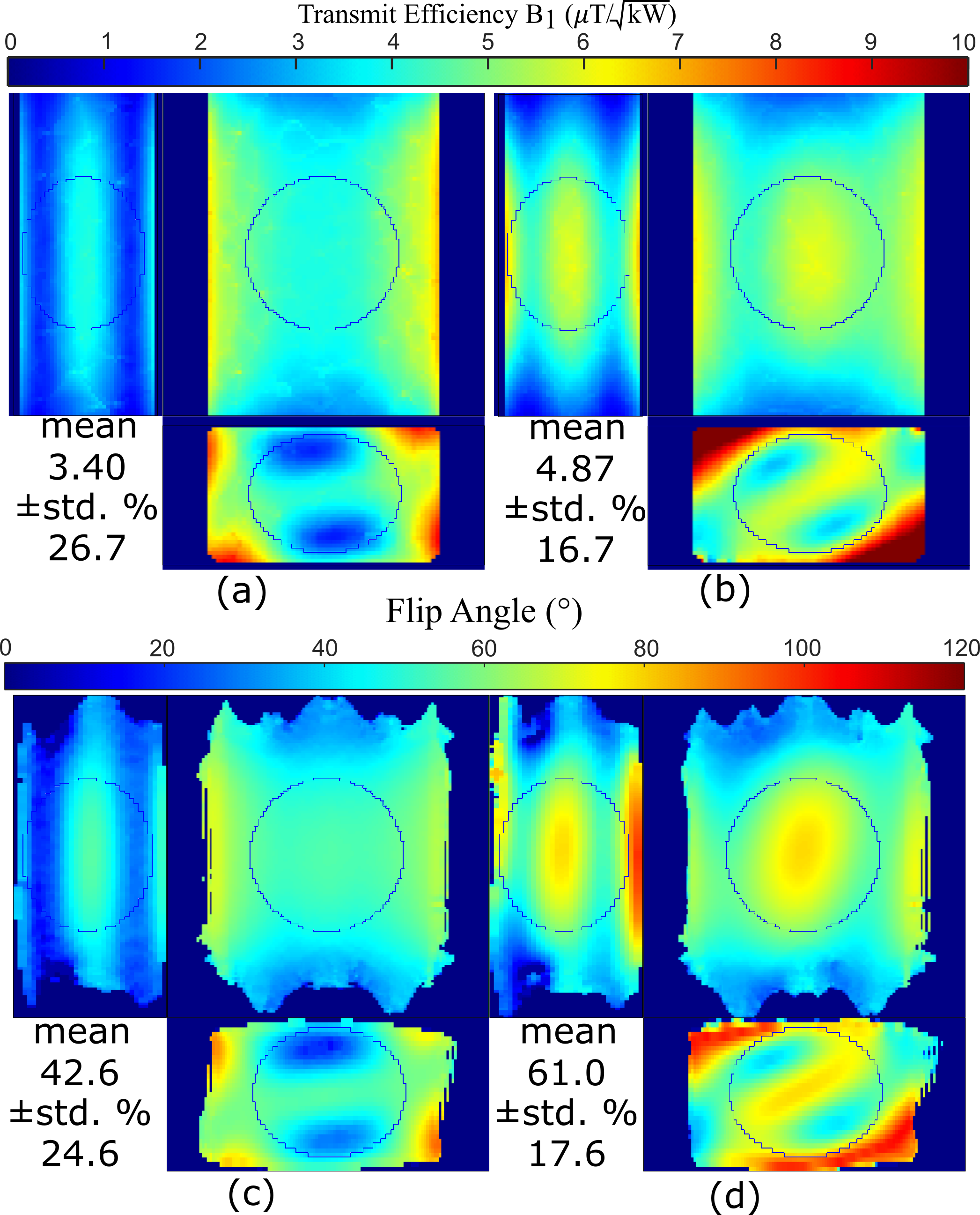
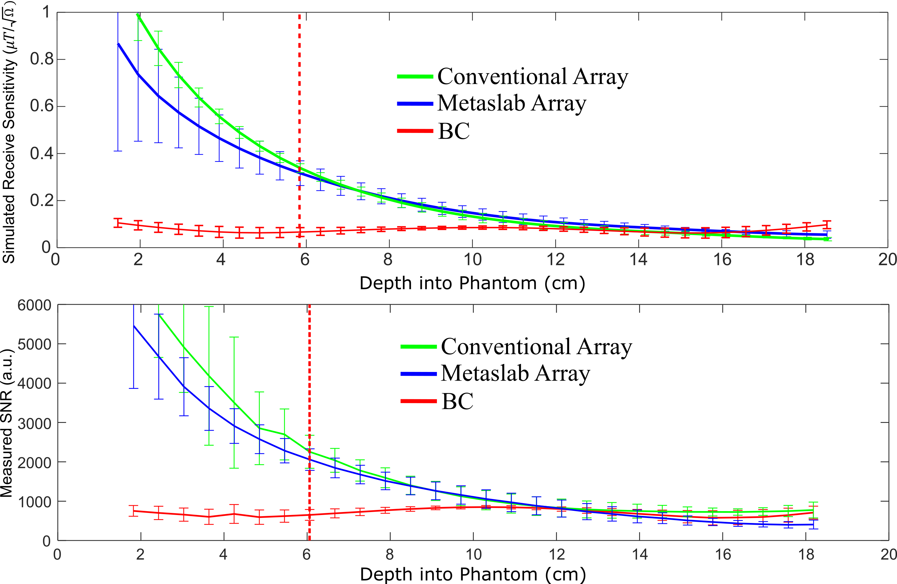
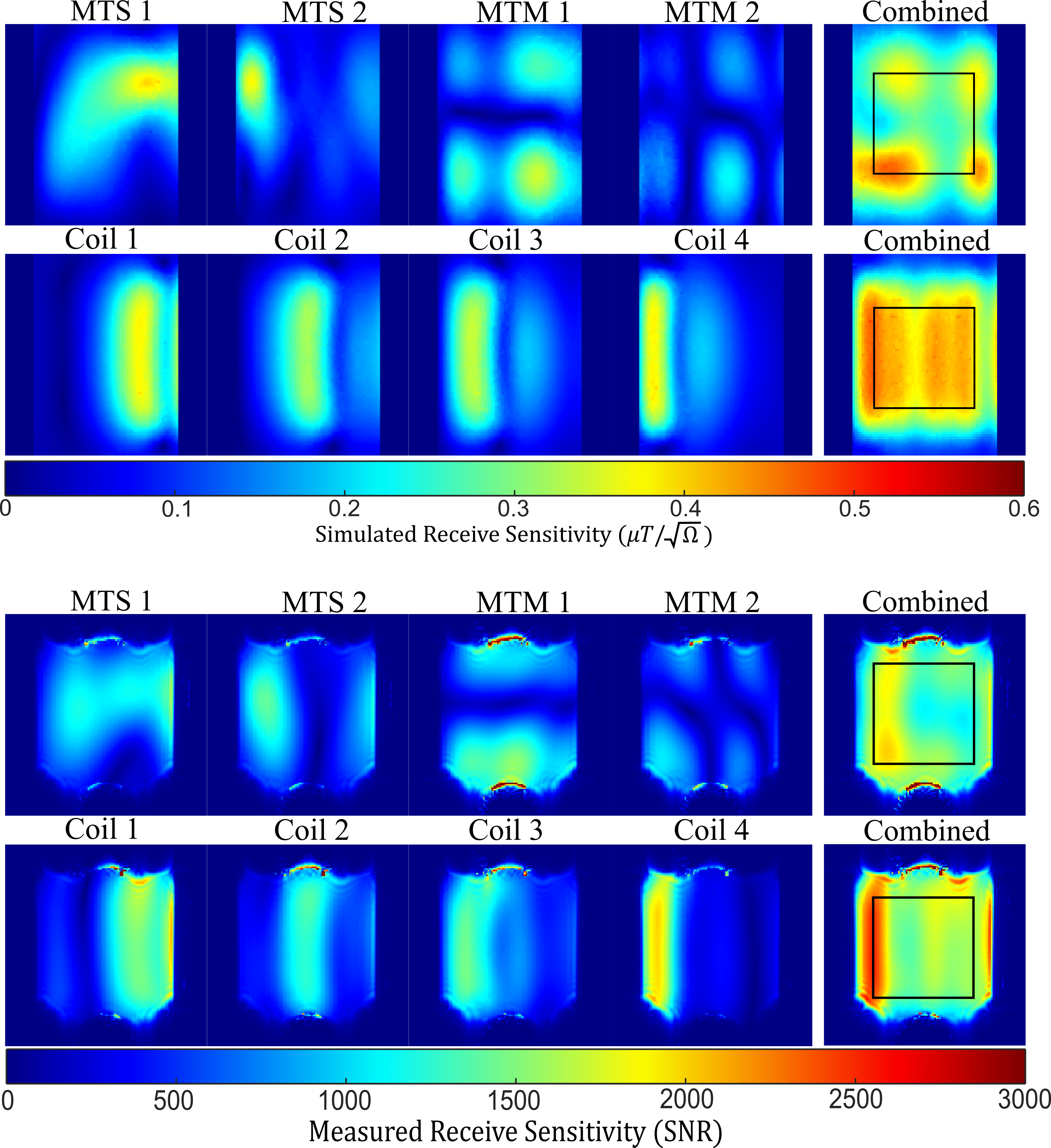
The simulated and measured transmission efficiency maps in three orthogonal slices are shown in Figure 2 with only the BC (a, c), or also with two metaslabs (b, d). A 43% increase in transmit efficiency is found within an ellipsoidal region of interest (8.5cm×10cm×10cm radii) in both simulation and measurement, with an improved coefficient of variation of the field (17% in simulation vs. 18% in measurement), compared to the BC alone (27% in simulation vs. 25% in measurement). The mean transmit field produced relative to the peak 10g averaged local SAR is termed the safety excitation efficiency (ηSEE). Within the human body model (Figure 3a) the transmit efficiency increases by 47% while 1/ηSEE2 (the maximum local SAR for a given flip angle) is reduced by 43% (Figure 3b). The simulated receive sensitivity and measured receive sensitivity (adjusted pixelwise for FA) within an 8.5cm×10cm central region of interest along the depth of the phantom is shown in Figure 4. Beyond a depth of approximately 6-8 cm, where coil losses have the greatest impact on SNR, the metaslab and conventional array have approximately the same receive performance. At shallower depths the SNR remains high even though the receive sensitivity of the metaslab is somewhat lower than that of the conventional array. Additional receive elements (coils placed under the MTM slab) could be included to enhance the receive performance2 if designed to couple minimally with the metaslab. The sensitivity patterns in a coronal slice at ~6 cm below the receive elements are shown in Figure 5, with the optimally combined receive sensitivity of both the coil array and metaslab included. In contrast to the elements of the coil array, the individual receiving ports of the metaslab have less localized sensitivity profiles but are nevertheless spatially distinct from each other (i.e., mathematically orthogonal).Conclusion
The hybrid MTM-MTS metaslab improves transmit efficiency and homogeneity in both simulation and measurement, while reducing the maximum local 10g SAR. It is also used as a receive array which provides the benefits of high receive sensitivity in a large FOV without an additional coil array or heavy dielectric pads.Acknowledgements
This work was supported by the Alberta Innovates postdoctoral fellowship in health innovation, the Office of the Provost and VP of the University of Alberta, and the Natural Sciences and Engineering Research Council (NSERC) of Canada Discovery Grants program. We thank CMC Microsystems for software access and support by the University of Alberta Faculty of Engineering IT. We thank Philips Healthcare for technical support, and Dr. R. Luechinger for the PATI software used to transfer data.References
1.Rémillard L, Maunder A, Iyer AK, De Zanche N. Transmit Performance of a Metamaterial Slab as a Passive RF Shimming Element for 3T MRI. 0195, Proceedings of the 31st Annual Meeting of ISMRM 2022.
2.Rémillard L, Maunder A, Iyer AK, De Zanche N. Hybrid 3T 8-channel Receive Array Using a Metamaterial Slab and Companion Loop Elements: Comparison to a Conventional Array. Proceedings of the 31st Annual Meeting of ISMRM, 2185, 2022.
3.Slobozhanyuk AP, Poddubny AN, Raaijmakers AJE, et al. Enhancement of Magnetic Resonance Imaging with Metasurfaces. Adv Mater. 2016;28(9):1832-1838. doi:10.1002/adma.201504270
4.Stoja E, Konstandin S, Philipp D, et al. Improving Magnetic Resonance Imaging with Smart and Thin Metasurfaces. Sci Rep. 2021;11(1):16179. doi:10.1038/s41598-021-95420-w
5.Schmidt R, Slobozhanyuk A, Belov P, Webb A. Flexible and compact hybrid metasurfaces for enhanced ultra high field in vivo magnetic resonance imaging. Scientific Reports. 2017;7(1):1678. doi:10.1038/s41598-017-01932-9
6.Vorobyev V, Shchelokova A, Efimtcev A, et al. Improving homogeneity in abdominal imaging at 3 T with light, flexible, and compact metasurface. Magnetic Resonance in Medicine. 2022;87(1):496-508. doi:10.1002/mrm.28946
7.Maunder A, Rao M, Robb F, Wild JM. An 8-element Tx/Rx array utilizing MEMS detuning combined with 6 Rx loops for 19F and 1H lung imaging at 1.5T. Magnetic Resonance in Medicine. n/a(n/a). doi:10.1002/mrm.28260
Figures
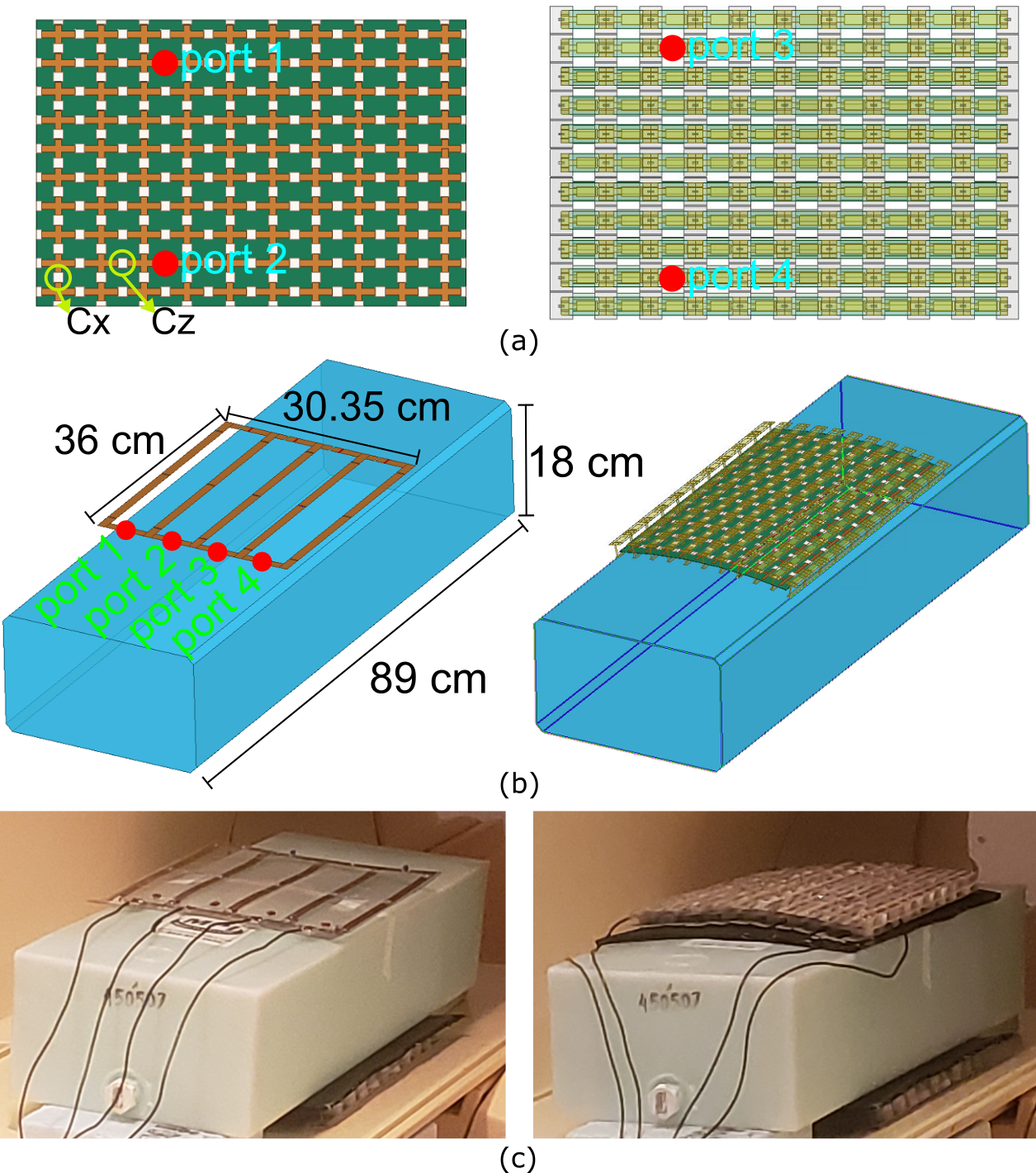
Figure 1: (a) Top-view of MTS and MTM slab with locations of ports. (b) Rendering of the simulation model for the 4-element conventional array and metaslab on torso sized phantom. (c) The measurement setup for transmit performance of metaslabs and receive performance of metaslab and coil array. Note second metaslab under the phantom.