3898
Improving signal-to-noise ratio and contrast in Wrist Magnetic Resonance Imaging at 1.5T with Wireless Metasurface Resonantor1Department of Radiology, Beijing Tsinghua Changgung Hospital, School of Medicine, Tsinghua University, Beijing, China, 2State Key Laboratory of Tribology, Department of Mechanical Engineering, Tsinghua University, Beijing, China, 3Center for Biomedical Imaging Research, Department of Biomedical Engineering,School of Medicine, Tsinghua University, Beijing, China, 4State Key Laboratory of New Ceramics and Fine Processing, School of Materials Science and Engineering, Tsinghua University, Beijing, China
Synopsis
Keywords: Non-Array RF Coils, Antennas & Waveguides, Joints, Metasurface
We designed a wireless metasurface resonator(WMR) for wrist magnetic resonance imaging(MRI) at 1.5T and tested the imaging effect. Phantoms and 14 wrist jionts(7 healthy volunteers) were examed with T1W SE and fat-suppressed PDW FSE sequences at a 1.5T MRI system. Commercial 12-channel wrist array coil(12CH-WR) and WMR(coupling with integrated spine coil) were used to receive MR signal respectively. We found that WMR could improve the image SNR by 1.5~2 times, and significantly improve the image contrast compared with the traditional 12CH-WR.Introduction
Wrist is composed of numerous small anatomical structures, which makes the wrist magnetic resonance imaging(MRI) challenging. It is necessary to obtain high spatial resolution, signal-to-noise ratio(SNR) and contrast resolution of wrist MR images for wrist disease evaluation1-3. Recently, metasurface resonators have been proved to improve the local SNR of MRI4-9. However most of previous studies had defects such as poor image uniformity and uncontrollable RF transmit fields(B1+), besides few studies expounded the change of image contrast. In our study, a novel wireless metasurface resonator(WMR) is designed and evaluated on wrist MRI at 1.5T including both image SNR and contrast.Methods
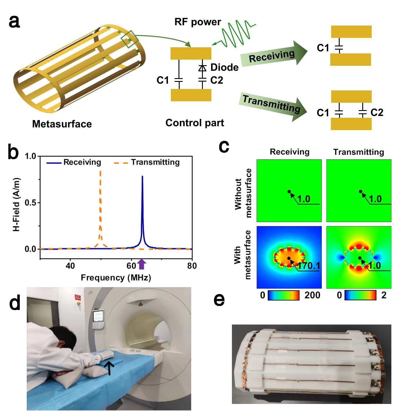
Construction of WMR: The WMR consists of twelve wires and control part, on which capacitors and diodes are soldered (Fig. 1a).The physical drawing and setup method of WMR were shown in Fig1d and 1e. Frequency response and field distributions of WMR was simulated with CST.MR examination and image evaluation: Specially designed phantoms(composed of five subcomponents with different electromagnetic parameters, S1-S5) and 14 wrist jionts(7 healthy volunteers) were scanned at a 1.5T MRI system uMR 570(United Imaging, Shanghai, China). MRI sequences included T1-weighted spin echo(T1W SE) and fat-suppressed proton density-weighted fast spin echo(FS PDW FSE). Two different signal receiving methods, commercial 12-channel wrist array coil(12CH-WR) and WMR coupling with integrated spine coil(WRM-SP), were used to acquire images.All images were quantificationally analyzed by an experienced radiologist, which included image SNR and CNR.
Statistical analysis: Firstly, Shapiro-Wilk test had been used to demonstrate that all quantitative data came from normal distribution. Then, paired student t test was performed to compared SNR and CNR between two acquisition methods.Signifificance was set at P < 0.05.
Results
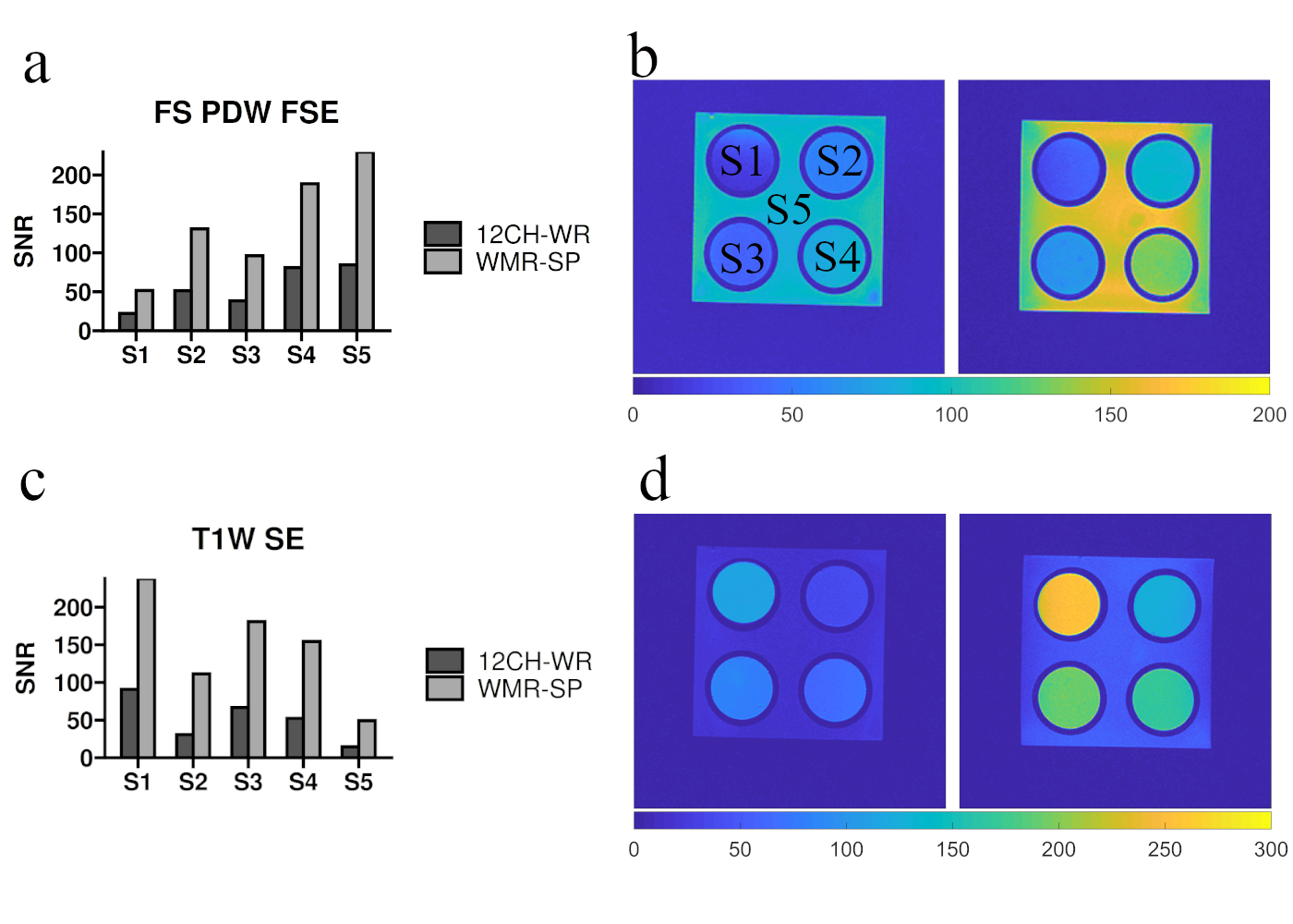
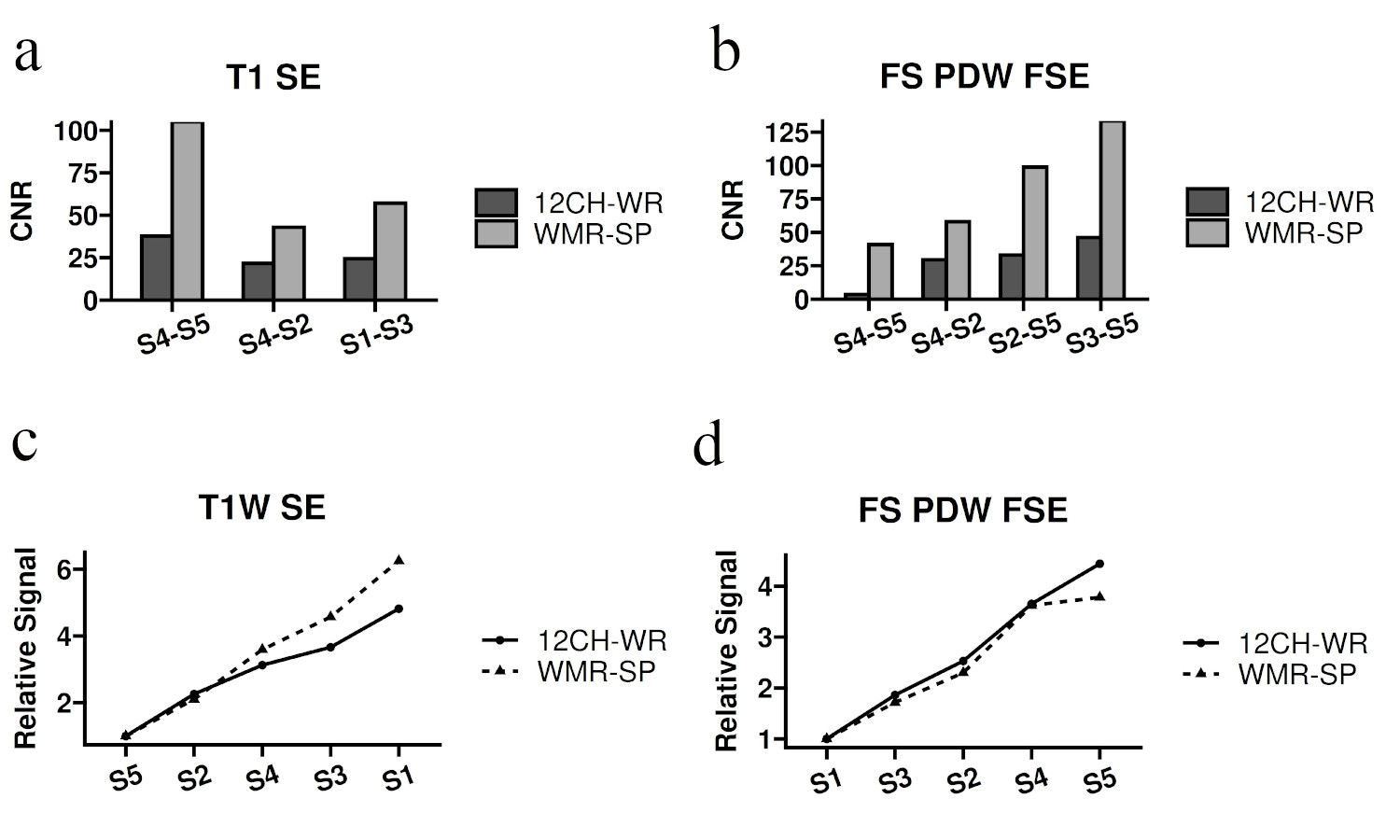
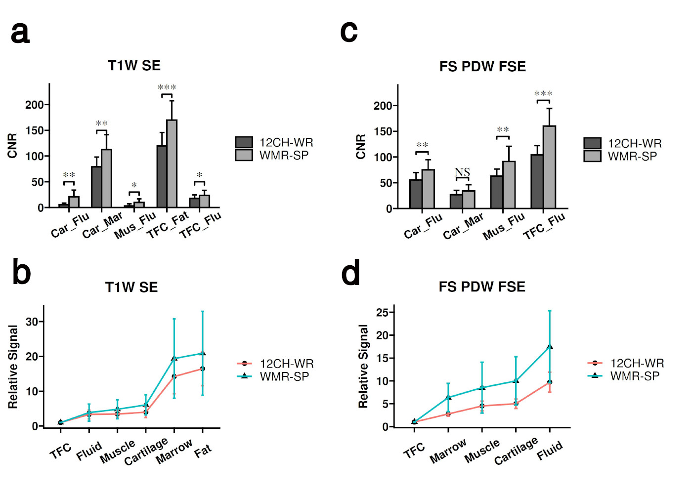
Electromagnetic simulation: By sensing the variation of the RF power, the metasurface possesses different resonant frequencies in transmitting and receiving periods(Fig. 1b). In receiving period, the metasurface resonates at the Larmor frequency and significantly enhances the magnetic field (170.1 times) (Fig. 1c). While in transmitting period, the resonant frequency of the metasurface is much lower than the Larmor frequency, thus the metasurface no longer enhances the magnetic field. To sum up, the metasurface greatly enhances the receiving field and keeps the transmitting field unchanged at the same time.In phantom study: Image SNRs of each component of the phantom acquired by WMR-SP were significantly higher than that acquired by 12CH-WR(~ 1.5-2 times) both in FS PDW FSE(Fig.2a,b) and T1W SE(Fig.2c,d). In addition, compared with 12CH-WR, WMR-SP significantly improved the CNRs between the components of the phantom image(Fig.3a,b). The change trend of relative signals of different components in the image acquired by WMR-SP is consistent with that acquired by 12CH-WR(Fig.3c,d).
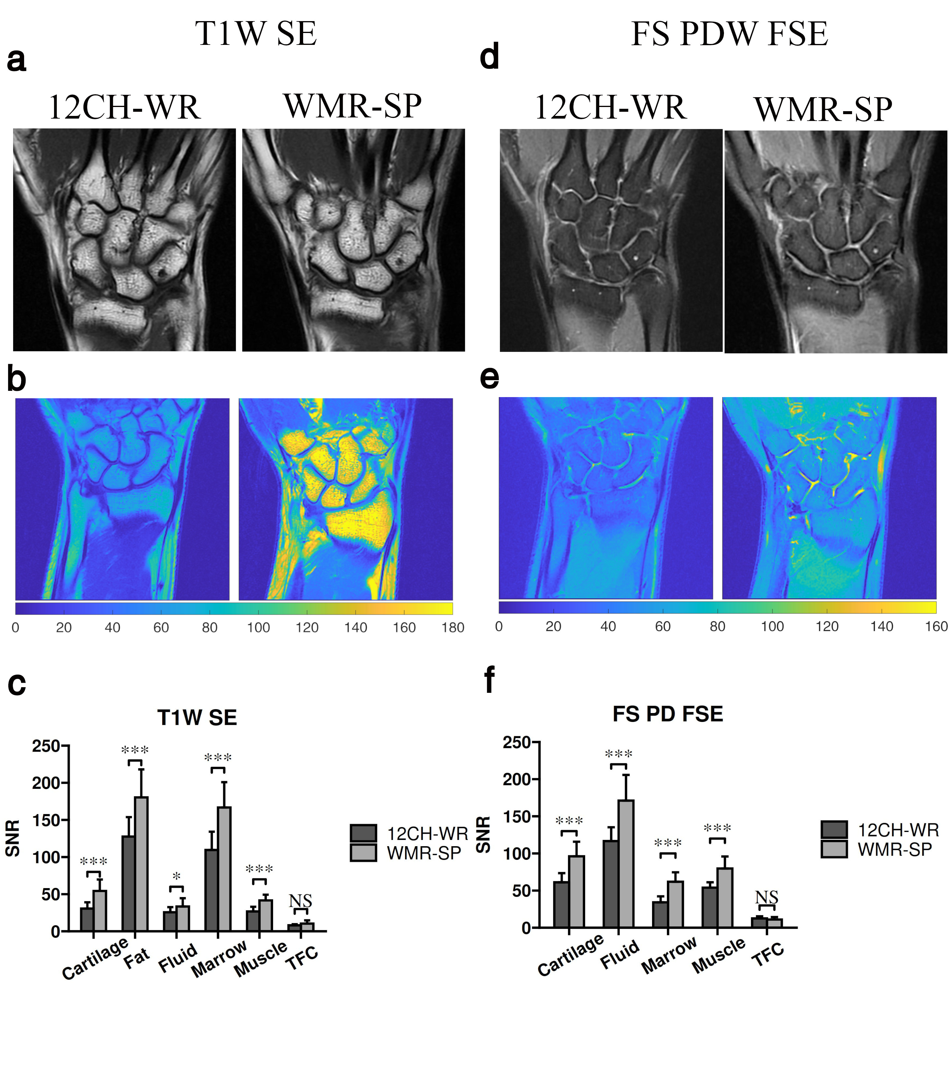
In vivo study: The SNRs of cartilage, fat, fluid, marrow and muscle on T1W SE images aqcuired by WMR-SP were significantly higher than that acquired by 12CH-WR(P<0.05)(Fig.4a~c). And the SNRs of cartilage, fluid, marrow and muscle on FS PDW FSE images aqcuired by WMR-SP were significantly higher than that acquired by 12CH-WR(P<0.05)(Fig.4d~f). Images acquired by WMR-SP had higher CNRs between different tissues(Fig.5a,b) and similar signal change trend(Fig.5c,d).
Discussion
In this study, we designed a novel WMR, and proved that it can not only significantly improve the SNR of MRI, but also increase the contrast between different tissues both in phantom and vivo, compared with 12-channel wrist phase array coil.Compared with the traditional multi-channel phased array receiving coil, the WMR has a lot of advantages. First, WMR does not require installation and cable connection by using it with the MRI integrated coil. Second, WMR is smaller and lighter than multi-channel array coil. Third, WMR can obtain higher quality MR images.
In comparison to most previous metasurface devices used for MRI, the novel WMR can obtain more uniform MR images. In addition, the specially designed intelligent switch can selectively enhance the RF receiving field without affecting the RF transmitting field. In addition to focusing on the impact of WMR on image SNR, we also proved that WMR can significantly improve image contrast, which was rarely involved in previous studies. The improvement of image contrast is more conducive to the detection of lesions.
Conclusion
The WMR we designed can selectively enhance the RF receiving field, which can significantly improve the SNR and contrast of the image. Therefore, we believe that introducing wireless metamaterial resonator into MRI is an effective and novel method to improve image quality.Acknowledgements
No acknowledgement found.References
1. Chang A L, Yu H J, von Borstel D, et al. Advanced Imaging Techniques of the Wrist[J]. AJR. American journal of roentgenology, 2017,209(3):497-510.
2. Tiegs-Heiden C A, Howe B M. Imaging of the Hand and Wrist[J]. Clinics in Sports Medicine, 2020,39(2):223-245.
3. Vassa R, Garg A, Omar I M. Magnetic resonance imaging of the wrist and hand[J]. Pol J Radiol, 2020,85:e461-e488.
4. Slobozhanyuk A P, Poddubny A N, Raaijmakers A J, et al. Enhancement of Magnetic Resonance Imaging with Metasurfaces[J]. Adv Mater, 2016,28(9):1832-1838.
5. Stoja E, Konstandin S, Philipp D, et al. Improving magnetic resonance imaging with smart and thin metasurfaces[J]. Sci Rep, 2021,11(1):16179.
6. Puchnin V, Solomakha G, Nikulin A, et al. Metamaterial inspired wireless coil for clinical breast imaging[J]. J Magn Reson, 2021,322:106877.
7. Lopez M A, Freire M J, Algarin J M, et al. Nonlinear split-ring metamaterial slabs for magnetic resonance imaging[J]. Applied Physics Letters, 2011,98(13):133508.
8. Algarin J M, Lopez M A, Freire M J, et al. Signal-to-noise ratio evaluation in resonant ring metamaterial lenses for MRI applications[J]. New Journal of Physics, 2011,13(11):115006
9. Zubkov M, Hurshkainen A A, Brui E A, et al. Small-animal, whole-body imaging with metamaterial-inspired RF coil[J]. NMR Biomed, 2018,31(8):e3952.
Figures