3747
Rat angiography from far away: design and performance of a small bath cryostat with NMR capability for transport of hyperpolarized samples.1IPHYS, EPFL, Lausanne, Switzerland, 2Health Tech, Technical University of Denamrk, Kgs. Lyngby, Denmark, 3Health Tech, Technical University of Denmark, Kgs. Lyngby, Denmark, 4Aarhus University Hospital, Aarhus, Denmark
Synopsis
Keywords: New Devices, Hyperpolarized MR (Non-Gas), transportable hyperpolarization
Hyperpolarization via dissolution Dynamic Nuclear Polarization has the potential to revolutionize diagnostic radiology. Nevertheless, the methodology struggles to enter everyday clinical practice. One of the reasons why broad consensus among clinicians is still missing lies in the technical complexity that characterize hyperpolarization via dDNP. Differently from PET, hyperpolarized MR contrast agent cannot be transported and have to be prepared on-site. We developed a robust methodology to change this paradigm. We herein present our latest updates on transportable hyperpolarization technology.Introduction
As of today, dissolution Dynamic Nuclear Polarization (dDNP)1 is the only clinically available hyperpolarization technique for 13C-MRI. Despite the clear path towards personalized medicine that dDNP is paving as an alternative and/or complement to Positron Emission Tomography (PET),2-3 the technique struggles to enter everyday clinical practice. Because of the minute-long hyperpolarization lifetime after dissolution, one of the reasons lies in the need and consequent complexities of having the machine that generates the hyperpolarization (i.e. the dDNP polarizer) on site. Since some years, research groups are working to make hyperpolarization transportable. Two different methods have been developed that allow “freezing” of the nuclear spin state prior to samples extraction as a frozen solid from the polarizer.4-5Nevertheless, so far, all attempts of transport have been limited to a very small scale and to the level of proof-of-principle experiments.6 The main reason for that is the lack of adequate hardware, strategy, and control on most of the crucial parameters. To bridge the technical gap with PET and provide MRI facilities with hours long relaxing hyperpolarized compounds at controlled conditions, a new generation of low cost/small footprint liquid He cryostats equipped with a magnetically enforced cryogenic probe is needed. In this study, we detail the theoretical and practical construction of a hyperpolarized samples transportation device small enough to fit in a car, able to hold a sample at 4.2 K for almost 8 h, and equipped with a purpose-built probe that provides enough magnetic field upon insertion of the sample and NMR quality homogeneity at storage position. We tested the device over a 4 h long transport to provide an MRI clinical scanner with hyperpolarized [1-13C]HPO01 for rat angiography.
Materials and Methods
Design of the magnetically-enforced probeIn Figure1 we report 3D-drawings of the magnetically-enforced cryogenic probe. The latter was build around a small-foot-print 1T Halbach magnet for storage of the hyperpolarized samples and equipped with a magnetic rail to shelter spin order upon insertion.
Thermodynamic model for cryostat optimization
Inspired by the paper from Caplin et al.,7 we developed a thermodynamic model to asses the feasibility and optimize liquid He consumption of the compact transportation device. Referring to the sketch reported in Figure2, equation [1] can be be solved in three steps, from Z0 to Z1, from Z1 to Z2 from Z2 to Z3, to determine the best temperature profile as a function of the length of the cryostat neck and position of the radiation shields:
$$\frac{dT}{dz}=\frac{\mu c_pT-{\sigma_{SB}rad}_{n+1\rightarrow n}\left(T_{n+1}^4-T_n^4\right)}{{CS}_{steel}k_{steel}\left(T\right)+{CS}_{He}k_{He}\left(T\right)}; [1]$$
Characterization of the storage magnet
The field value to find the correct 13C resonance was characterized as a function of the temperature using a Hall probe and 1H NMR on a sample of water:glycerol doped with 50 mM TEMPO.
Long-relaxing HP sample preparation
We followed a protocol based on non-persistent UV-radicals previously descibed.6 This time instead of [U-13C, d7]glucose we used HPO01 as substrate of interest. After sample extraction from the polarizer (6.7 T, 1.2 K) 13C relaxation was monitored via NMR from the transport device. Dissolution of the sample was performed after 4h from extraction using 6 mL of saline solution heated to 180°C.
MRI sequence and imaging protocol
The 13C dynamic angiogram was recorded injecting 1.5 mL of the HP solution (130 mM HPO01 concentration) into a rat prepared inside a 3T GE clinical scanner equipped with a full body 1H/13C rat coil. A 2D gradient echo spiral sequence was designed (FOV: 120mm x 120mm; matrix size: 120 x 120; TR: 44 ms; TE: 1 ms; readout: 21 ms; flip-angle: 5°) to record the dynamic of the HP compound within a single slice coronal view projection over 20 s with interframe delay of 0.5 s.
Results and Discussion
In Figure 3, for a fixed height of the IVC of 400 mm we report, as a function of the neck length, the liquid He consumption (A), the capacity of the He pot (B), the holding time (B). A neck length of 270 mm was the best solution to guarantee a a holding time of at least 8 h. By optimizing the position of the radiation shield, He consumption could be reduced to 0.273 L/h, with the larger contribution coming from heat conduction through the probe (10.5 W out of 13 W of total heat input). Building the cryostat following these indications we measured a He consumption of 0.285+/-0.004 L/h, in good agreement with simulations. In Figure4 we show the simulation (A,B) of the storage magnet field and its behavior as a function of temperature (C,D). As a consequence the 13C resonance at 4.2 K appeared at 10.56 MHz. After the quench the relaxation time of radical-free hyperpolarized sample was measured to be approx. 8h with a 13C polarization after dissolution of 20+/-2 %. In Figure 5 we report the rat angiogram. The signal was high enough to acquire 40 full-body coronal images over 20 s.Conclusions and Perspectives
Should transportable hyperpolarization via DNP become a reality, we herein provide important details to make it possible. We demonstrated feasibility and optimization of a compact liquid He transportation device with NMR capability. We tested it for the transport of a hyperpolarized substrate for angiographic purposes.Acknowledgements
This work was supported by the Swiss National Science Foundation SPARK grant (CRSK-2_190547), the Swiss National Science Foundation Ambizione grant (PZ00P2_193276), the ERC Synergy grant HyperQ (ID: 856432).References
[1] Ardenkjaer-Larsen, J. H. et al. Increase in signal-to-noise ratio of > 10,000 times in liquid-state NMR. Proc. Natl. Acad. Sci. U. S. A. 100, 10158–10163.
[2] Nelson, S. J. et al. Metabolic Imaging of Patients with Prostate Cancer Using Hyperpolarized [1-13C]Pyruvate. Sci. Transl. Med. 5, 198ra108 1–10.
[3] Kurhanewicz, J. et al. Hyperpolarized (13)C MRI: Path to Clinical Translation in Oncology. Neoplasia 21, 1–16 (2019).
[4] Capozzi, A., Cheng, T., Boero, G., Roussel, C. & Comment, A. Thermal annihilation of photo-induced radicals following dynamic nuclear polarization to produce transportable frozen hyperpolarized 13C-substrates. Nat. Commun. 8, 15757 (2017).
[5] Ji, X. et al. Transportable hyperpolarized metabolites. Nat. Commun. 8, (2017).
[6] Capozzi, A. et al. Metabolic contrast agents produced from transported solid 13C-glucose hyperpolarized via dynamic nuclear polarization. Commun. Chem. 4, 95 (2021).
[7] Caplin, A. D. & Cayless, A. T. Simple numerical modelling technique for cryostat design. Cryogenics 26, 678–681 (1986).
Figures
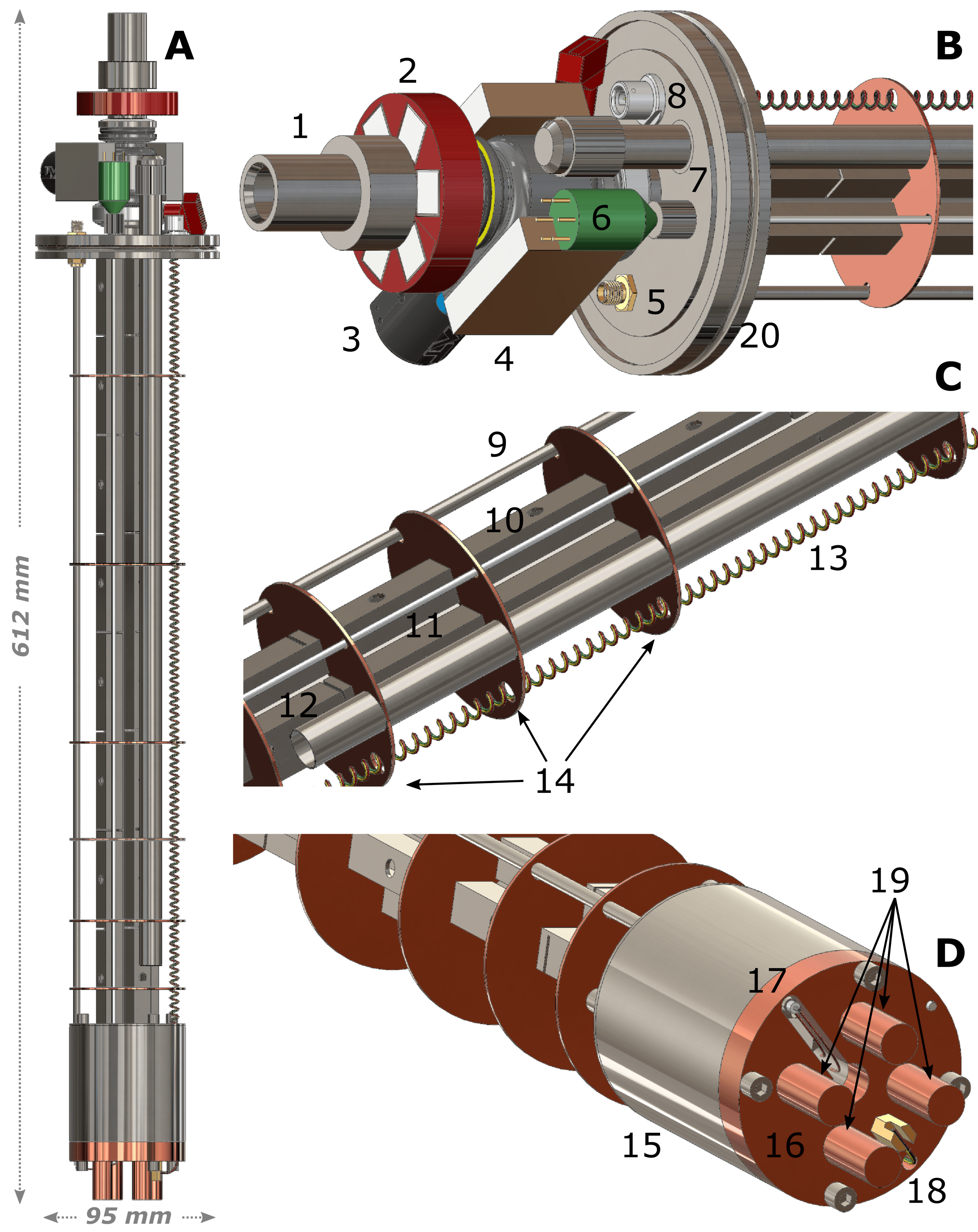
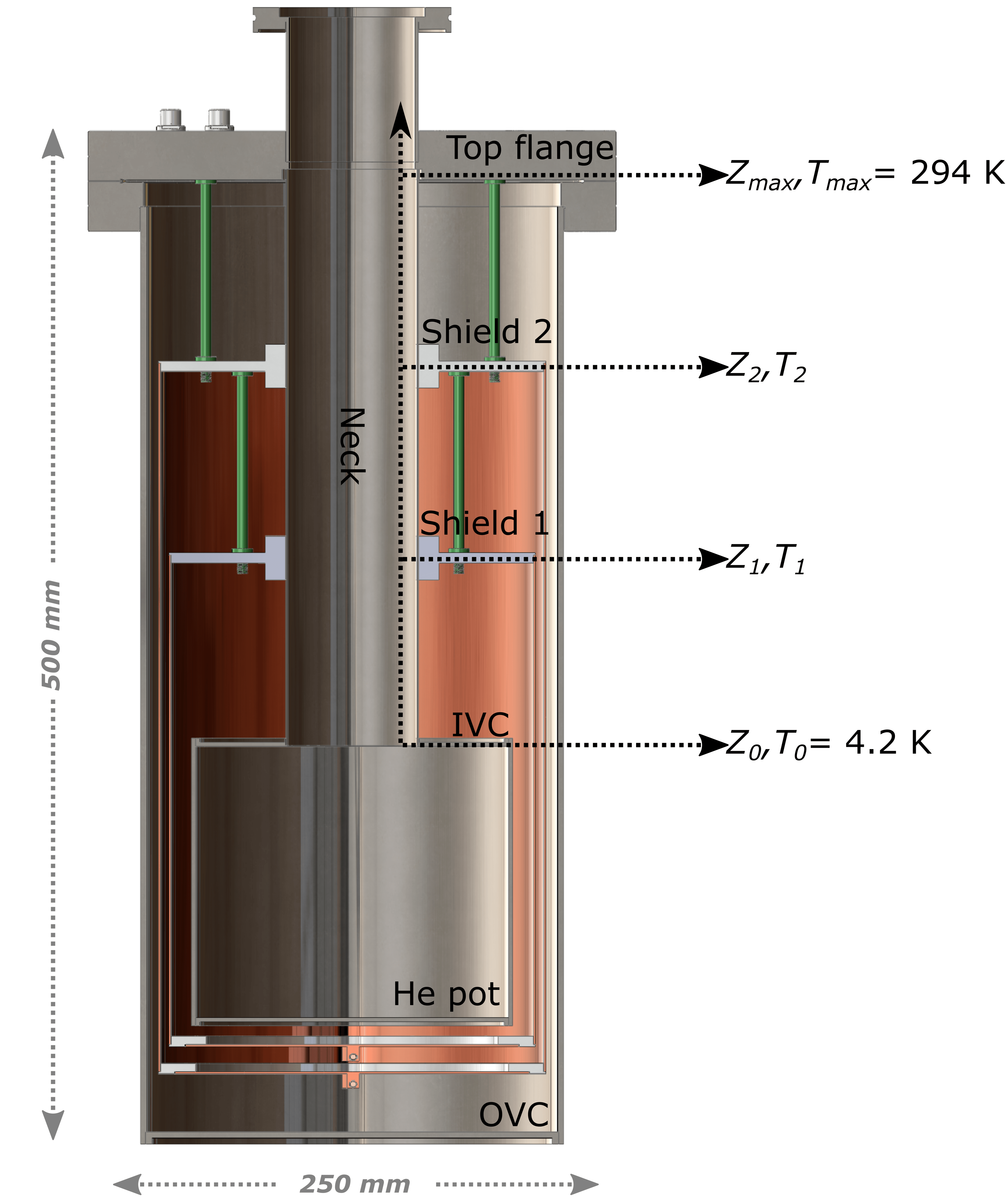
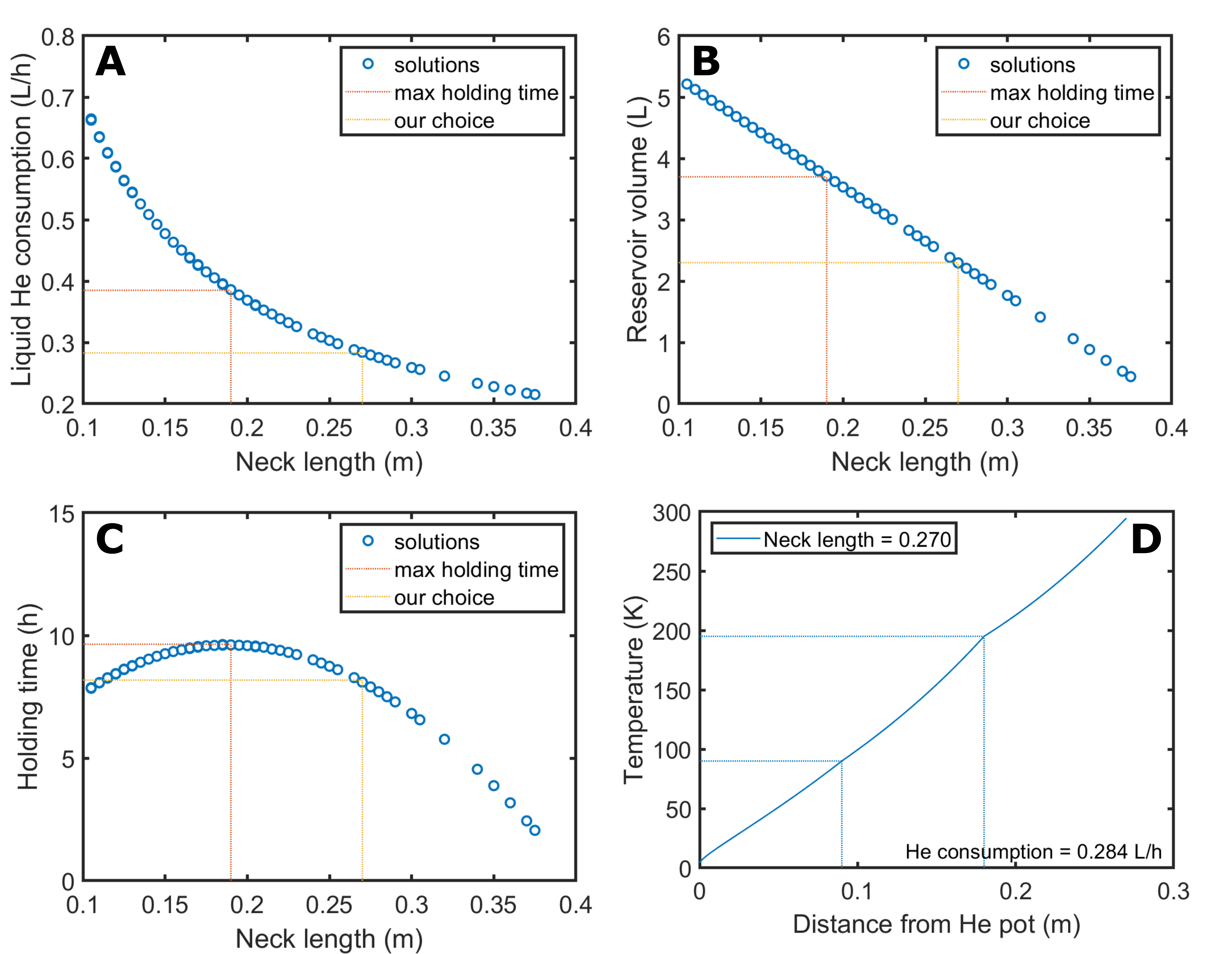
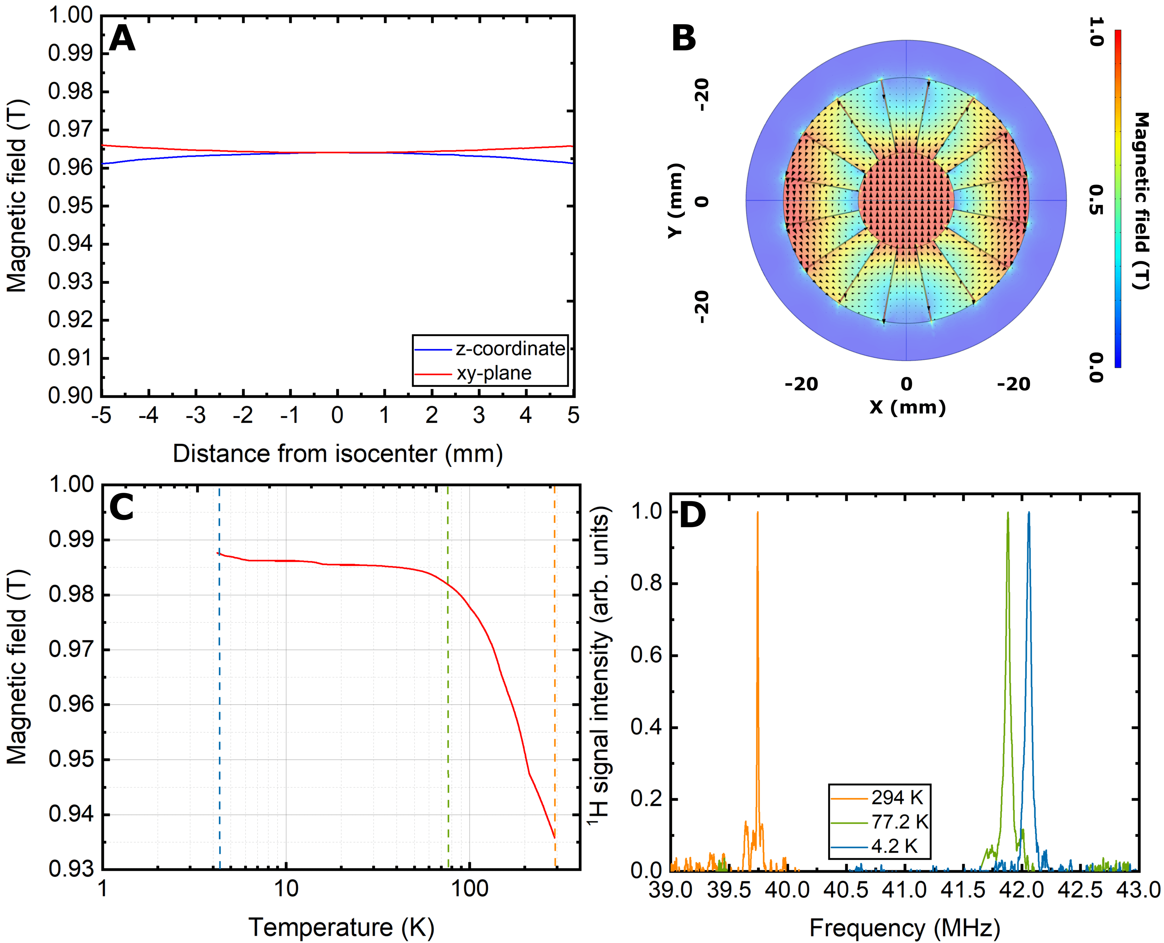
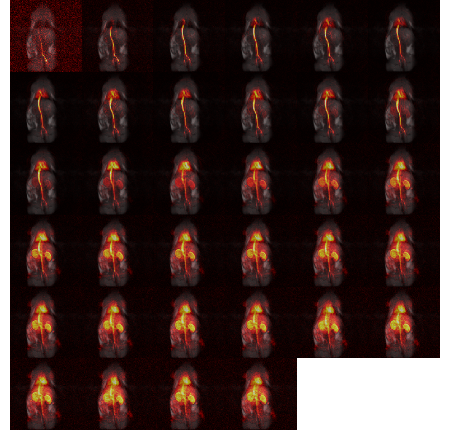
Figure 5. Rat angiogram: 40 images collected over 20 s; full-body coronal view; FOV 120 mm 120 mm; matrix size 120 x 120.