3738
Design of a high power RF amplifier with configurable number of channels1Paul C. Lauterbur Imaging Research Center, Shenzhen Institutes of Advanced Technology, Shenzhen, China, 2Key Laboratory for Magnetic Resonance and Multimodality Imaging of Guangdong Province, Shenzhen, China, 3Shanghai United Imaging Healthcare, Shanghai, China, 4Department of Biomedical Engineering, State University of New York at Buffalo, New York, NY, United States
Synopsis
Keywords: RF Arrays & Systems, Parallel Transmit & Multiband, RF power amplifier
UHF (Ultra high field) MRI requires high RF power from RF Power Amplifier (RFPA), especially for whole-body imaging1. Some studies on body imaging reported limitation on available RF power. In this study, we present works to provide RFPA with highest peak power capability known for UHF MRI with configurable number of transmit channels so as to meet different RF coil requirements. Feasibility and performance of the new method in UHF MRI was demonstrated on the bench and 5T whole-body scanner.Introduction
Parallel transmission (pTx) was developed for UHF MRI to improve the B1 homogeneity. To facilitate pTx, the number of available Tx channels are usually 8~16, the peak power per channel was not more than 2kW with total available RF power not more than 32kW 2-4, some studies on body imaging reported limitation on available RF power2,5. MRI scanners are used with different RF transmit coil array configurations, there were also studies on the impact of number of pTx channels or different shimming modes6. These applications place different demands on the number of channels or peak RF power per channel.This work presents a RFPA design method that supports pTx with highest peak power capability (64kW) known for UHF MRI. High utilization of RF power can be obtained when number of Tx channels are configured into 8/4/2. Body images are acquired to demonstrate the functionality of this new technology.
Method
In this study, the RFPA consists of power supply unit, RF power units(RFPU), control unit, Tx selection unit and power combiner unit1. Figure 1(A) shows the picture of the RFPA.The power supply unit converts the three-phase AC power into the DC power required by control unit and RFPUs. The control unit configures and monitors the operation status of RFPUs and power supply unit. Each RFPU contains 2 independent amplifier modules, each with power capability of 8kW. The final amplification stage of each amplifier module contains 4 Metal Oxide Semiconductor Field-Effect Transistors (MOSFETs), whose power is combined by a 4-to-1 Wilkinson combiner. The matching circuit of each MOSFET is shown in Figure 1(B).
The RFPU output power flow is configured by Tx selection unit, which can optionally connect the RFPU outputs to the power combiner unit or directly to the RFPA output terminals. Tx selection unit contains 8 identical RF switch modules, The schematic of RF switch module are shown in Figure 1(C).
The power combiner unit consists of six 2-to-1 Wilkinson combiner modules, the connection between them are variable. The introduction of the Tx selection unit and power combiner unit makes the number of RFPA’s output channels configurable between 8/4/2.
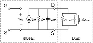
MOSFETs and the corresponding impedance matching circuits are critical to RFPA power capability. Figure 2 shows an equivalent circuit model of RF MOSFET and the load impedance.
When designing impedance matching circuit, the theoretical load impedance seen from the transistor current generator can be calculated using equations below.
$$R_{\text{Load}} = \frac{{(\frac{{V_{\text{DC}} - V}_{K}}{\sqrt{2}})}^{2}}{P_{\text{sat}}}$$
$$X_{\text{Load}} = \frac{1}{\omega \bullet C_{\text{oss}}}$$
Where Vdc is the DC drain-source voltage and Vk is turn-on voltage, Psat is the MOFET’s saturation output power.
The load impedance seem from transistor’s current generator can’t be measured directly. The equations can serve as a good start point for load-pull and optimization procedure if power capability or efficiency can’t meet the requirement. In this work, the peak power for each MOSFET (MRFX1K80H, NXP, The Netherlands) is tuned to be 2.5kW with output impedance of 1.4-j0.3Ohm and drain voltage of 75Vdc, the actual peak power is higher than rated power(1800W) declared in the device manual.
Results
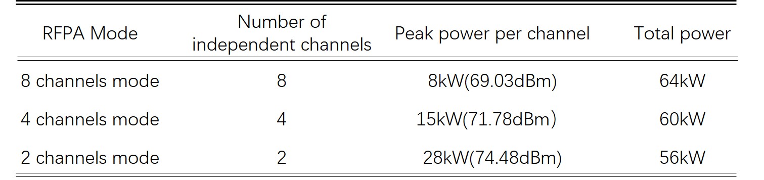
A. Bench testThe RFPA peak power capability is tested when configured to 8/4/2 channels modes, the test results are shown in table 1.
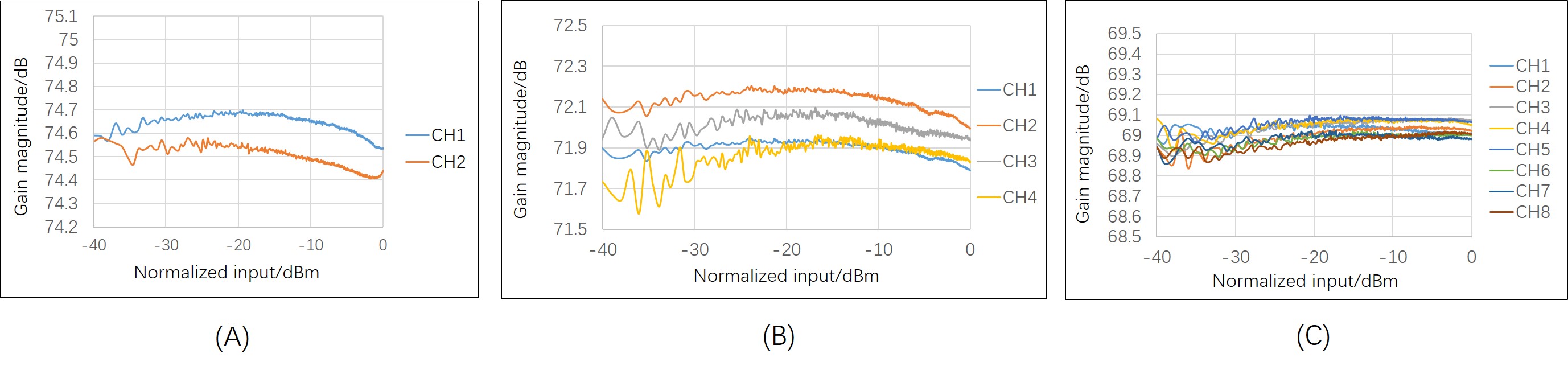
A digital pre-distortion(DPD) algorithm is developed to compensate the nonlinear characteristic of the RFPA. Figure 3 shows the RFPA linearity when RFPA is configured into different modes. Though the gain fluctuation is slightly influenced by the operation modes, the gain fluctuation per channel is less than 0.3dB respectively, high linearity is accomplished over wide dynamic range.
B. Scanner test
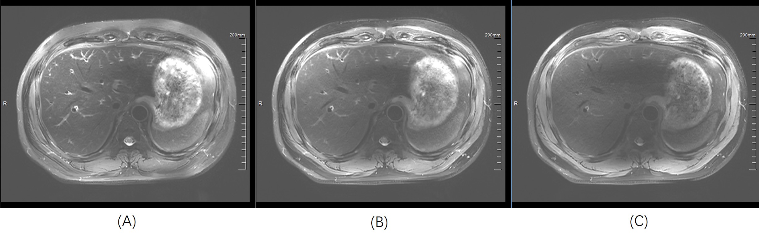
Some studies on body imaging reported limitation on peak B1 field, higher RF power is needed even for local transmission. In this work, Images of the abdomen are acquired on a 5T whole-body scanner (uMR Jupiter, United Imaging Healthcare, Shanghai, China) with bore sized 8-channel(8 ch) volume transmit coil and 24ch local receive coil.
Body images are acquired using FSE sequence. Figure 4 shows images of abdomen when RFPA peak power is set to 64kW(8kW*8ch), 32kW(4kW*8ch) and 16kW(2kW*8ch).
Conclusion
RFPA with highest power capability known for UHF MRI is designed and demonstrated in a 5T whole-body scanner. The number of RFPA output channels can be configured between 8/4/2. High linearity over a wide dynamic range is demonstrated when RFPA is configured into different modes. Body images acquired in the 5T scanner demonstrate the feasibility of the new method proposed in this study, this new method can also be applied in other UHF systems such as 7T scanner, the addition of more channels can be achieved straightforwardly.Acknowledgements
This work is supported by National Key Research and Development Program of China, 2021YFE0204400; the Strategic Priority Research Program of Chinese Academy of Sciences, XDB25000000; National Natural Science Foundation of China, U22A20344; Youth Innovation Promotion Association of CAS No. Y2021098; Key Laboratory Project of Guangdong Province, 2020B1212060051; Shenzhen city grant, RCYX20200714114735123.References
1. Chen JF, Li Y, Zhang H, et al. High power RF amplifier for UHF MRI with configurable number of channels. ISMRM 2021 Abstract 1585.
2. Erturk MA, Li X, Van de Moortele PF, et al. Evolution of UHF Body Imaging in the Human Torso at 7T: Technology, Applications, and Future Directions. Top Magn Reson Imag. 2019;28:101-124.
3. Gudino N, de Zwart JA, Duyn JH. Eight‐channel parallel transmit‐receive system for 7 T MRI with optically controlled and monitored on‐coil current‐mode RF amplifiers. Magn Reson Med. 2020;00:1-8.
4. Orzada S, Solbach K, Gratz M, et al. A 32-channel parallel transmit system add-on for 7T MRI. PLoS One. 2019;14: e0222452.
5. Keith GA, Rodgers CT, Hess AT, et al. Automated Tuning of an Eight-Channel Cardiac Transceive Array at 7 Tesla Using Piezoelectric Actuators. Magn Reson Med. 2015;73:2390–2397.
6. Guerin B, Gebhardt M, Serano P, et al. Comparison of Simulated Parallel transmit Body Arrays at 3 T Using Excitation Uniformity, Global SAR, Local SAR, and Power Efficiency Metrics. Magn Reson Med. 2015;73:1137–1150.
Figures
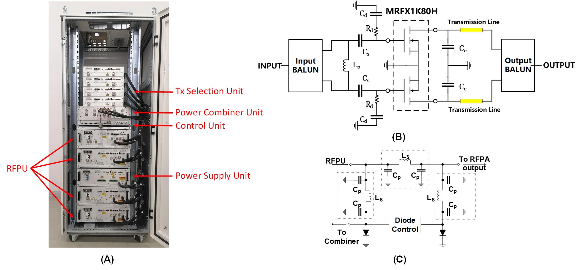
Figure 1: (A)Photo of Multi-channel RFPA. (B)Power unit circuit in RFPU. (C)RF Switch Module in the Tx Selection Unit.