3735
Stretchable conductive-thread MRI receive array coils for the knee1Elmore Family School of Electrical and Computer Engineering, Purdue University, West Lafayette, IN, United States, 2Weldon School of Biomedical Engineering, Purdue University, West Lafayette, IN, United States, 3Radiology and Medical Imaging, University of Virginia, Charlottesville, VA, United States
Synopsis
Keywords: RF Arrays & Systems, New Devices, Coils, Stretchable
We report on the development of an 8-channel stretchable array coils for 3T knee MRI which was rapidly designed using embroidered conductive threads on athletic fabric. The coil is omnidirectionally stretchable and conforms to the anatomy. Phantom testing shows the coil’s signal-to-noise ratio (SNR), and image quality are comparable to a commercial flexible coil. In vivo imaging was done on a healthy volunteer illustrates the potential of rapidly developed stretchable coils.
Introduction
Most receiver arrays in clinical settings are rigid and designed to work with all patients hence often mismatching to any particular patient’s size. There has been a shift towards flexible and stretchable receive coil technology1-3, which is conforming to the anatomy, providing an increase in the signal-to-noise ratio (SNR). Prototypes of application-specific flexible coils have been developed4-7, but these designs are still limited in their conformability, employ novel materials, difficult to manufacture quickly, and are not currently practical in the clinical setting. Our group previously proposed a stretchable receive array using silver conductive threads sewn on athletic fabric8,9 which is entirely stretchable and can conform to curved surfaces like bespoke garments.Extending on our previous work, we designed and built an 8-channel stretchable array for knee imaging using a custom-fabricated stretchable tinsel copper thread on athletic fabric. The coil elements are stitched using an embroidery machine allowing for rapid and low-cost development of the coils while delivering comparable performance compared to conventional commercial coils.
Methods
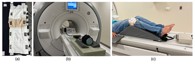
Conductive silver-coated thread (C3406G22YA, Maeden Innovation, Taiwan) was stitched onto stretchable elastane fabric (7KW18XST, The Moore Company, Rhode Island, USA). The threads have an outer diameter of 0.32 mm and a DC resistance of 1.43 Ω/m. The fabric is an 81% 40/34 Nylon, 19% 40 denier spandex Tricot fabric with a maximum stretch of 150%. Stitching was done on the Innovis VE2200 embroidery machine (Brother Industries, Japan). Each element is a square loop 10 x 5.5 cm (Fig 1a). The coil is segmented longitudinally using a printed circuit board (PCB) for the tune, match, and active detuning circuit. The matching network uses an LC lumped element lattice balun. Individual coil elements were decoupled and attached using hook-and-loop fasteners. A 3D printed floating cable trap10 was used to remove common-mode currents in the cable shields.The coil tuning, matching, detuning, and decoupling performance on the bench was done using a network analyzer (E5071C, Keysight Technologies, USA), which was utilized to tune-and-match the coil (S11 better than -30 dB at the 3 T Larmor frequency of 127.7 MHz) and to measure the Q factor (S21 3-dB method). Phantom imaging was done on a cylindrical NiSO4 phantom (Siemens Medical Solutions, USA) using the GE Discovery MR750 3T MR scanner through a receiver gateway box (Clinical MR Solutions, USA) (Fig 1b). A gradient echo sequence (Axial, TE = 1.86 ms, TR = 400 ms, FOV 14 x 14 cm, Slice thickness = 4 mm, Averages = 1, Flip angle = 42°, Scan time = 1:37 min) was used for SNR comparison. A commercial GE 16-channel large flexible coil (GE Medical Systems, USA) was used as a benchmark for SNR analysis. Signal and noise regions of interest (ROIs) were calculated using in-house code following the Method 4 prescribed by NEMA MS1-2008 (R2014)11.
Following IRB approval and informed consent, in-vivo testing was done on a healthy male volunteer’s knee. The Gradient echo sequence (Sagittal, TE = 9.08 ms, TR = 826 ms, FOV 18 x 18 cm, Slice thickness = 3 mm, Averages = 2, Flip Angle = 111°; Axial, TE = 9.22 ms, TR = 617 ms, FOV = 18 x 18 cm, Slice thickness = 5 mm, Averages = 2, Flip Angle = 111°) was used. The volunteer’s knee is placed at a 15-degree flexion angle and the coil wrapped around and affixed using hook-and-loop (Fig 1c).
Results
Manufacturing processThe stitching process on the embroidery machine took 26 seconds per coil element, taking a total of 208 seconds (3.5 minutes) to fabricate 8 elements. The tune, match, and assembly process took 3 hours. At the end of the process, the coils were able to be imaged at the scanner.
Phantom testing
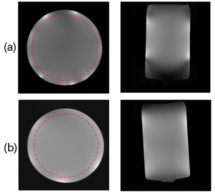
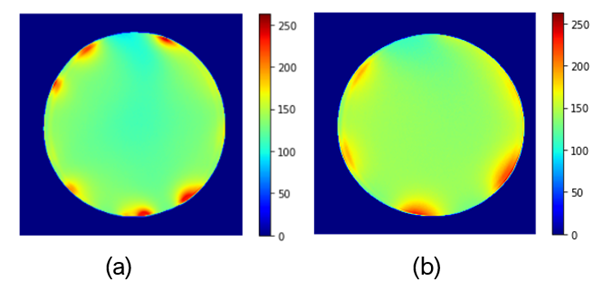
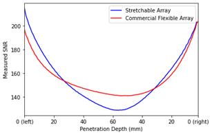
Fig 2 shows the resulting MR images obtained from the gradient echo sequence, and Fig 4 shows the SNR maps for our stretchable array and the commercial flexible coil. The signal region for SNR was determined on the axial image by taking the mean of the phantom interior, excluding the outer edge (10 mm) as prescribed by NEMA11. The SNR was 129.79 for our stretchable array and 137.93 for the commercial coil. Fig 4 measures the local SNR as a function of penetration depth.
In vivo testing
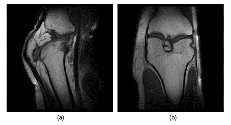
Fig 5. Shows sagittal and coronal images of the knee at 15-degree flexion obtained using our 8-channel stretchable coil.
Conclusion and Discussion
This work illustrates the performance of a rapidly prototyped 8-channel stretchable coil array. While there is room for SNR improvements, the prototype presents a solution comparable in image quality to commercial coils. In vivo scans illustrates that the stretchable coil can conform closely to the individual’s anatomy and provide detailed anatomical images under both stretch and compression. This work also demonstrates MR coils can be customized to closely fit to any anatomy thus improving comfort and imaging quality for patients and radiologists. Although this study focused on the knee, the same setup could be used for other anatomies such as the foot, ankle, neck. Future studies include coil characterization, analyzing the performance in parallel imaging, determining the stretching and compression effects on SNR, and the effects of stitch patterns.Acknowledgements
The authors would like to thank Oni Chen and his team at Maeden Innovation for their support in providing the conductive threads. The authors also thank Purdue’s MRI technologist Nathan Ooms R.T.(R)(MR) for help with in vivo scan sequences.References
1. Sekitani T, Noguchi Y, Hata K, et al. A rubberlike stretchable active matrix using elastic conductors. Science. 2008; 321:1468–1472.
2. Port A, Luechinger R, Albisetti L, et al. Detector clothes for MRI: A wearable array receiver based on liquid metal in elastic tubes. Sci Rep. 2020;10(1):10:1–10.
3. Ruytenberg T, Webb A, Zivkovic I. Shielded-coaxial-cable coils as receive and transceive array elements for 7T human MRI. Magn Reson Med. 2020;83:1135–1146.
4. Hosseinnezhadian S, Frass-Kriegl R, Goluch-Roat S, et al. A flexible 12-channel transceiver array of transmission line resonators for 7 T MRI. J Magn Reason Imaging. 2018;296:47–59.
5. Jia F, Yuan H, Zhou D, Zhang J, Wang X, Fang J. Knee MRI under varying flexion angles utilizing a flexible flat cable antenna. NMR Biomed 2015;28:460–467.
6. Motovilova E, Tan ET, Taracila V, et al. Stretchable self-tuning MRI receive coils based on liquid metal technology (LiquiTune). Sci Rep. 2021;11:1–10.
7. Collick BD, Behzadnezhad B, Hurley SA, et al. Rapid development of application-specific flexible MRI receive coils. Phys Med Biol. 2020;65:19-20.
8. Vincent JM, Rispoli JV. Stitching stretchable radiofrequency coils for MRI: A conductive thread and athletic fabric approach. Annu Int Conf IEEE Eng Med Biol Soc. 2019:6798–6801.
9. Vincent JM, Gim M, Rispoli JV. Elastically stretchable and flexible RF receive coils for magnetic resonance imaging. Int. Conf. Electromagn. Adv. Appl. 2021:319.
10. Enriquez AG, Vincent JM, Rispoli JV. Dual-tuned removable common-mode current trap for magnetic resonance imaging and spectroscopy. Conf Proc IEEE Eng Med Biol Soc; 2019:6802.
11. NEMA Standards Publication MS 1-2008 (R2014) Determination of Signal-to-Noise Ratio (SNR) in Diagnostic Magnetic Resonance Imaging. 2014.
Figures