3734
Toward a Size-Adaptable 128-Channel Receive RF Coil for Human Head Imaging at 3T Using a Flexible Plate Approach
William Mathieu1, Charbel Matta1, Milica Popović1, and Reza Farivar2
1Electrical and Computer Engineering, McGill University, Montreal, QC, Canada, 2Ophthalmology, McGill University, Montreal, QC, Canada
1Electrical and Computer Engineering, McGill University, Montreal, QC, Canada, 2Ophthalmology, McGill University, Montreal, QC, Canada
Synopsis
Keywords: RF Arrays & Systems, RF Arrays & Systems
We present a size-adaptable flexible-plate 128-channel receive coil design with initial results. Our approach allows for increased element density as elements can be placed closer to the surface of the scalp. Arrays are built on semi-flexible plates with boundaries roughly following cranial sutures. The aim is to accommodate at least 99% of head shapes and sizes. Our 18-channel “occipital” plate array (1 of 8 plates) was compared to the posterior portion (40-channels) of the Siemens 64 Head/Neck coil using SNR maps. Results show that our design improves average and max SNR by 1.9- and 7.4-fold, respectively.Introduction
Image quality in MRI is heavily dependent on the proximity of receptive elements to their target volume. The long-standing design paradigm in receive-only coils is a phased-array which necessitates a rigid body design to ensure maximum stability to support the highest possible element count1-4. This one-size-fits-all approach may improve the signal-to-noise ratio (SNR) for a head which happens to perfectly fit the rigid shell, however this is seldom the case. The advantages that a high channel count coil provides are squandered if the shape of the coil does not optimally fit a given head. Our design aims to decrease element diameters to the extent that SNR is maximized. However, in doing so, the receptive fields of elements decrease, an effect that can be offset by maximizing filling factor, which we achieve through flexible, movable plates. On these plates generic phased arrays are constructed, and between plates we employ bending elements on ultra-flexible film. Our goal is to construct a coil which comfortably fits any adult head shape and size to the 99th percentile, and in doing so eliminating any SNR-gap between individuals. Here we present the design of the complete 128-channel coil, and the performance of a single “occipital” plate, compared to a commercial Siemens head coil.Methods
An average human head model was used as the initial shape from which flexible plates were partitioned. Plate boundaries roughly follow the locations of the cranial sutures. Boundaries were then adjusted for ideal coverage of the brain and optimal element tessellation; an early iteration is shown in Figure 1a. The final configuration is shown in Figure 1b, which features 8 plates (eye plate not seen). Plates were 3D printed in flexible thermoplastic polyurethane (TPU) material. To fulfill the requirement of 128 channels, with the consideration of ensuring adequate signal at cortical depths, element diameters were set at 36-mm. Each plate is attached to a non-magnetic pneumatic piston, which moves the plate into position, normal to the surface of the head, see Figure 1c and d. To fill the gaps between plates, bending elements constructed on thin film will be employed, outlined in previous work5. The pistons, plates, and circuitry are supported by an outer shell, seen in Figure 1e, which plugs into the patient table of a standard 3T clinical Siemens Prisma scanner (Siemens Healthineers, Erlangen, Germany). A standard element receive-only circuit was employed, shown in Figure 2(a). Elements were tuned, matched, and preamps were decoupled using standard methods6 with a 2-port vector network analyzer (Copper Mountain Technologies, Indianapolis, USA). Given the limited surface area of the plates, all electrical components, excluding capacitors CT and C1, were placed on vertical printed circuit boards (PCBs), normal to the surface of the plates, two such boards are shown in Figure 2c. Each board supports two element circuits, one on each side. To secure elements to the plates while allowing them to move with different head shapes and sizes, loop wires were passed through the plates, turning the plates into a substrate for the coil circuits. Four such elements constructed in this way are shown in Figure 2b and c, corresponding to the outside and inside surfaces of a plate, respectively. MRI experiments were conducted using the Siemens Prisma. The occipital portion of our coil, see Figure 3, was tested against the posterior section of a Siemens 64 Head/Neck coil (40-channels). A standard 1.9-L Siemens bottle phantom was used. An integrated calculation environment (ICE), IceMGHCoilArrayReconUtil, for RF coil quality evaluation was provided by the Martinos Center for Biomedical Imaging (MGH Department of Radiology, Harvard Medical School)7. The environment outputs optimally combined SNR maps and channel noise covariance matrices. The SNRMap sequence had the following scanner parameters: TE = 6 ms, TR = 30 ms, FOV = 383 mm × 383 mm, slice-thickness = 5 mm, orientation = transversal, BW = 395 Hz/Pixel, averages = 4, and FA = 10o.Results and Discussion
Figure 4 shows the SNR performance comparison between the two tested coils. All SNR maps were windowed to 150 units. For both the average and maximum values the occipital array outperforms the Siemens 64 Head/Neck. As reported in Figure 4, average and max SNR values, were 12 and 135 for the Siemens coil, and 23 and 998 for our occipital coil. Despite the higher element count, the Siemens coil is limited by its inability to conform to the shape of the bottle phantom. Channel noise correlation matrices were also collected, see Figure 5, showing higher overall noise in the occipital array. Average channel noise correlations were nnn for the siemens coil and mmm for the occipital array.Conclusion
Channel count has been limited by the inability to place small elements close enough to their sample. The results presented here show that our approach, using semi-flexible plates, allows for smaller element loop diameters leading to higher SNR without sacrificing sample coverage.Acknowledgements
I'd like to thank my supervisors Reza Farivar and Milica Popović and my colleague Charbel Matta. I'd also like to thank Gerald Moran at Siemens Healthineers for his continual support of the project. This project was financially supported by Mitacs in partnership with Siemens Healthineers and MEDTEQ+.
References
- Farivar, R., Grigorov, F., van der Kouwe, A.J., Wald, L.L. & Keil, B. Dense, shape‐optimized posterior 32‐channel coil for submillimeter functional imaging of visual cortex at 3T. Magnetic resonance in medicine 76, 321-328 (2016).
- Ghotra, A., et al. A size‐adaptive 32‐channel array coil for awake infant neuroimaging at 3 Tesla MRI. Magnetic Resonance in Medicine 86, 1773-1785 (2021).
- Keil, B., et al. A 64‐channel 3T array coil for accelerated brain MRI. Magnetic resonance in medicine 70, 248-258 (2013).
- Wiggins, G.C., et al. 96‐Channel receive‐only head coil for 3 Tesla: design optimization and evaluation. Magnetic Resonance in Medicine: An Official Journal of the International Society for Magnetic Resonance in Medicine 62, 754-762 (2009).
- Mathieu, W., Popović, M. & Farivar, R. Towards Brain MRI Adaptable to Head Size: Bowing RF Coil Phased Arrays. IEEE Journal of Electromagnetics, RF and Microwaves in Medicine and Biology (2021).
- Keil, B. & Wald, L.L. Massively parallel MRI detector arrays. Journal of magnetic resonance 229, 75-89 (2013).
- Polimeni, J.R. & Wald, L.L. Documentation for icemghcoilarrayreconutil software. (Harvard Medical School, 2009).
Figures
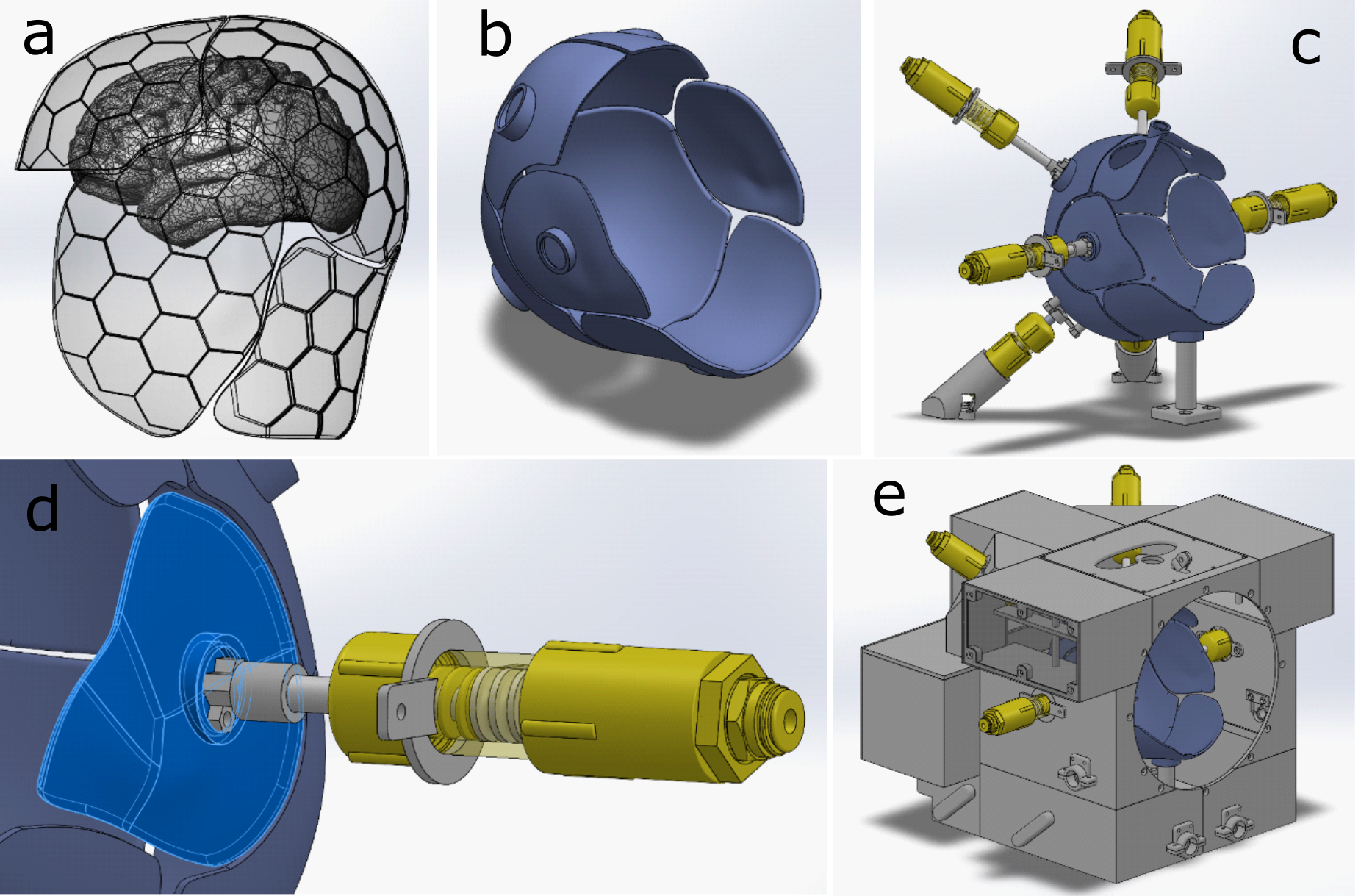
Figure 1: Mechanical
design. (a) initial plate boundaries. (b) final plate design. (c) non-magnetic
pistons supporting plates. (d) close-up of "ear" plate piston. (e)
Supportive shell structure.
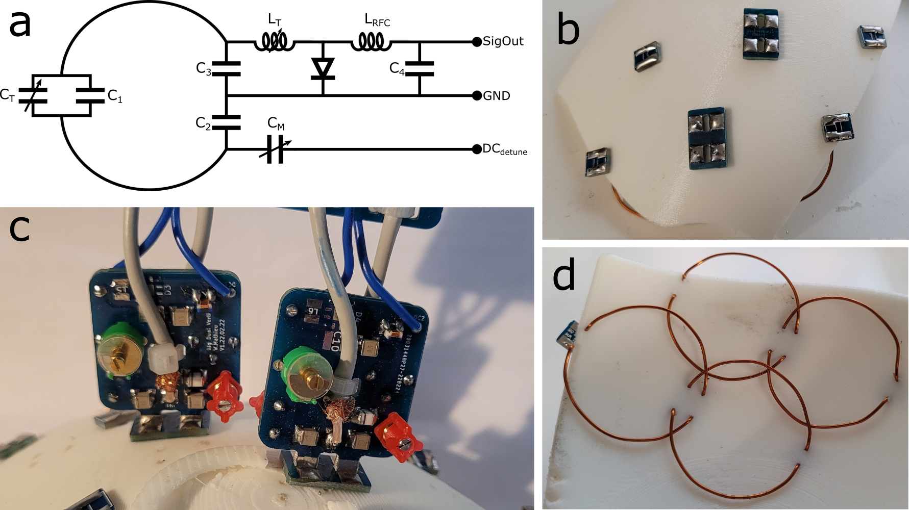
Figure 2: Electrical
building methods of coil elements. (a) coil
element circuit. (b) outside view of four elements supported by rubber plate. (c)
vertical PCBs on which most of the element circuit is supported. (d) underside
of elements shown in b.
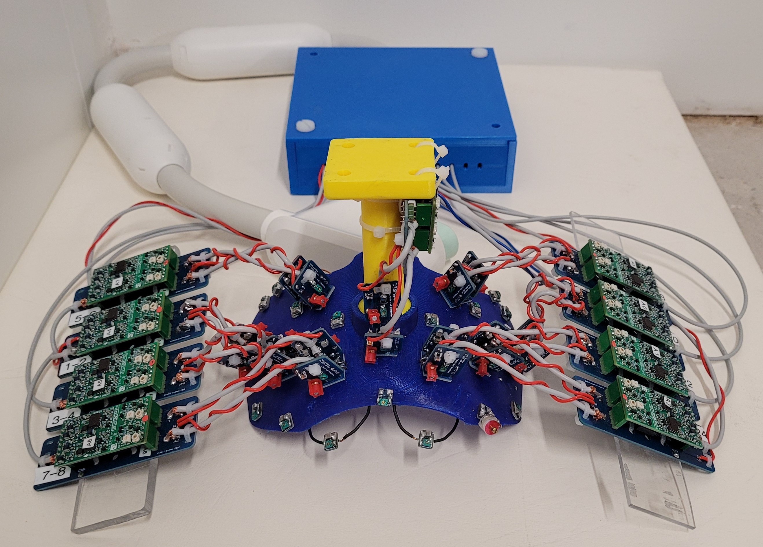
Figure 3: 18-channel
occipital section of 128-channel array.
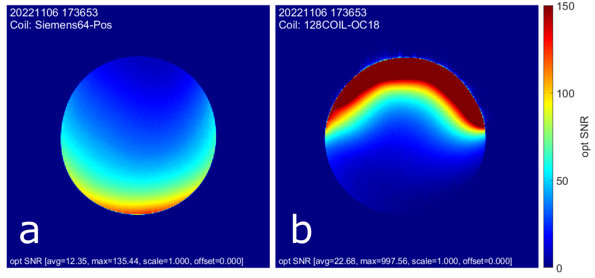
Figure
4: SNR results comparing performance of (a)
posterior section of Siemens Head/Neck 64, with (b) 18-channel occipital
section of 128-channel coil. Note that the occipital array was placed on the anterior
of the bottle phantom.
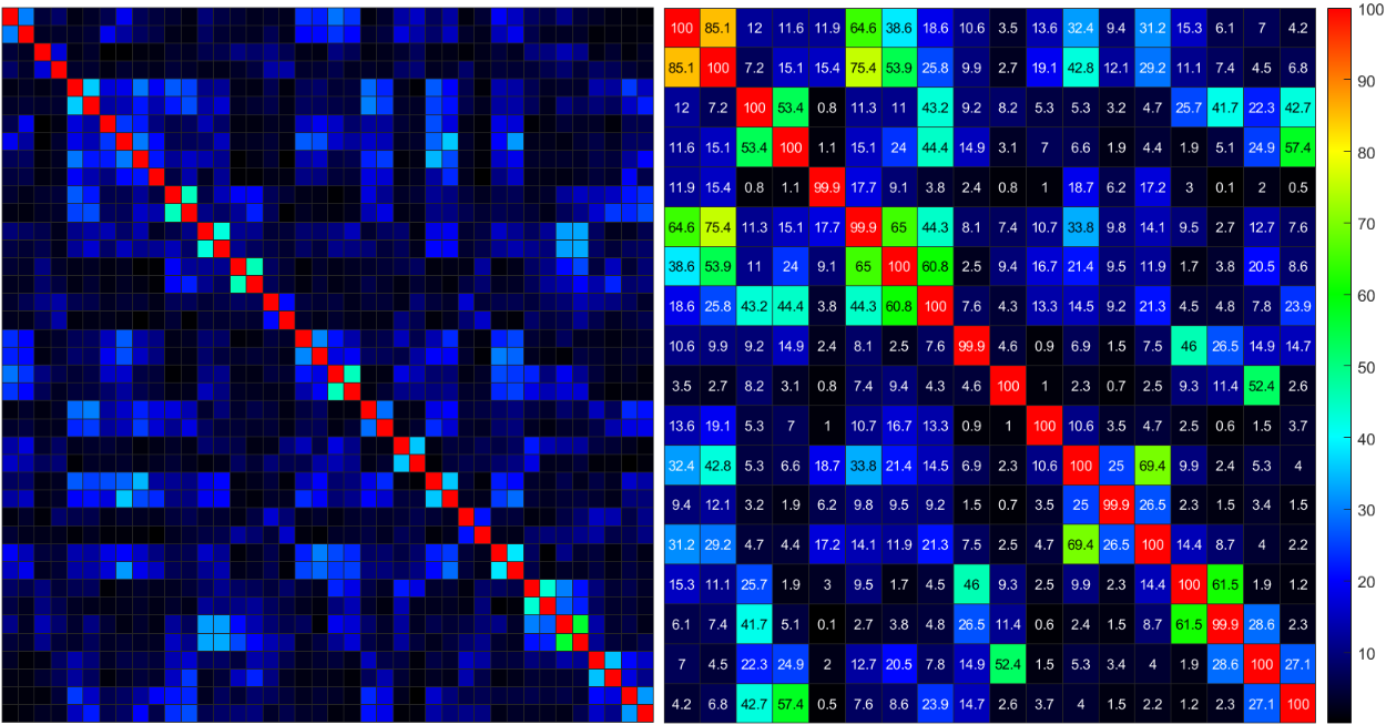
Figure 5: Channel noise covariance matrices of (left) posterior section of Siemens Head/Neck 64, with (right) 18-channel
occipital section of 128-channel coil.
DOI: https://doi.org/10.58530/2023/3734