3732
Stretchable Coil for Small Animal MRI
Thejas Vishnu Ramesh1, Folk W. Narongrit2, and Joseph V. Rispoli1,2,3
1Biomedical Engineering, Purdue University, West Lafayette, IN, United States, 2Electrical and Computer Engineering, Purdue University, West Lafayette, IN, United States, 3Radiology and Medical Imaging, University of Virginia, Charlottesville, VA, United States
1Biomedical Engineering, Purdue University, West Lafayette, IN, United States, 2Electrical and Computer Engineering, Purdue University, West Lafayette, IN, United States, 3Radiology and Medical Imaging, University of Virginia, Charlottesville, VA, United States
Synopsis
Keywords: Non-Array RF Coils, Antennas & Waveguides, Non-Array RF Coils, Antennas & Waveguides, Small Animal MRI
This work demonstrates a simple, easy to use, stretchable coil system for small animal MRI at 7T. Phantom images obtained using the stretchable coil were analysed for coil SNR. The SNR of the stretchable coil was compared with SNR of a standard commercial coil. Ex-vivo imaging of a mouse and rat brain was also performed. Current work involves minimizing SNR reduction due to coil stretch. Future work involves developing a 4-channel stretchable coil array for in-vivo imaging of a rat brain.
Purpose
To illustrate the application of stretchable coils for small animal MRI involving a simple plug-n-play system that can be used to interface custom 1H surface arrays to the Bruker 7T scanner.Introduction
Stretchable coils conform to the anatomy of interest thus providing an increase in SNR1. Advancements in both material and application of stretchable coils have been focused on human MRI 2-3. Stretchable coils for small animal MRI have not yet been explored even though drug and device testing happen first in small animals before human trials. In this work, we explore the application of a single channel stretchable coil for small animal imaging at 7T. This work illustrates the first-time stretchable coil technology has been translated for small animal MRI.Methods
The in-house developed receive system consists of three main components: the coil with a floating cable trap, the preamplifier board that contains preamplifier and DC supply PCBs, and the D-Sub board for interfacing to the scanner.Coil: The coil was designed based on the conductive thread on fabric technique2. The 3.5cm x 3.5cm coil was tuned to 300.3±0.3MHz, the Bruker BioSpin 7T scanner Larmor frequency, along with a π-matching network. A 3D printed cable trap4 was used to suppress common mode currents along the length of the cable. The coil and its corresponding schematic are shown in Figure 1.
Pre-amplifier Board: The preamplifier board was divided into two parts, the pre-amplifier circuit and the DC supply base board. The open-source preamplifier design from the UMC Utrecht High Field MRI group5 was adapted to be interfaced with the Bruker Avance III RF adapter. The preamplifier board was placed on top of a DC supply board that provided the DC biasing voltages of +10V for the amplifier and +5V with 100mA for the PIN diode detuning circuit.
D-sub Board: The D-sub board was used to interface the coil to the Avance III RF interface adapter in the scanner. It houses a D-sub plug at one end for the scanner interface while the other end is routed to the pre-amplifier board. An external potentiometer was incorporated in the detuning bias line to regulate the current required for detuning. The preamplifier and D-sub board are shown in Figure 2.
Experiment: T1 FLASH (TE = 3.5ms, TR = 200ms, Averages = 5, α = 30o, Slice Thickness = 3mm, Image Size = 384 x 384, FOV = 30mm x 30mm, Scan Time = 4m16s) and T2 Turbo RARE (TE = 33ms, TR = 2500ms, Averages = 2, Echo Spacing = 11ms, Rare factor = 8, Slice Thickness = 3mm, Image size = 256 x 256, FOV = 30mm x 30mm, Scan Time = 2m40s) images of the Bruker 1H IM Rat Head phantom as shown in Figure 3 were obtained for SNR analysis. These values were then compared with SNR values from images obtained using a 3.5cm diameter Bruker surface coil. Ex-vivo mouse and rat brain images in Figures 4 and 5 were acquired using T1 FLASH (TE = 3.73ms, TR = 200ms, Averages = 9, α = 30o, Slice Thickness = 2.5mm, Image Size = 512 x 512, FOV = 40mm x 40mm, Scan Time = 10m15s), T1 RARE (TE = 9.27ms, TR = 2500ms, Averages = 3, Echo Spacing = 9.266ms, Rare Factor = 4, Slice Thickness = 2.5mm, Image Size = 512 x 512, FOV = 40mm x 40mm, Scan Time = 12m), and T2 Turbo RARE (TE = 51.92ms, TR = 2500ms, Averages = 2, Echo Spacing = 17.307ms, Rare Factor = 8, Slice Thickness = 2.5mm, Image Size = 512 x 512, FOV = 40mm x 40mm, Scan Time = 5m20s) sequences.
Results
The Qunloaded = 66.9 to Qloaded = 32.3 ratio of the coil was 2.1 with S11=-23.3dB. S21 change for detuning was 35dB which corresponds to a detuning resistance6 of 919.7Ω for 5% transmit B1 perturbation. The SNR of the T1 FLASH and T2 Turbo RARE phantom images were 8.39 and 7.14 respectively, which were 2x lesser than the commercial coil SNR. The rat brain images provided higher contrast between anatomical features when compared to mouse brain images.Discussion and Conclusion
Lower SNR of the stretchable coil is because the coil was fully stretched during the duration of the scan. Stretching causes linear increase in inductance which changes the resonance and the matching impedance between coil and the preamplifier, causing a degradation in SNR. Current work involves minimizing SNR loss as a function of stretch by utilizing Interdigital Capacitors (IDC) for tuning and matching. Greater anatomical accuracy was observed in ex-vivo rat brain images as the loading effect was greater compared to mouse brain. Ghosting artifacts were present in both the mouse and rat T1 FLASH images. Future work will be to develop a 4-channel stretchable coil array for in-vivo imaging of rat brain.Acknowledgements
- The authors would like to thank Dr. Mark Mattingly and Dr. Kristin Granlund from Bruker for their help in developing the coil configuration files and optimizing the system design.
- We would like to acknowledge Dr. Gregory Tamer Jr. for helping run the developed coil configuration files to test the coil.
- The authors would like to thank Mr. Oni Chen and the entire team at Maeden Innovation Co., Ltd. for developing the conductive thread that was used to design the coil in this project.
References
- Corea, Joseph R., et al. "Screen-printed flexible MRI receive coils." Nature communications 7.1 (2016): 1-7.
- Vincent, Jana M., and Joseph V. Rispoli. "Conductive thread-based stretchable and flexible radiofrequency coils for magnetic resonance imaging." IEEE Transactions on Biomedical Engineering 67.8 (2019): 2187-2193.
- Port, Andreas, et al. "Detector clothes for MRI: A wearable array receiver based on liquid metal in elastic tubes." Scientific reports 10.1 (2020): 1-10.
- Enríquez, Ángel G., Jana M. Vincent, and Joseph V. Rispoli. "Dual-tuned removable common-mode current trap for magnetic resonance imaging and Spectroscopy." 2019 41st Annual International Conference of the IEEE Engineering in Medicine and Biology Society (EMBC). IEEE, 2019.
- High field MRI group - UMC Utrecht (2021, November 24). Preamp-board. UMC Utrecht 7T Coillab. Retrieved March 1, 2022, from https://github.com/umcu7tcoillab
- Taracila,
Victor, Pei Chan, and Fraser Robb. "Minimal acceptable blocking impedance
for RF receive coils." Proceedings of the International Society for
Magnetic Resonance in Medicine. Vol. 18. 2010.
Figures
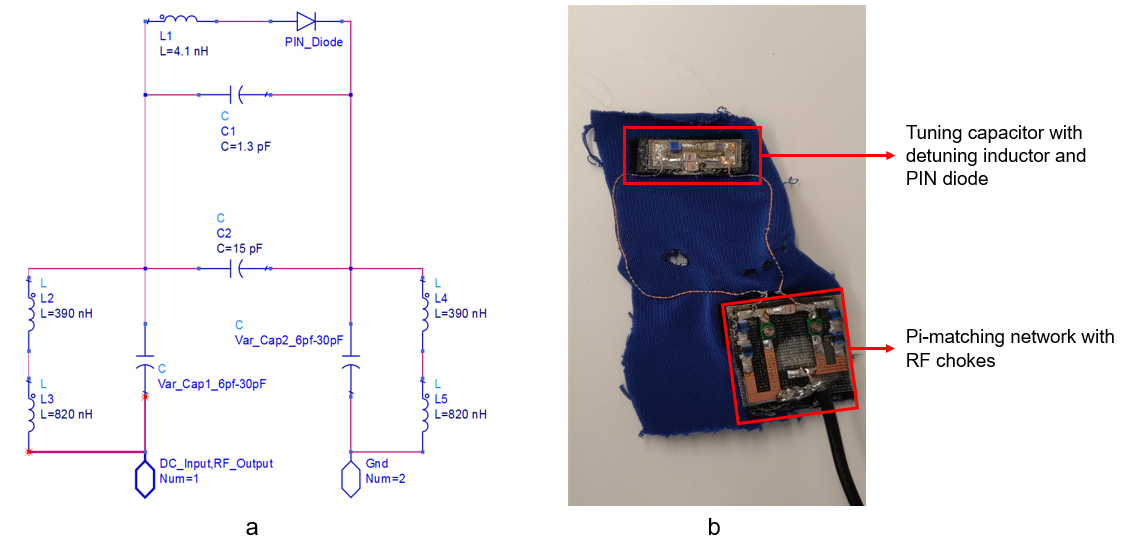
Figure 1. (a) Coil Schematic (b) The developed coil
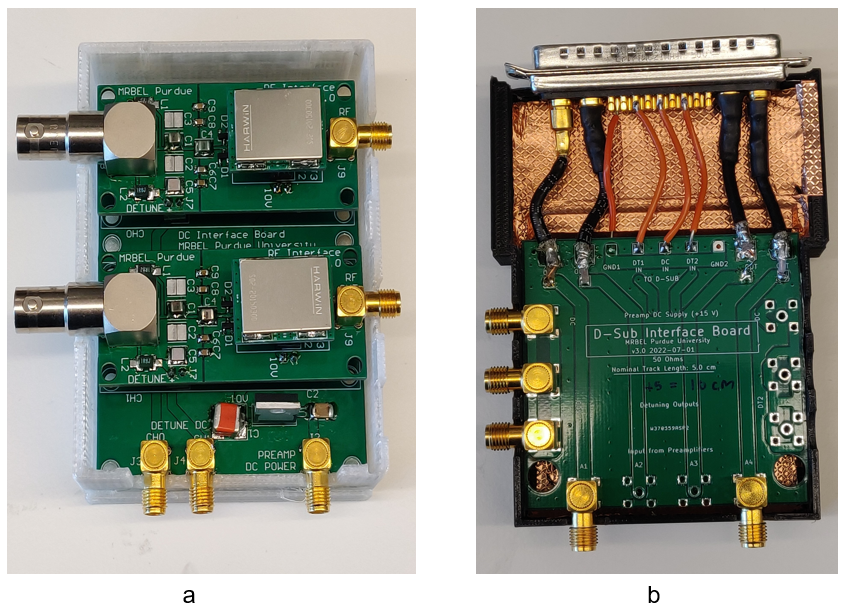
Figure 2. (a) The preamplifier board containing Pi/T decoupling networks and Bias-T for detuning. The base DC supply board provides the detuning and preamplifier bias voltages through a voltage regulator IC. (b) The D-Sub interface board.
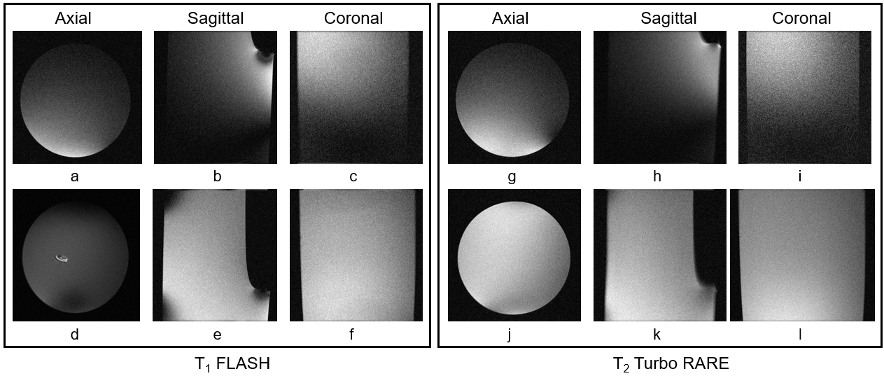
Figure 3. T1 FLASH images of the Rat Head Phantom from (a), (b), (c) stretchable coil and (d), (e), (f) Bruker coil. T2 Turbo RARE images from (g), (h), (i) stretchable coil and (j), (k), (l) Bruker coil.
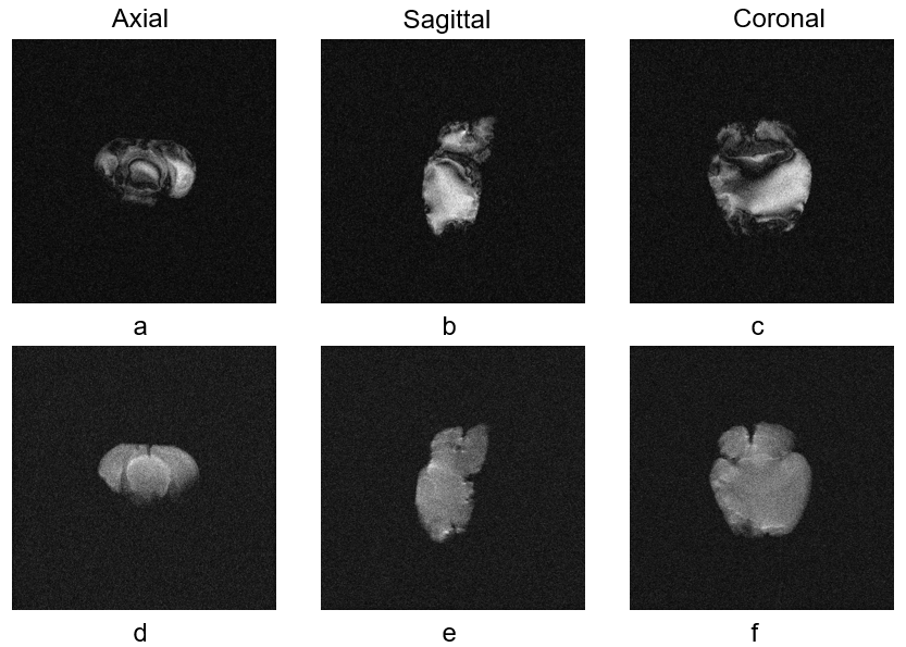
Figure 4. (a), (b), (c) T1 FLASH and (d), (e), (f) T1 RARE mouse brain images
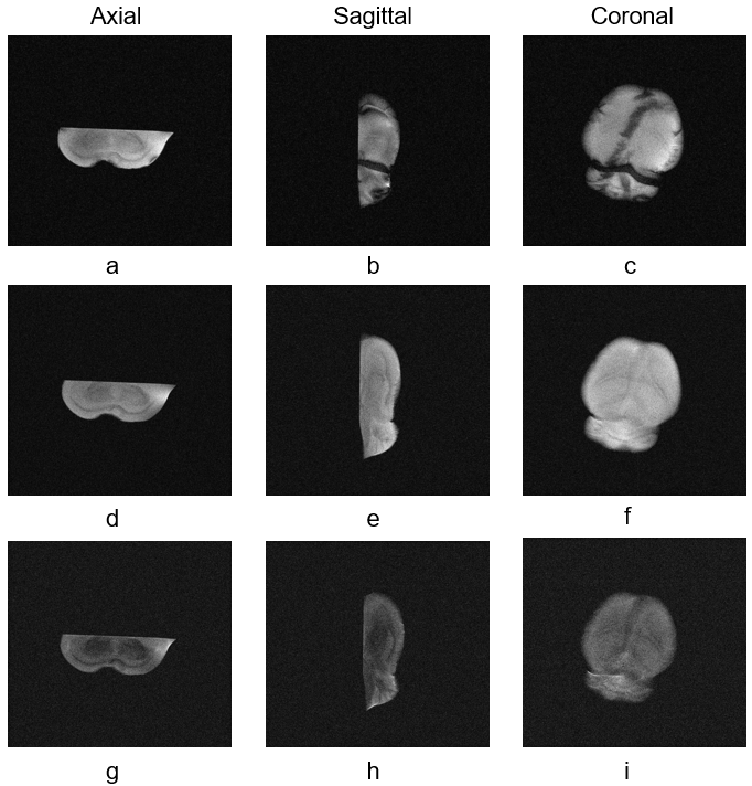
Figure 5. (a), (b), (c) T1 FLASH, (d), (e), (f) T1 RARE and (g), (h), (i) T2 Turbo RARE images of rat brain.
DOI: https://doi.org/10.58530/2023/3732