3730
Twisted pair coils as flexible receive elements for 7 T - SNR and active detuning efficiency1High Field MR Center, Center for Medical Physics and Biomedical Engineering, Medical University of Vienna, Vienna, Austria
Synopsis
Keywords: Non-Array RF Coils, Antennas & Waveguides, Non-Array RF Coils, Antennas & Waveguides, Flexible RF Coils
Form-fitting coil designs demand highly flexible coils such as twisted pair or coaxial transmission line resonators. Both of these designs and respective interfacing circuits were investigated as receive-only coils at 7 T. Similar signal-to-noise ratio and active detuning performance compared to a standard copper wire coil were demonstrated in bench and MRI experiments.Introduction
Twisted wire pair1 and coaxial2–9 transmission line resonators (TLRs) offer high mechanical flexibility, enabling form-fitting receive (Rx) coil design. This could potentially optimize the signal-to-noise ratio (SNR) compared to rigid standard coils.In Rx-only coils, efficient detuning (or “Q-spoiling”) during radiofrequency (RF) transmission (Tx) is safety-relevant, and important to preserve transmit field homogeneity and functioning of receive electronics. Active detuning (AD) is one method to block high induced currents on the Rx coil. In standard coils, a trap circuit typically leads to resonance splitting. However, in transmission line resonators (TLRs), alternative AD networks resulting in a broadband detuning have been utilized3,8,9.
The purpose of this work was to investigate the SNR performance and detuning efficiency of different Rx-only coil designs for 7 T MRI. We evaluate flexible twisted pair and coaxial TLRs in comparison to a copper wire coil in bench and MR measurements.
Methods
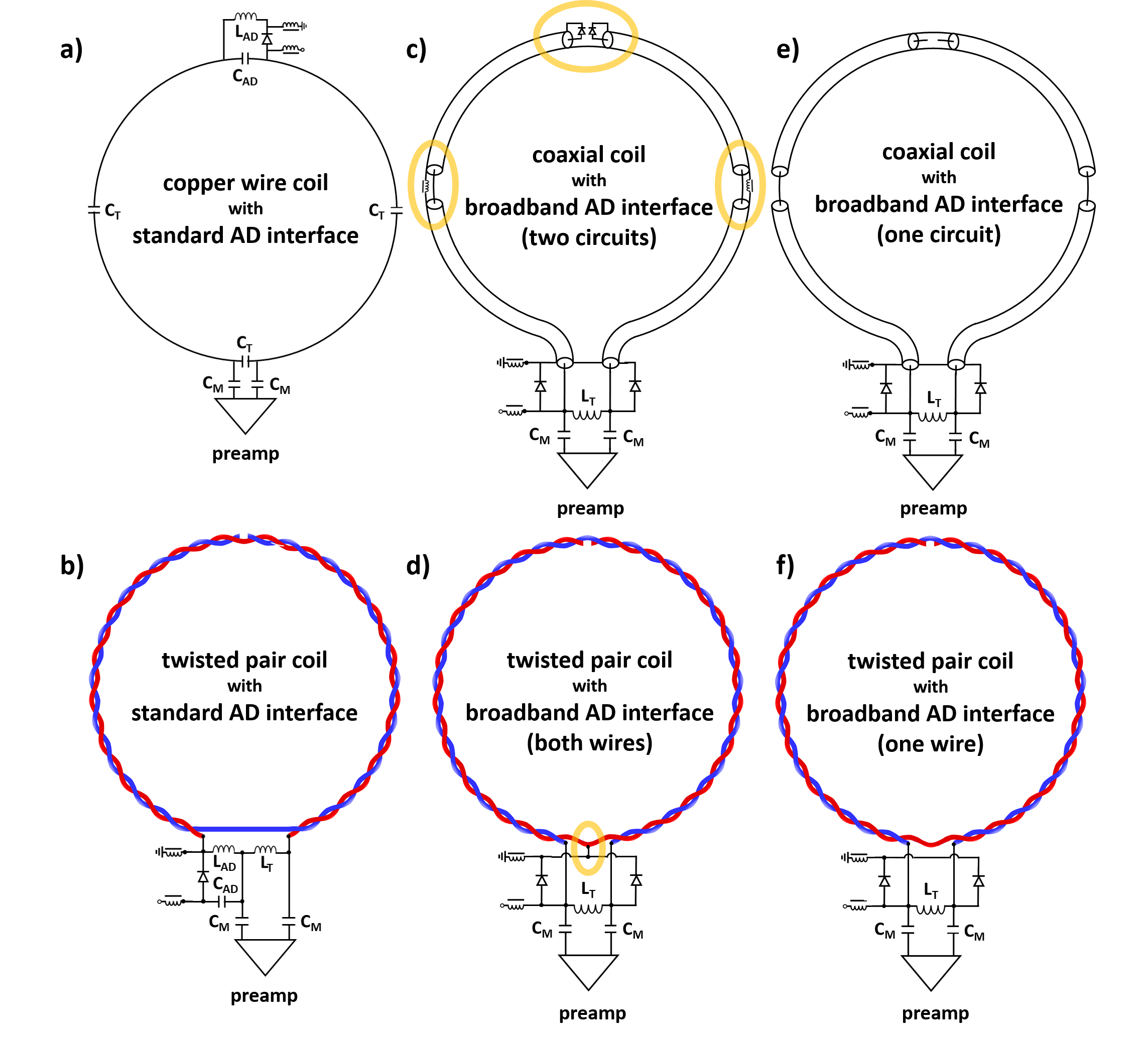
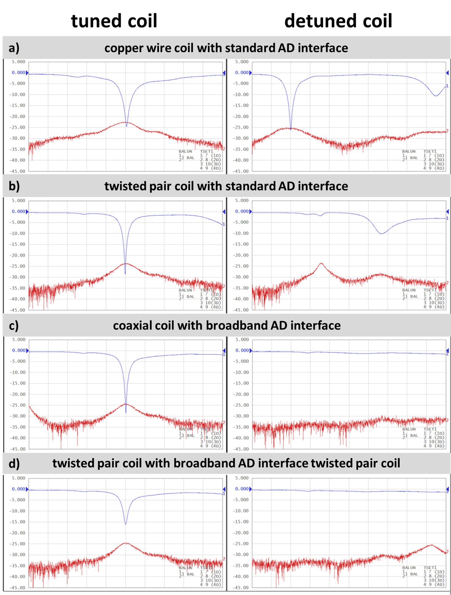
Standard copper wire, coaxial and twisted pair coils were constructed for Rx-only operation at 7 T. They were fabricated with a diameter of 7 cm using flexible conductors in coaxial (29 AWG, Molex, Lisle, IL, USA) and twisted wire pair (22 AWG, RS PRO, Gmuend, Austria) arrangement. The coaxial coil was fabricated with 2 gaps per conductor9, whereas for the twisted pair coil only one gap was necessary to obtain a self-resonance close to the Larmor frequency. The circuit scheme of all tested coils and respective interfacing can be seen in Fig.1. A box phantom (13x16x8 cm3) filled with saline solution and doped with Gadoteric acid was used (σDC=0.2 S/m) for bench and MR measurements.Bench measurements were performed using a vector network analyzer (E5071C, Agilent, Santa Clara, CA, USA). Q-factors in unloaded and loaded configuration were measured without coil interface. The coils’ matching (S11) and the effectiveness of the AD circuit (S21, dual-loop probe10) were determined. Fig.2 illustrates the functioning principle of different AD networks: With a narrow-band “standard AD network” resonance peak splitting can be observed whereas with the “broadband AD network”, the resonant circuit is shortened hence eliminating any residual resonance in a large frequency span.
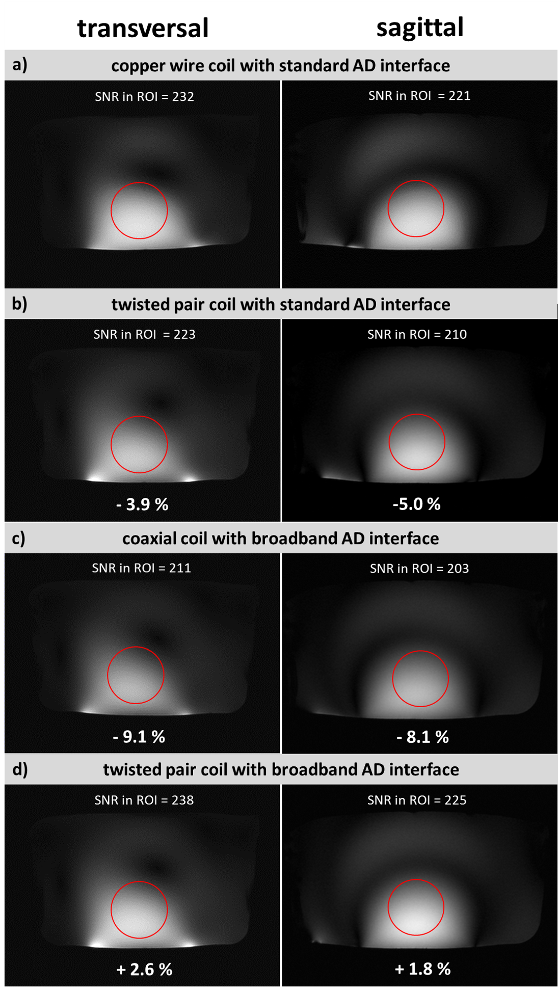
MR measurements were carried out on a 7 T scanner (Magnetom, Siemens Healthineers, Erlangen, Germany) with the Rx coils directly placed on the phantom and connected to a preamplifier (0.5 dB noise figure, 27.2±0.2 dB gain, Siemens Healthineers, Erlangen, Germany). A 24-leg birdcage coil11 (18 cm diameter, 21 cm length) was used for RF transmission. Gradient-echo (GRE) images were acquired in transversal and sagittal orientation. These data were used for SNR estimation in a circular region of interest (ROI). Flip angle (FA) maps12 were obtained using the birdcage in Tx/Rx mode with and without the presence of the Rx coil to test the reliability of the AD. Relative FA differences were calculated in a rectangular ROI close to the coil using MATLAB (The Mathworks, Inc., Natick, USA).
Results and Discussion
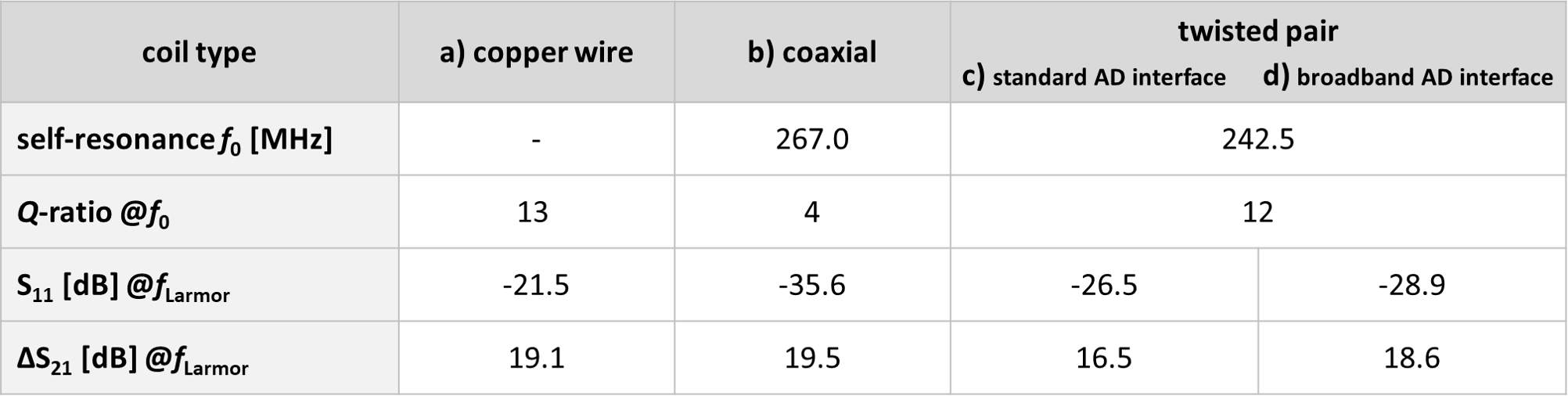
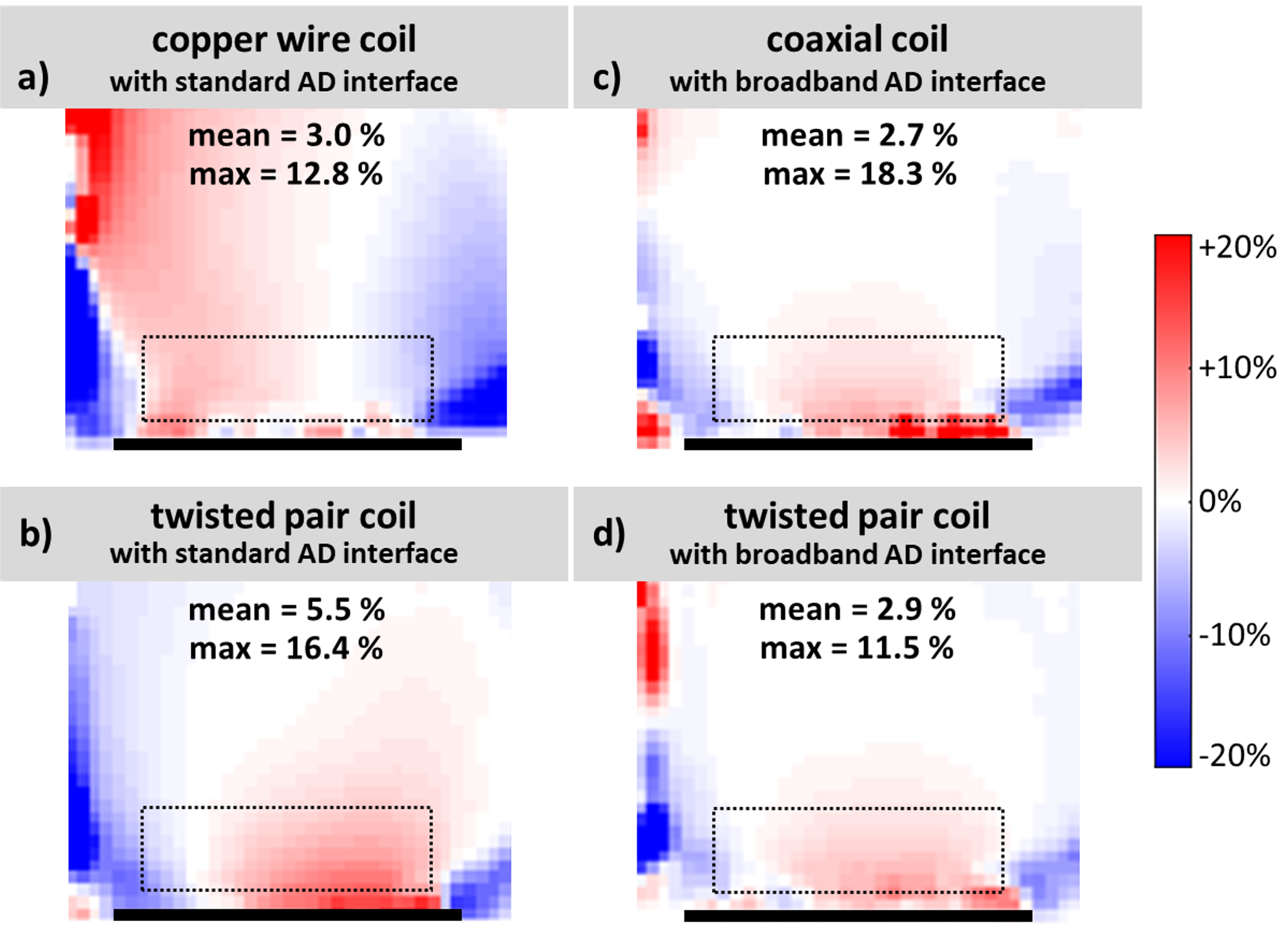
Bench measurement results are given in Tab.1. Acquired FA maps including the mean and maximum FA difference values in a ROI close to the coil are shown in Fig.3. ΔS21 measurements (tuned vs. detuned state) >16.5 dB and a mean FA difference <5.5% evaluated close to the coil demonstrate sufficient decoupling between Rx coils and Tx coil. The highest mean FA difference for the twisted pair coil with standard AD interface could be related to the smaller frequency span of the resonance splitting compared to the copper wire coil (see Fig.2).Transversal and sagittal GRE images including calculated SNR ratios in the circular ROI are depicted in Fig.4. The different Rx coils (a-d) showed very similar performance, with higher SNR for the twisted pair coil using the broadband AD interface (+2.6%/+1.8% in a transversal/sagittal slice) and lower SNR for the coaxial coil (-9.1%/-8.1%) compared to the copper wire coil. The latter might be attributed to the higher amount of components necessary for AD along the coil conductor (second set of PIN-diodes and RF chokes).
For the coaxial coil with AD components only at the coil port (case e in Fig.1), we experienced insufficient detuning in terms of too high relative FA difference (mean=10.0%, maximum=28.8%), as has also been reported for 3 T coils9. With two AD circuits, i.e., PIN diodes at both inner gaps and RF chokes at both outer gaps, the coaxial coil showed good decoupling (Fig.3c).
Additional measurements with a twisted pair coil and modified broadband AD, shorting only the blue wire at the coil port (case f in Fig.1), showed that the bench and MR performance was equal to coil d (therefore coil f data are omitted in the results). This could be exploited to reduce the number of interface components and related losses, i.e. using only one PIN diode for AD in future work.
Conclusion
The successful development of flexible twisted wire pair and coaxial transmission line Rx coils at 7 T was demonstrated. Reliable active detuning mechanisms for twisted pair coils have been implemented. Flexible coaxial and twisted pair coils showed similar SNR performance compared to a standard copper wire coil. The possibility to miniaturize twisted pair coil interfacing could be beneficial for the design of versatile flexible Rx coil arrays at 7 T.Acknowledgements
This project was funded by the Horizon Europe grant, Nr. 101078393, “MRITwins” and Austrian Science Fund (FWF) project Nr. P35305-B. We thank Deniz Celebi and Tim Hebenstreit (both Medical University of Vienna) for their contribution.References
1. Maravilla, J. A., Gopalan, K., Arias, A. C. & Lustig, M. Transmission Line Receiver Coils (TLCs) for MRI. in Proc. Intl. Soc. Mag. Reson. Med. 30 (2022), London, UK, p. 189.
2. Zabel, H. J., Bader, R., Gehrig, J. & Lorenz, W. J. High-quality MR imaging with flexible transmission line resonators. Radiology 165, 857–859 (1987).
3. Zhang, B., Sodickson, D. K. & Cloos, M. A. A high-impedance detector-array glove for magnetic resonance imaging of the hand. Nat Biomed Eng 2, 570–577 (2018).
4. Yang, X., Zheng, T., Wu, Y. & Finnerty, M. Coaxial cable magnetic resonance image (MRI) coils.(2017). US patent US9678180B2.
5. Güler, S., Zhurbenko, V., Zivkovic, I., Boer, V. O. & Petersen, E. T. Second resonance mode ensure intrinsic low coupling between elements on shielded-coaxial-cable coil designs. in Proc. Intl. Soc. Mag. Reson. Med. 30, London, UK, p. 1545.
6. Ruytenberg, T., Webb, A. & Zivkovic, I. Shielded-coaxial-cable coils as receive and transceive array elements for 7T human MRI. Magn. Reson. Med. 83, 1135–1146 (2020).
7. Mollaei, M. S. M., Van Leeuwen, C. C., Raaijmakers, A. J. E. & Simovski, C. R. Analysis of high impedance coils both in transmission and reception regimes. IEEE Access 8, 129754–129762 (2020).
8. Zhang, B. et al. Twenty-four-channel high-impedance glove array for hand and wrist MRI at 3T. Magn. Reson. Med. 87, 2566–2575 (2022).
9. Nohava, L. et al. Flexible Multi-Turn Multi-Gap Coaxial RF Coils: Design Concept and Implementation for Magnetic Resonance Imaging at 3 and 7 Tesla. IEEE Trans. Med. Imaging 40, 1267–1278 (2021).
10. Darrasse, L. & Kassab, G. Quick measurement of NMR‐coil sensitivity with a dual‐loop probe. Rev. Sci. Instrum. 64, 1841–1844 (1993).
11. Raghuraman, S. et al. 12-channel receive array with a volume transmit coil for hand/wrist imaging at 7 T. J. Magn. Reson. Imaging 38, 238–244 (2013).
12. Chung, S., Kim, D., Breton, E. & Axel, L. Rapid B1+ mapping using a preconditioning RF pulse with TurboFLASH readout. Magn. Reson. Med. 64, 439–446 (2010).
Figures