3725
Miniature and flexible Bazooka balun for MRI RF coils1Vanderbilt University Institute of Imaging Science, Vanderbilt University Medical Center, Nashville, TN, United States, 2Department of Radiology and Radiological Sciences, Vanderbilt University Medical Center, Nashville, TN, United States
Synopsis
Keywords: New Devices, New Devices
Flexible receive coil design has been researched on for a long time. However, several challenges is still presenting. One of them is the still bulky and rigid balun. Here we exhibit a novel flexible bazooka balun. It can be built on any coaxial cable and is formed by heat shrinks and braided wires. The flexible balun is smaller than conventional balun in length and size.Introduction
Recently, there has been an increasing trend toward more flexible and lightweight RF coil arrays for MRI [1]–[14]. Flexible coils improve patient comfort and can be formed into desired shapes to match the human anatomy of interest. Although the challenges in building flexible coils have been somehow solved with the numerous methods mentioned above, in practice, it is still an open question to make fully flexible coils since the balun circuits associated with coils are still rigid and bulky. To address this problem, in this work, we proposed a novel miniature and flexible bazooka balun to realize fully flexible RF coils.Methods
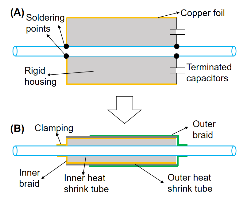
ConceptFigure 1a depicts a standard capacitor-terminated bazooka balun that has been widely used in MRI [15]. To make the bazooka balun to be flexible, we (1) used clamping instead of soldering for the connection joints; (2) replaced the rigid housing with an ultra-flexible silicon rubber tube; (3) replaced the rigid capacitor with a flexible coaxial capacitor made from braids and a flexible dielectric substrate (Figure 1b).
Balun Construction
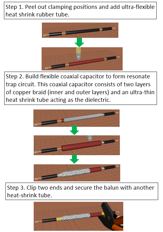
A flexible bazooka balun was built on ultra-flexible coaxial cable (Huber+Suhner G_02232_D) for 7 Tesla. First, the jacket of the cable was peeled out at two positions for the connection with the flexible coaxial capacitor (Figure 2, Step 1). The distance between the two peel-out positions was chosen to match the length of the coaxial capacitor. Prior to adding the coaxial capacitor, we add an ultra-flexible heat shrink silicone rubber tube (McMaster, 2868N11) to the jacket of the coaxial cable between the two peel-out positions. Then a flexible coaxial capacitor was clipped to the cable shield (at peel-out positions) to ensure the balun resonates at the operating Larmor frequency (Figure 2, Step 2). The flexible coaxial capacitor consists of two layers of copper braid (inner and outer layers) and an ultrathin heat shrink (McMaster, 6334K413) tube acting as the dielectric.
Bench test and MR imaging experiment
CMRR of the flexible bazooka balun was measured using the direct measurement method [16, 17]. Each end of the cable’s shield was clipped directly to one port of the VNA. The CMRR was evaluated as the S21 between the two VNA ports. The VNA was calibrated (response calibration) so that S21 = 0 dB corresponded to the case where the same cable with no balun was present. We also built coils with and without baluns and measured their impedance change when their drive cable was touched by hand. As mentioned above, without the balun circuit, the cable would become part of the coil, inducing additional coil loss and impairing the coil efficiency. To further validate the balun’s performance, we measured the transmit efficiency of a single coil without and with the flexible balun and also compared it to the scenario with the conventional cable trap balun.
Results
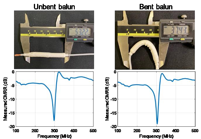
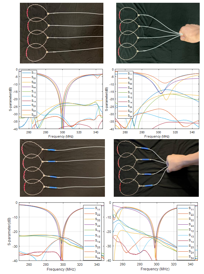
Bench TestThe measured insertion loss (evaluated by S21 in the differential mode) and CMRR of a 298-MHz flexible balun (corresponds to 7 Tesla) are -0.03 dB and -17 dB, as shown in Figure 3. It is also noted that the balun performance was not affected when it was bent. We applied these flexible baluns to a 4-channel flexible coil array and found the difference of measured S-parameters without and with hand effect is ignorable (Figure 4). On the contrary, the return loss and the inter-element coupling of coils without baluns significantly increased when they were held by hands.
Coil Efficiency
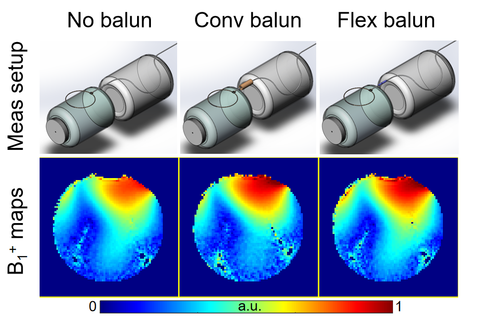
Figure 5 compares transmit efficiency (B1+) maps of single coils without, with rigid cable trap balun, and with the flexible balun. The B1+ efficiency of the coil with flexible balun is almost the same as that of the conventional balun, indicating that the flexible balun exhibits similar suppression ability for the common-mode current. The coil without any balun showed approximately 13% B1+ efficiency loss compared to the coils with a balun.
Conclusion
A novel balun was proposed, numerically analyzed, fabricated, and tested. It does not impair the differential mode signal and exhibits acceptable common-mode suppression capability. It is flexible, miniature, and easy to build, making it suitable for high-density light-weighting RF coils and guidewires in interventional MRI.Acknowledgements
This work was supported by NIH R01 EB031078.References
[1] P. M. Cogswell et al., “Application of Adaptive Image Receive Coil Technology for Whole-Brain Imaging,” American Journal of Roentgenology, vol. 216, no. 2, pp. 552–559, Feb. 2021, doi: 10.2214/AJR.20.22812.
[2] D. Darnell, T.-K. Truong, and A. W. Song, “Recent Advances in Radio-Frequency Coil Technologies: Flexible, Wireless, and Integrated Coil Arrays,” Journal of Magnetic Resonance Imaging, vol. 55, no. 4, pp. 1026–1042, 2022, doi: 10.1002/jmri.27865.
[3] T. W. Deller, N. K. Mathew, S. A. Hurley, C. M. Bobb, and A. B. McMillan, “PET Image Quality Improvement for Simultaneous PET/MRI with a Lightweight MRI Surface Coil,” Radiology, vol. 298, no. 1, pp. 166–172, Jan. 2021, doi: 10.1148/radiol.2020200967.
[4] B. D. Collick et al., “Rapid development of application-specific flexible MRI receive coils,” Phys. Med. Biol., vol. 65, no. 19, p. 19NT01, Sep. 2020, doi: 10.1088/1361-6560/abaffb.
[5] J. M. Vincent and J. V. Rispoli, “Conductive Thread-Based Stretchable and Flexible Radiofrequency Coils for Magnetic Resonance Imaging,” IEEE Transactions on Biomedical Engineering, vol. 67, no. 8, pp. 2187–2193, Aug. 2020, doi: 10.1109/TBME.2019.2956682.
[6] D. Zhang and Y. Rahmat-Samii, “A Novel Flexible Electrotextile 3T MRI RF Coil Array for Carotid Artery Imaging: Design, Characterization, and Prototyping,” IEEE Transactions on Antennas and Propagation, vol. 67, no. 8, pp. 5115–5125, Aug. 2019, doi: 10.1109/TAP.2019.2891700.
[7] S. A. Winkler et al., “Evaluation of a Flexible 12-Channel Screen-printed Pediatric MRI Coil,” Radiology, vol. 291, no. 1, pp. 180–185, Apr. 2019, doi: 10.1148/radiol.2019181883.
[8] R. Frass-Kriegl et al., “Flexible 23-channel coil array for high-resolution magnetic resonance imaging at 3 Tesla,” PLOS ONE, vol. 13, no. 11, p. e0206963, Nov. 2018, doi: 10.1371/journal.pone.0206963.
[9] B. Zhang, D. K. Sodickson, and M. A. Cloos, “A high-impedance detector-array glove for magnetic resonance imaging of the hand,” Nat Biomed Eng, vol. 2, no. 8, pp. 570–577, Aug. 2018, doi: 10.1038/s41551-018-0233-y.
[10] K. P. McGee et al., “Characterization and evaluation of a flexible MRI receive coil array for radiation therapy MR treatment planning using highly decoupled RF circuits,” Phys. Med. Biol., vol. 63, no. 8, p. 08NT02, Apr. 2018, doi: 10.1088/1361-6560/aab691.
[11] X. Yang, T. Zheng, Y. Wu, and M. Finnerty, “Coaxial cable magnetic resonance image (MRI) coil,” US9678180B2, Jun. 13, 2017 Accessed: Nov. 08, 2021. [Online]. Available: https://patents.google.com/patent/US9678180B2/en
[12] J. R. Corea, P. B. Lechene, M. Lustig, and A. C. Arias, “Materials and methods for higher performance screen-printed flexible MRI receive coils,” Magnetic Resonance in Medicine, vol. 78, no. 2, pp. 775–783, 2017, doi: 10.1002/mrm.26399.
[13] J. R. Corea et al., “Screen-printed flexible MRI receive coils,” Nat Commun, vol. 7, no. 1, p. 10839, Mar. 2016, doi: 10.1038/ncomms10839.
[14] R. Kriegl et al., “Novel inductive decoupling technique for flexible transceiver arrays of monolithic transmission line resonators,” Magnetic Resonance in Medicine, vol. 73, no. 4, pp. 1669–1681, 2015, doi: 10.1002/mrm.25260.
[15] Johnson and Jasik, Antenna Engineering Handbook.
[16] M. Wilcox, S. M. Wright and M. P. McDougall, "Multi-tuned cable traps for multinuclear MRI and MRS", IEEE Trans. Biomed. Eng., vol. 67, no. 4, pp. 1221-1228, Apr. 2020.
[17] Zhu, Y., Sappo, C. R., Grissom, W. A., Gore, J. C., & Yan, X. (2022). Dual-tuned Lattice Balun for Multi-nuclear MRI and MRS. IEEE Transactions on Medical Imaging, 41(6), 1420-1430.
Figures