3724
A Rotatable Twisted Solenoid TRASE Phase Gradient Head Coil1University of Alberta, Edmonton, AB, Canada
Synopsis
Keywords: Hybrid & Novel Systems Technology, RF Arrays & Systems, TRASE
TRASE is an MR encoding sequence that utilizes phase gradients of the RF transmit field for k-space encoding. A promising RF coil for TRASE imaging is the twisted solenoid due to its compact design and efficient B1 field. In this work we present the first TRASE head coil, consisting of a geometrically decoupled parallel-transmit (pTx) rotatable twisted solenoid pair. No RF switching hardware is required. The encoding direction of this coil pair is set by rotation angle, allowing for 2D radial k-space acquisitions. This method is compatible with the addition of a static B0 slice selection gradient for multi-slice.
Introduction
Transmit Array Spatial Encoding (TRASE) is an MR encoding sequence utilizing RF phase gradient transmit coils to achieve k-space encoding. Compared to conventional MRI, TRASE can be implemented without switched B0 gradients and is particularly well suited for a low-field, low-cost MRI system1. The most efficient RF coil geometry proposed for TRASE is the twisted solenoid due to its compact, cylindrical design and efficient and uniform B1 field2,3. In previous work, smaller extremity-sized coils were demonstrated2-4. In this study, a pair of head sized RF transmit coils were designed and constructed for the purpose of TRASE head MRI.Methods
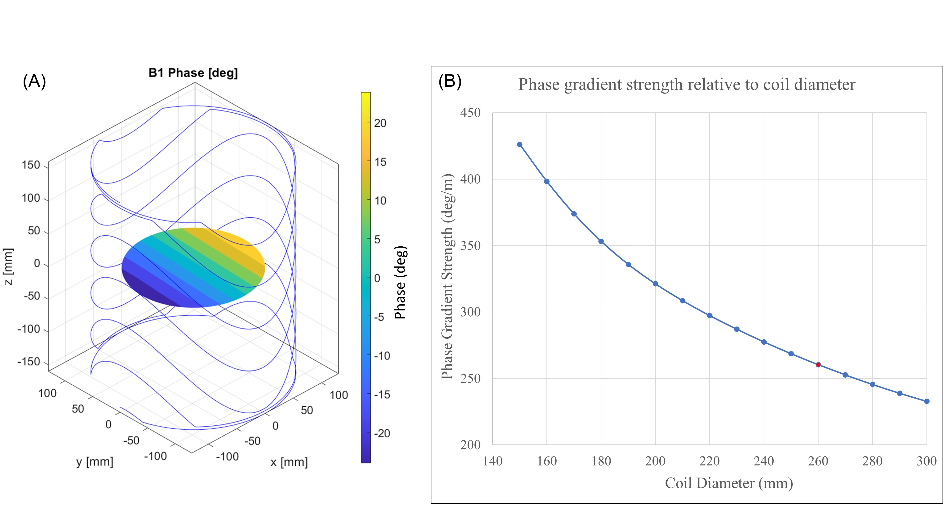
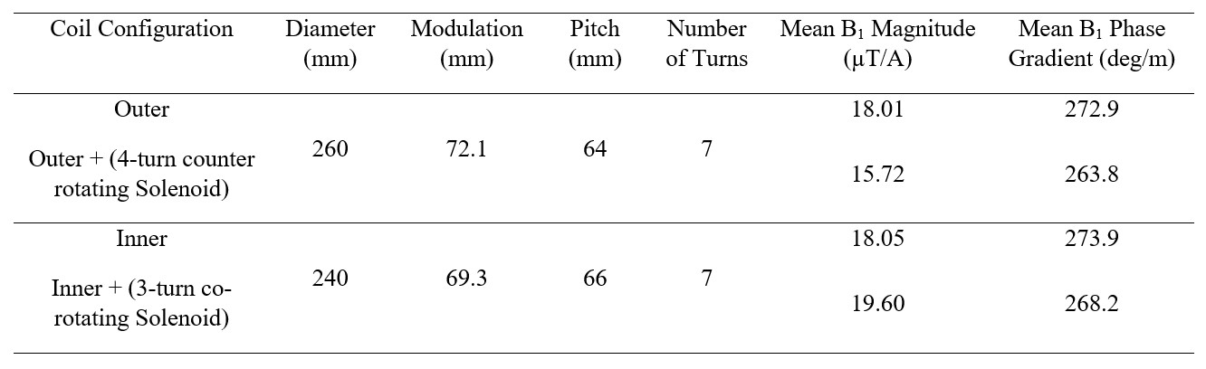
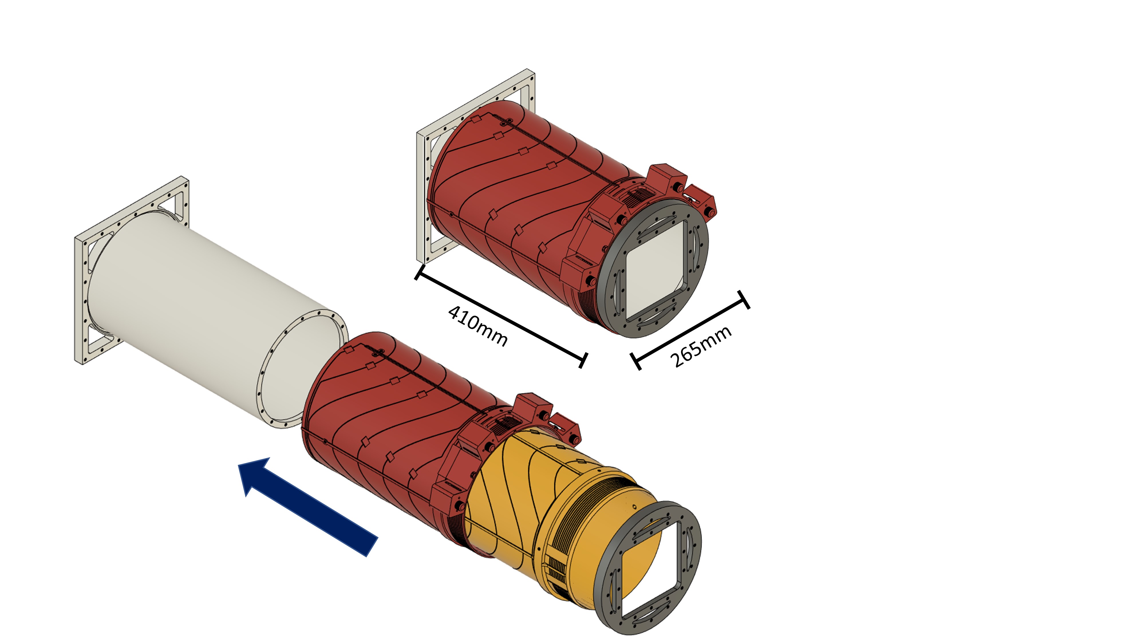
An 8.69MHz twisted solenoid pair for 1D TRASE encoding was constructed for head imaging. Phase gradient strength (and spatial resolution) is inversely related to coil diameter (Fig. 1)2, so the two coils were kept as small as possible. For a brain sized cylindrical target imaging volume of 180mm diameter and 160mm length, two 7-turn coils were designed with diameters of 240mm and 260mm. Both coils were truncated to twice the imaging volume length4, that is, 320mm.The coil geometries were optimized using a parameter search with the MATLAB BSmag package5, with the exact geometries given in Fig. 2. The coils were geometrically decoupled using the two-element solenoid array method3, with a 4-turn counter-rotating and 3-turn co-rotating solenoid added 62mm above the outer and inner coils respectively To mitigate RF propagation phase shift effects, 9 capacitors were used to break up the coil windings into 1.7m segments or smaller (segments < λ/20 at 8.69MHz in free-space)6. The coils were constructed with 18 AWG wire around 3D printed cylindrical PLA formers. The inner coil slides directly into the outer coil and is affixed by nylon screws, with the assembly having an outer diameter of 265mm and length of 410mm. A 230mm inner diameter bore tube was 3D printed, on which the coil pair is freely rotatable to set the encoding direction2.
Results
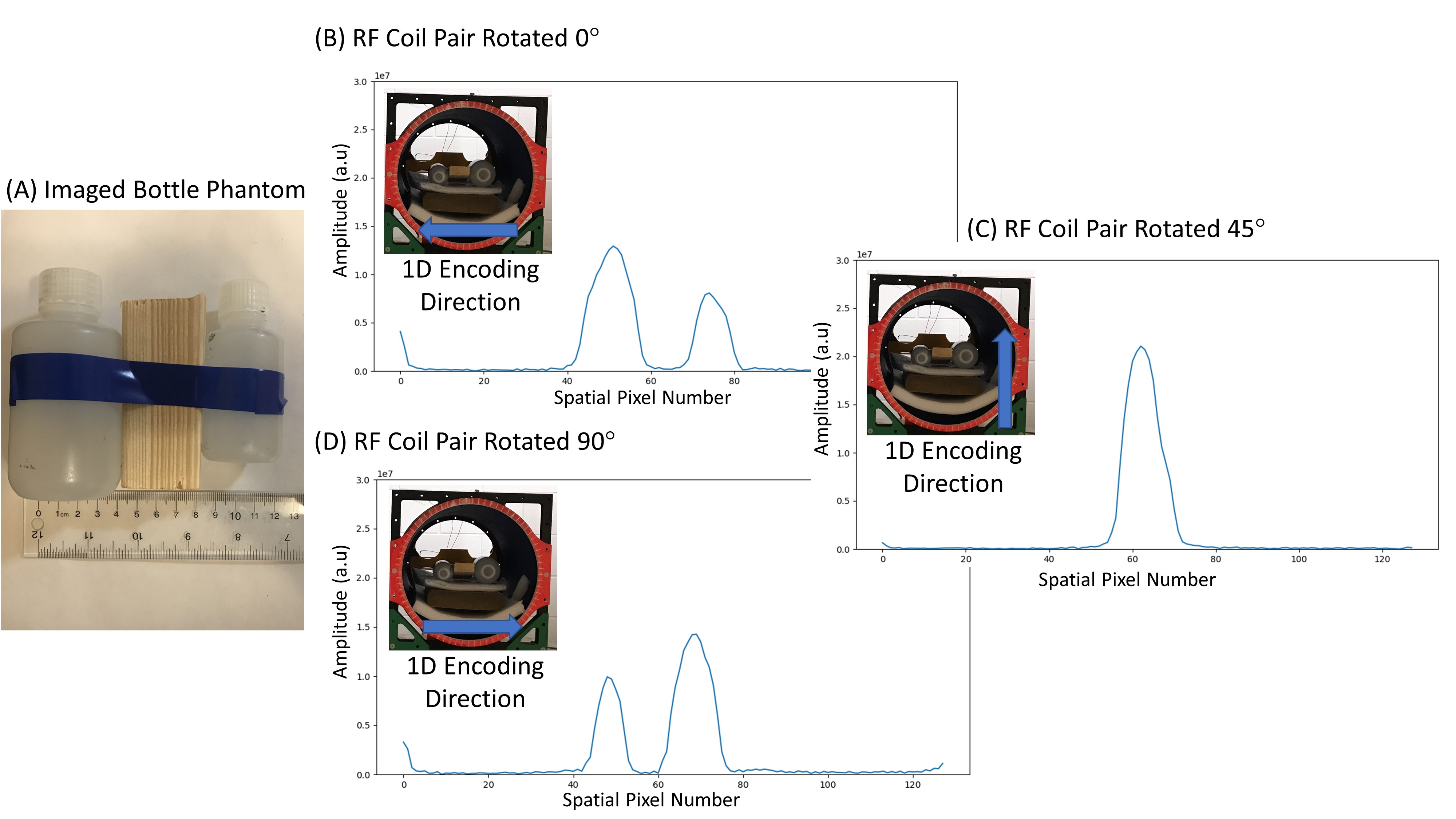
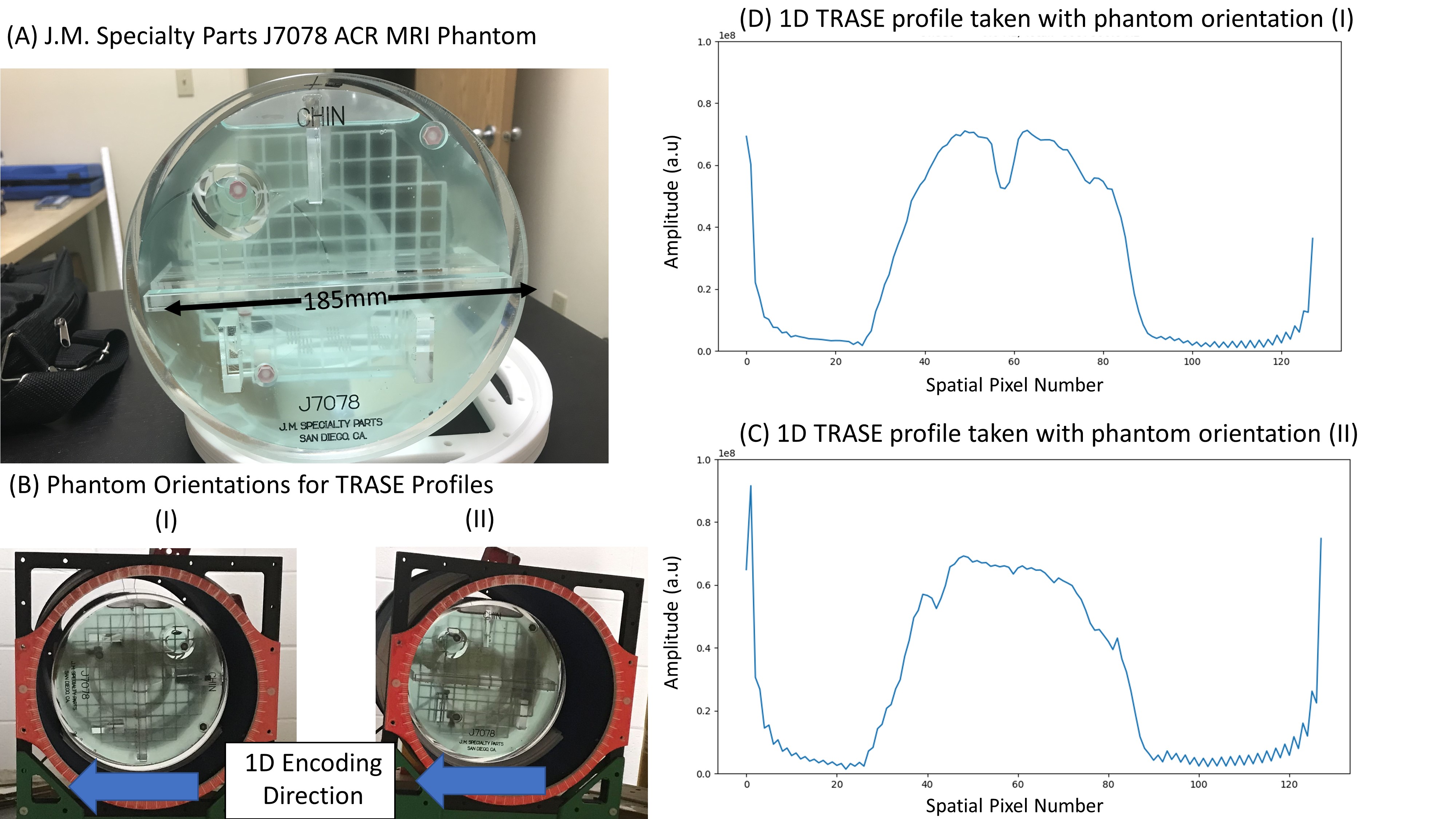
Two bottle phantoms 38mm and 48mm in diameter and 60mm and 75mm in length respectively were separated by 35mm and filled with tap water for imaging. At 8.69MHz the S-parameters were: S11 (outer) = -27.6dB, S22 (inner) = -25.4dB, S12 (coupling) = -24.3dB. Three 1D TRASE profiles were acquired for coil rotations: 0°, 45°, and 90°, corresponding to 0°, 90° and 180° encoding directions2.To illustrate encoding over a head sized region, two orthogonal 1D TRASE projections were acquired through a 185mm i.d. 150mm long ACR phantom (J.M. Specialty Parts J7078).
Experiments were performed on a uniform whole body vertical B0 8.69MHz magnet with our custom pTx DNMR console and RF amplifier system7,8. The 1D TRASE sequence used a 400us hard pulse for excitation and refocusing, echo spacing of 1500µs, repetition time of 3000ms, echo train length (ETL) of 128, and 4 averages. The measured peak powers for the 400µs refocusing pulse for the outer and inner coils respectively were 53.6W and 25.1W (two bottle phantom) and 133.8W and 40.5W (head ACR phantom). The power for the outer coil was higher than expected based on the coil’s sensitivity (Fig. 2), and will require further investigation.
Discussion
The 1D profiles in Fig. 4. show the expected profiles of the two-bottle phantom in the three encoding directions. This capability to set encoding direction by coil orientation will allow a 2D radial MRI acquisition mode. Advantageously, 2D encoding by RF coil rotation (with static patient and magnet) can be implemented with minimal technology, while avoiding the complexities and costs of additional RF Tx channels and switching subsystems2,3.The 1D profiles from the J7078 ACR head phantom are shown in Fig. 5. The phantom itself is large with many points of interest and was imaged without a slice selection gradient. Of note is the influence of the hollow rectangular region in the center of the phantom. In Fig. 5C this hollow region is perpendicular to the encoding direction and causes a dip in the middle of the profile. Conversely, when this hollow region is parallel to the encoding direction the dip in the profile is not visualized (Fig. 5D).
Over the imaging volume the coil pair have a combined mean phase gradient strength of 532deg/m. This corresponds to a FOV of 338mm and a 1D pixel separation of 2.64mm for an ETL of 1281. Various strategies are available to increase spatial resolution, including shorter sequence timings (reducing T2 k-space filtering), and accelerated and sparse k-space sampling strategies. The relatively “high” low-field used in this study (~200mT) also serves to validate the coil design for lower field applications (e.g., Halbach magnets), because lower frequency operation allows more coil turns and requires lower RF power.
Conclusion
1D TRASE RF-encoded profiles from a 185mm diameter head FOV phantom were demonstrated, using a rotatable two-channel pTx coil system, with transverse encoding axis set by rotation angle. The combination of coil rotation and a static axial B0 gradient, will allow the implementation of 2DFT multi-slice head imaging.Acknowledgements
C.S acknowledges Dr. Gordon Sarty, Dr. Pallavi Bohidar, and Dr. Slava Volotovsky for their scientific discussions. The authors would also acknowledge the funding sources from Natural Sciences and Engineering Research Council of Canada, Grants Numbers: RGPIN-2016-05183 and RGPIN-2020-04414.
References
1. Sharp JC, King SB. MRI using radiofrequency magnetic field phase gradients. Magn Reson Med. 2010;63(1):151–161. https://doi.org/10.1002/mrm.22188
2. Sun H, Yong S, Sharp JC. The twisted solenoid RF phase gradient transmit coil for TRASE imaging. J Magn Reson. 2019;299:135–150. https://doi.org/10.1016/j.jmr.2018.12.015
3. Sun H, AlZubaidi A, Purchase A, Sharp JC. A geometrically decoupled, twisted solenoid single-axis gradient coil set for TRASE. Magn Reson Med. 2020;83(4):1484–1498. https://doi.org/10.1002/mrm.28003
4. Sedlock CJ, Purchase AR, Tomanek B, and Sharp JC. A Truncated Twisted Solenoid RF Phase Gradient Transmit Coil for TRASE MRI. In Proceedings of ISMRM; 2022; London, England. Abstract 6513.
5. Queval L, Bsmag toolbox user manual, Tech. report, Dept. Elect. Eng., University of Applied Sciences Düsseldorf, Germany, April 2015. Available from: http://www.lqueval.com
6. Mispelter J, Lupu M, Briguet A. NMR Probeheads for Biophysical and Biomedical Experiments: Theoretical Principles and Practical Guidelines. 2nd ed. Imperial College Press; 2015. https://doi.org/10.1142/p759
7. Sharp JC, Purchase AR, Sedlock CJ, and Tomanek B. A Parallel-Transmit Halbach Magnet TRASE MRI System. In Proceedings of ISMRM; 2022; London, England. Abstract 5670.
8. Purchase AR, Palasz T, Sun H, Sharp JC, Tomanek B. A high duty‐cycle, multi‐channel, power amplifier for high‐resolution radiofrequency encoded magnetic resonance imaging. Magn Reson Mater Phys Biol Med. 2019;32:679–692. https://doi.org/10.1007/s10334-019-00763-1
Figures