3723
Analysis of the interactions between a TMS coil and a standard receive-only RF loop for MR imaging at 3T
Lucia Navarro de Lara1,2, Qinglei Meng1,2, Jason P Stockmann1,2, Sergey Makarov1,2,3, Mohammad Daneshzand1,2, Larry L Wald1,2, and Aapo Nummenmaa1,2
1Martinos Center for Biomedical Imaging/MGH, Charlestown, MA, United States, 2Harvard Medical School, Boston, MA, United States, 3Worcester Polytechnic Institute, Worcester, MA, United States
1Martinos Center for Biomedical Imaging/MGH, Charlestown, MA, United States, 2Harvard Medical School, Boston, MA, United States, 3Worcester Polytechnic Institute, Worcester, MA, United States
Synopsis
Keywords: Hybrid & Novel Systems Technology, Hybrid & Novel Systems Technology, TMS/fMRI
Specialized MR hardware is needed to combine non-invasive brain stimulation methods (e.g., TMS) and concurrent acquisition of functional MR images. Such integrated hardware systems enable studying causal relationships between the cortical and subcortical nodes of large-scale brain networks. For best possible imaging performance, all interactions of the stimulation coils on the transmit, encoding and receive system of the MR system should be analyzed on detail. The presented approach enables quantitatively assessing the influence of the TMS coils on MR imaging receive hardware. Understanding the effects could lead to improved design strategies for integrated TMS/MRI systems.Introduction
The combination of non-invasive brain stimulation like transcranial Magnetic Stimulation (TMS) with fMRI offers the unique benefits of studying the causal relationships between the cortical and subcortical nodes of large-scale brain networks (1). Multichannel Transcranial Magnetic Stimulation (mTMS) is an emerging technology for non-invasive stimulation of the human brain with the capability of shifting of the TMS ‘hot spot’ electronically without any mechanical movement. This is achieved by computationally determining the current amplitudes to be passed to each of the coil elements to synthesize a desired target field pattern (2). This characteristic of the mTMS has the potential to dramatically ease the combination of TMS and fMRI by solving an important challenge which is the TMS coil positioning in the bore and the consistency of the stimulation target during the session.For this reason, a whole head 28-channel RF coil array was designed and constructed to be integrated with the first 3-axis-TMS multichannel system (3) (see Fig.1). The 16 RF coil elements were constructed on the former holding the TMS and tuned and matched to the Larmor frequency with the TMS elements present. Although strong detuning effects were noted (4), a detailed analysis of how the TMS coils changes the sensitivity of the RF loops was not previously performed. To fill this gap, we analyze this effect using simulations validated with bench measurements.
Methods
First, a combination of electromagnetic simulations (EM) and lumped circuit co-simulations were realized using HFFS (Ansys, Canonsburg, PA, USA) of a 7 cm diameter RF loop 10 mm from a homogeneous realistic head phantom (ξ’=79 and conductivity of σ=0.69 Siemens/m) as a baseline (see Fig. 2/First column). Then, we placed a circular “dummy” TMS coil inside the RF loop (see Fig.2/Second column) at three positions relative to the phantom (0mm, 5mm and 17mm). To facilitate comparison with measurements, the simulated coil was tuned and matched to achieve similar values to those measured at the bench for each set up (due to the detuning effect produced by the TMS on the RF coil; see, Table 1). For all simulations, we exported the magnitude of on a Cartesian grid for further processing using in-house MATLAB scripts. To validate the results, we measured the coil’s sensitivity pattern using 2D GRE images (2mm in-plane resolution, SL= 3mm, 45 slices, MA 96x110 TE=2.76ms, TR=889ms, FA=90°) and flip angle maps (2mm in-plane resolution, SL = 3mm, 45 slices, TE=2.24ms TR=19720ms, MA=96x96, FA=8°) on the bullet phantom shown in Fig. 3. In all measurements we used the same transmit voltage to calculate normalized SNR maps for the different experimental settings, calculating the optimal coil combination (4) and normalizing the maps with the sin(FA) to remove transmit effects produced by the TMS unit (5). Results in both cases are presented as percentage gain or loss with respect to that with the TMS coil absent (same for the B-1):SNR % = 100*(SNRTMS -SNRnoTMS)/SNRnoTMS
Results
Fig.2 and Fig.3 show the results of the simulations and measurements. The TMS coil introduced a well-defined change in the sensitivity pattern in the measurement which is reproduced in the simulation. The effects decrease as the TMS coil is moved away from the phantom and is minimal at the 17 mm coil-to-scalp distance. Fig.4 shows the course of the sensitivity changes along the dash line depicted in Fig.2/Fig.3 for the simulation and measurement, respectively.Discussion
The loss in the RF coil sensitivity observed in simulations and measurements follows a very similar spatial pattern. We also observed that increasing the distance between the TMS coil and the head/phantom decreases the effects on the sensitivity of the RF coil in both cases. The effect observed can likely be explained by eddy currents induced on the “dummy” TMS coil by the MR signal, which appear as losses and shielding effects in the receive circuit. We observed a very similar spatial pattern in both simulation and measurement. However, we also observed some quantitative differences in the sensitivity losses between the simulations and the measurements which may be explained by a mismatch of the material parameters and differences in the coil model used in the simulation (e.g., the simulation coil was only tuned and match while the receive loop has additional circuit elements.) Nevertheless, the profiles analyzed show a high degree of similarity of the sensitivity loss change over depth between the simulations and measurements.Conclusion
We presented a quantitative approach for obtaining mechanistic insights on how TMS coils may interact with the MR imaging hardware. This could facilitate further design efforts to minimize the observed effects.Acknowledgements
This work was funded by NIH R01MH111829, NIH R01EB028797, NIH P41EB030006 and NIH K99EB032749. We also want to thank Jonathan Polimeni for sharing his scripts for the calculation of SNR maps.References
(1) Siebner H et al, Brain Stim (2009),58-50,2(2)
(2) Ruohonen J, Ilmoniemi R, Med and Biol. Eng. Comput. (1998), 297-2301, 36(3)
(3) Navarro de Lara et al, Proceedings of the ISMRM 2022, London UK
(4) Kellman P and McVeigh E, MRM (2005), 1439-47, 54(6)
(5) Navarro de Lara et al., MRM (2020), 1061-1075, 84(2)
Figures
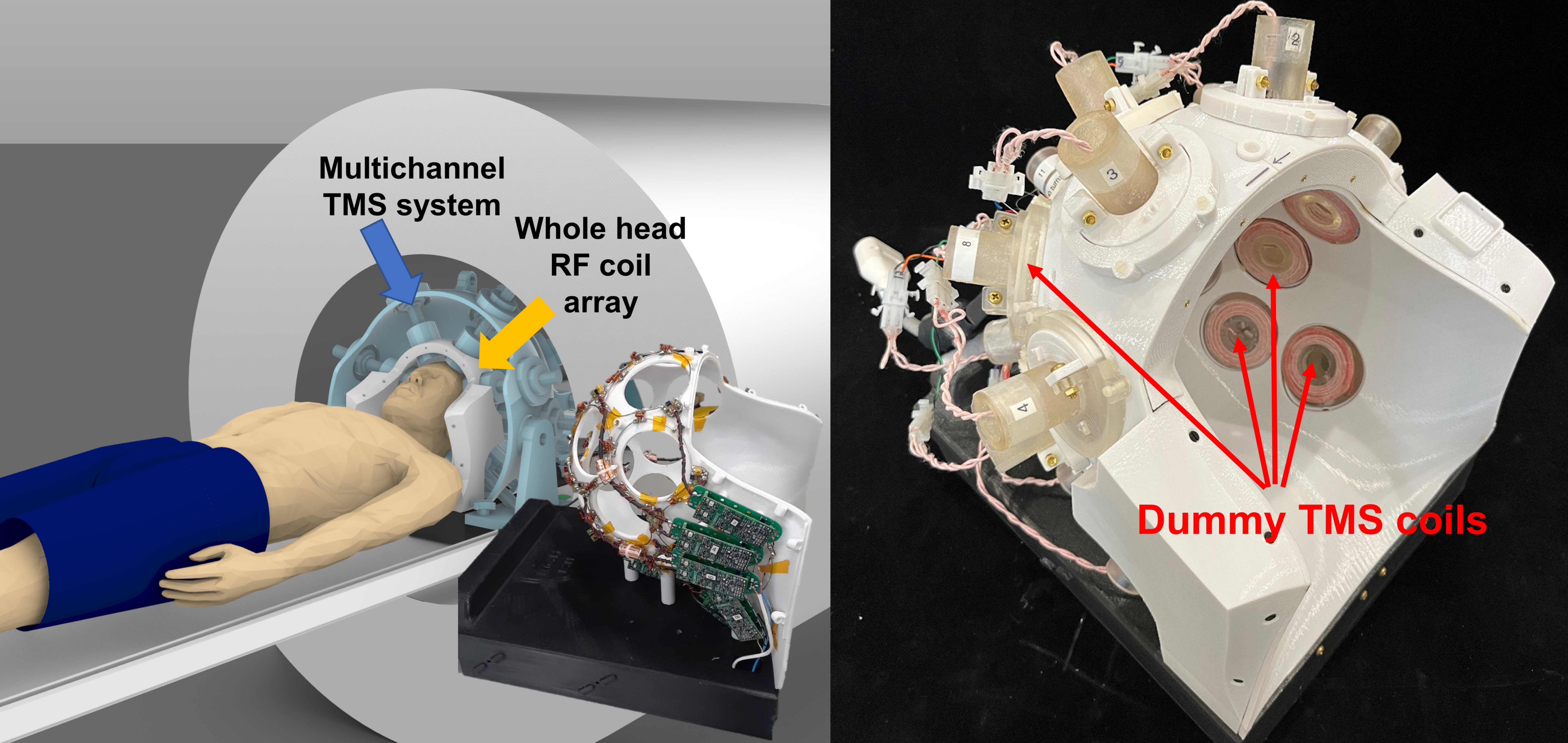
Figure 1. Left) Overview of the multichannel TMS system integrated with a whole-head receive-only
RF coil (TMSMR 28 channel). Detail picture of the constructed coil in the
center image. Right) Constructed TMSMR 28
channel head coil loaded with “dummy”
TMS coils to emulate the final mTMS system.
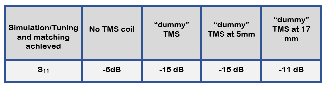
Table 1. Values used for tuning and matching the RF loop in
the simulation to mimic the experimental set up using the TMSMR 28 channel.
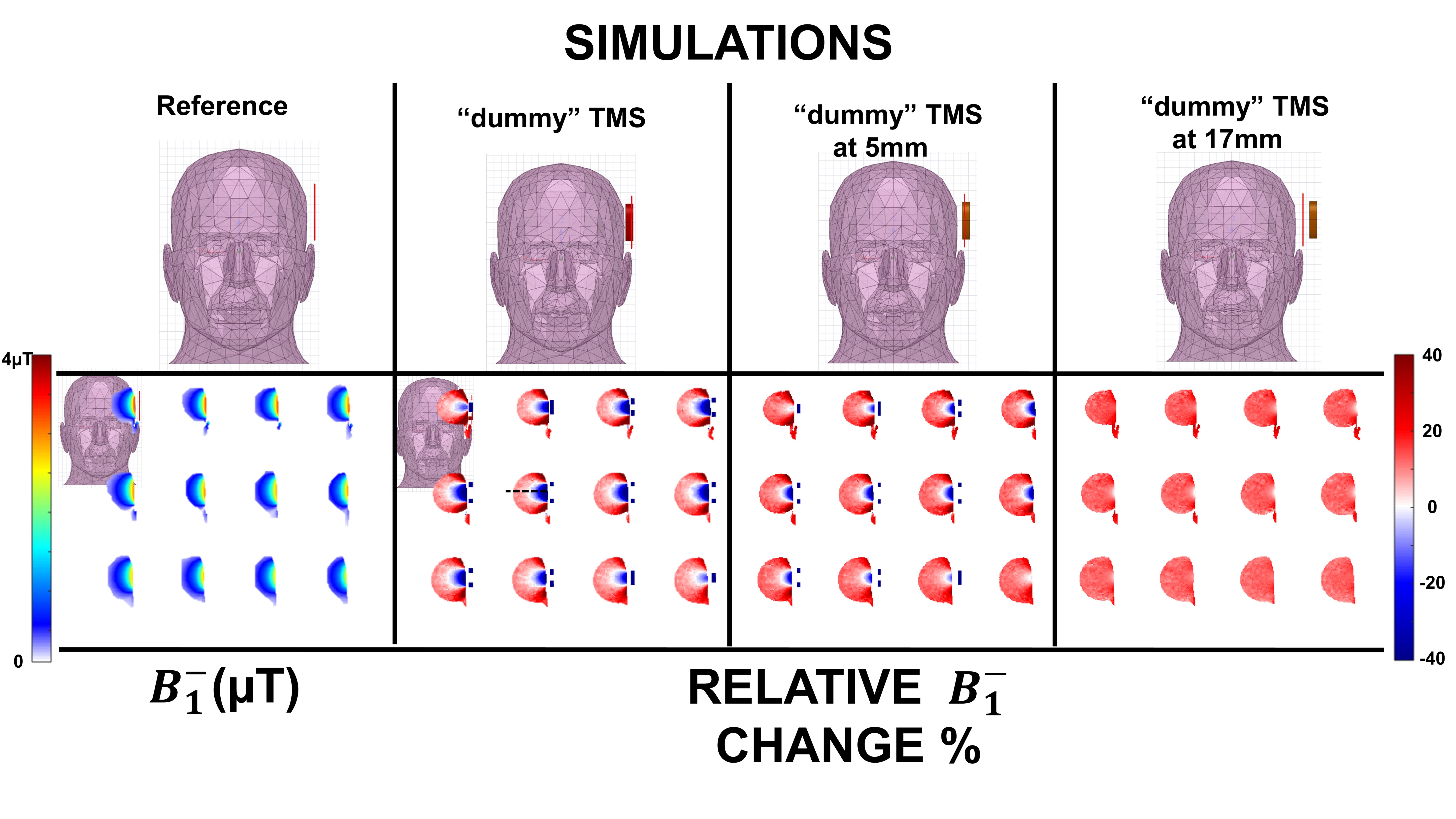
Figure 2. Simulation results of
the “dummy” TMS coil effects on the RF loop’s sensitivity. Top)
Diagrams of the set ups for each case simulated Bottom) Results of
the simulations. The results are shown as relative percentage either loss or
gain in with respect to the reference case depicted on
the top left of the figure. Under the reference
simulation, the calculated B-1 is
shown.
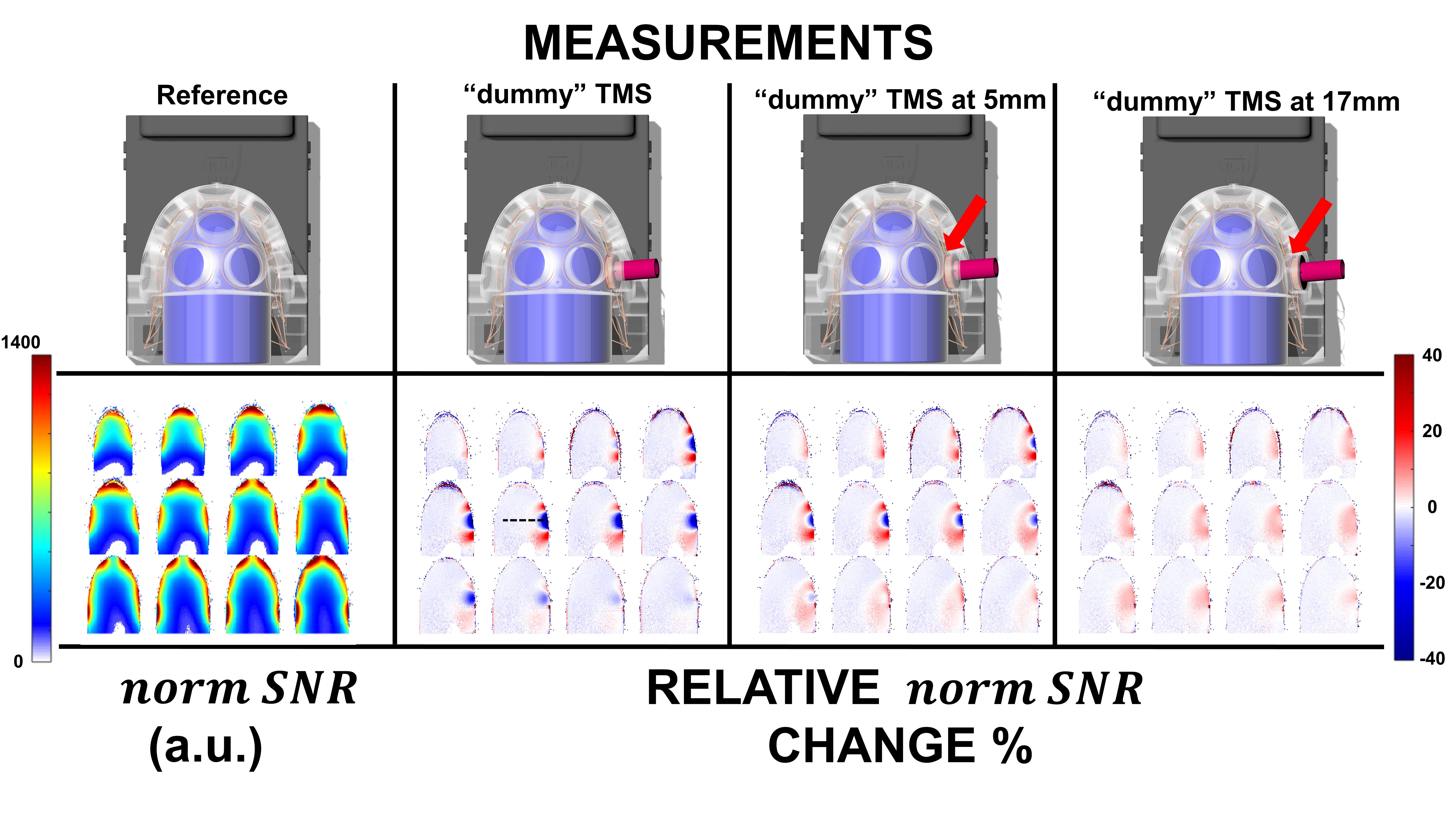
Figure 3. Measurement results
of the “dummy” TMS coil effects on the RF loop’s sensitivity. Top)
Set ups for each
case measured. Bottom) Results of the measurements performed using the
bullet phantom and using the TMSMR 28 channel. The results are shown as
percentage either loss or gain of the calculated normalized SNR with respect to
the reference case depicted on the left of the figure. Under the reference measurement,
the calculated normalized SNR is shown.
Figure 4. Top) Phantoms used for the simulations and the measurements with the
dimensions. Bottom) Plot of the course of the sensitivity (either B1- or SNR) for both
cases, simulations and measurement along the black dash line shown in Fig.2/Fig3.
DOI: https://doi.org/10.58530/2023/3723