3300
High Resolution Intracranial MR Angiography at 3T and 7T using a Deep Learning based Image Reconstruction1GE Healthcare, Tokyo, Japan, 2GE Healthcare, Waukesha, WI, United States, 3GE Healthcare, Menlo Park, CA, United States, 4GE Healthcare, Calagary, AB, Canada, 5University of Iowa, Iowa City, IA, United States, 6Hirosaki University Graduate School of Medicine, Aomori, Japan
Synopsis
Keywords: Blood vessels, Machine Learning/Artificial Intelligence, 7T MRI
Ultra-high-field MRA shows the promise to improve visualize the microvasculature and become an important investigation tool for research. However, increasing the consistency in image quality and reliability of small vessel visualization is necessary to demonstrate useful MR applications in clinical practice. We developed a deep learning-based reconstruction method to provide reduced noise and enhanced spatial resolution. The technique was evaluated by applying it to 3DTOF MRA data at 3T and 7T, demonstrating improved small vessel depiction.
Introduction
Cerebral small vessel disease (SVD) has recently attracted attention in the fields of stroke and dementia1. Non-contrast and non-invasive 3DTOF MRA has become a potentially useful tool for small vessel imaging in 3T and ultra-high field (UHF) 7T MRI2. However, higher detection sensitivity to clearly and reliably visualize small vessels is needed for clinical translation. Deep learning reconstruction (DL Recon)3 provides an opportunity for increased SNR, reduced artifacts, and enhanced resolution. In this work, we explore the feasibility of leveraging DL Recon and perform a phantom and volunteer study on 3T and 7T MRI to provide improved small vessel delineation.Methods
The 3D DL Recon used in our study (AIR Recon DL, GE Healthcare)3 is a deep convolutional residual encoder network trained to reconstruct images from MR data with reduced noise, reduced Gibbs ringing, and enhanced resolution. The convolutional network is embedded in the image reconstruction, operating on raw complex image volumes.To evaluate basic performance characteristics of the DL Recon in 3DTOF MRA, a spatial resolution phantom of pin grid array with a 2mm distance between pin to pin having a diameter of 1mm was used. Scan protocols with different spatial resolutions of 0.6x0.6x0.8 and 0.6x0.6x1.2 mm3 were used on a 3T scanner. The acquired phantom images and its profile of pins were examined applying the DL Recon on and off for comparison. To evaluate image quality of vessel depictions on both 3T and 7T MRI, healthy volunteers were recruited. Reconstructed images with DL Recon on and off were compared.
GE 3T SIGNA Premier MRI scanner was used at Hirosaki University under IRB approval. A volunteer was scanned with a 48 channel Head coil (GE Healthcare). 3DTOF MRA was performed for targeting the Perforating artery in the following protocols: TR/TE: 25/2.4 ms, receiver bandwidth: 50kHz, FOV: 16x16 cm, slice thickness: 0.4mm, number of slabs: 1, no parallel imaging, spatial resolution: 0.5x0.5x0.4mm3, scan time: 11:48.
GE 7T SIGNA MRI scanner was used at the University of Iowa following IRB approval. A volunteer was scanned with a 32-channel receive coil and a high-performance gradient (G=100mT/m and G=200T/m/s). 3DTOF were performed in the following protocols: TR/TE: 23/2.6 ms, receiver bandwidth: 62.5kHz, FOV: 20x16.2 cm, slice thickness: 0.6mm, number of slabs: 3, MT pulse on, Fat saturation pulse on, ARC parallel imaging factor: 2, spatial resolution: 0.4x0.4x0.6mm3, scan time: 11:56.
Results
Figure 1 shows that the DL Recon image was visually sharper and has higher image contrast between signal intensity and background than conventional reconstruction. The pin structure profile curve of the DL Recon image plotted sharper peak and lower noise floor than that of the DL Recon off image.Figure 2 shows representative MIP images of the Perforating artery on 3T. For large vessel visualization, MIP images with the DL Recon on and off have comparable image quality, but the DL Recon image shows better small vessel delineation of the Perforating artery.
Figure 3 shows representative MIP images of the Perforating artery on 7T. The DL Recon on image provided sharper and lower background signal than the DL Recon off image. The profile plot along the yellow line on the MIP image provides detailed information about the better visualization of the DL Recon MIP.
Figure 4 shows representative 7T DL reconstructed full MIP MRA image.
Discussions and conclusion
The DL Reconstructed MRA images improved the delineation of small vasculature with increased sharpness and reduced background signal on both 3T and 7T MRI, showing a promising technique for increasing the success rate of small vessel visualization. The benefit of increased image sharpness can be translated to accelerated scan times by reducing the acquisition matrix sizes because the primary benefit of the DL Recon would be the denoising effect providing low noise floor on images for small vessel depiction as seen in this study. Additionally, as the introduction of the DL Recon overcomes relatively long scan times, there is scope for further optimization of established MRA protocols at 7T and for SAR reduction by adjustment of TR, FA, acquisition matrix and preparation pulses.Acknowledgements
No acknowledgement found.References
1. Wardlaw JM, Smith C, Dichgans M. Small vessel disease: mechanisms and clinical implications. Lancet Neurol. 2019 Jul;18(7):684-696. doi: 10.1016/S1474-4422(19)30079-1.
2. Park CA, Kang CK, Kim YB, Cho ZH. Advances in MR angiography with 7T MRI: From microvascular imaging to functional angiography. Neuroimage. 2018 Mar;168:269-278.
3. Lebel RM. Performance characterization of a novel deep learning-based MR image reconstruction pipeline. 2020. arXiv preprint, arXiv:2008.06559.
Figures
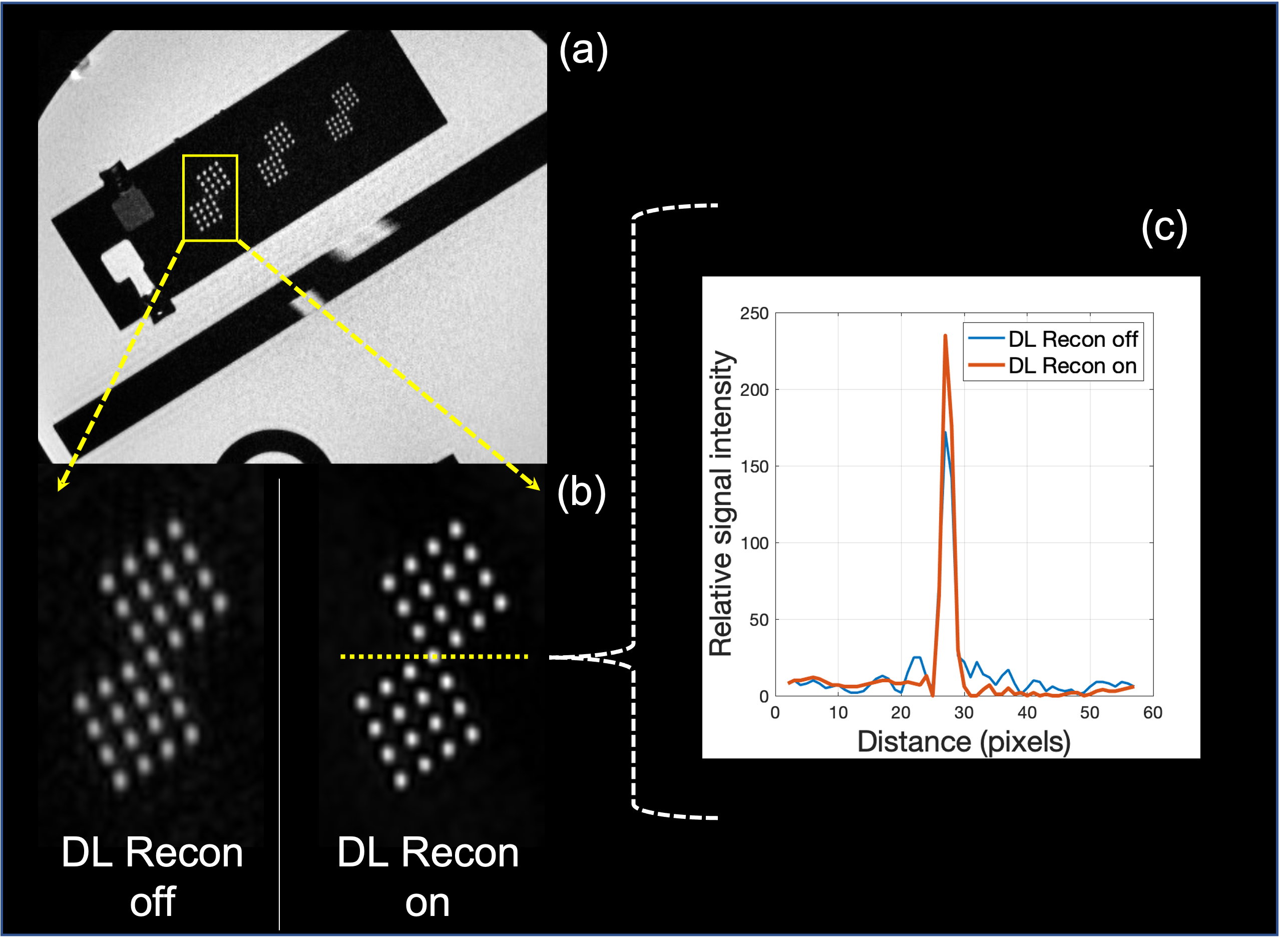
Figure.1. A resolution phantom was scanned to evaluate characteristics of DL Recon with 3DTOF. (a) The resolution phantom with pin array structures. (b) The reconstructed images of DL Recon on in Red and off in Blue. (c) The profile curve along the yellow dotted line in (b).
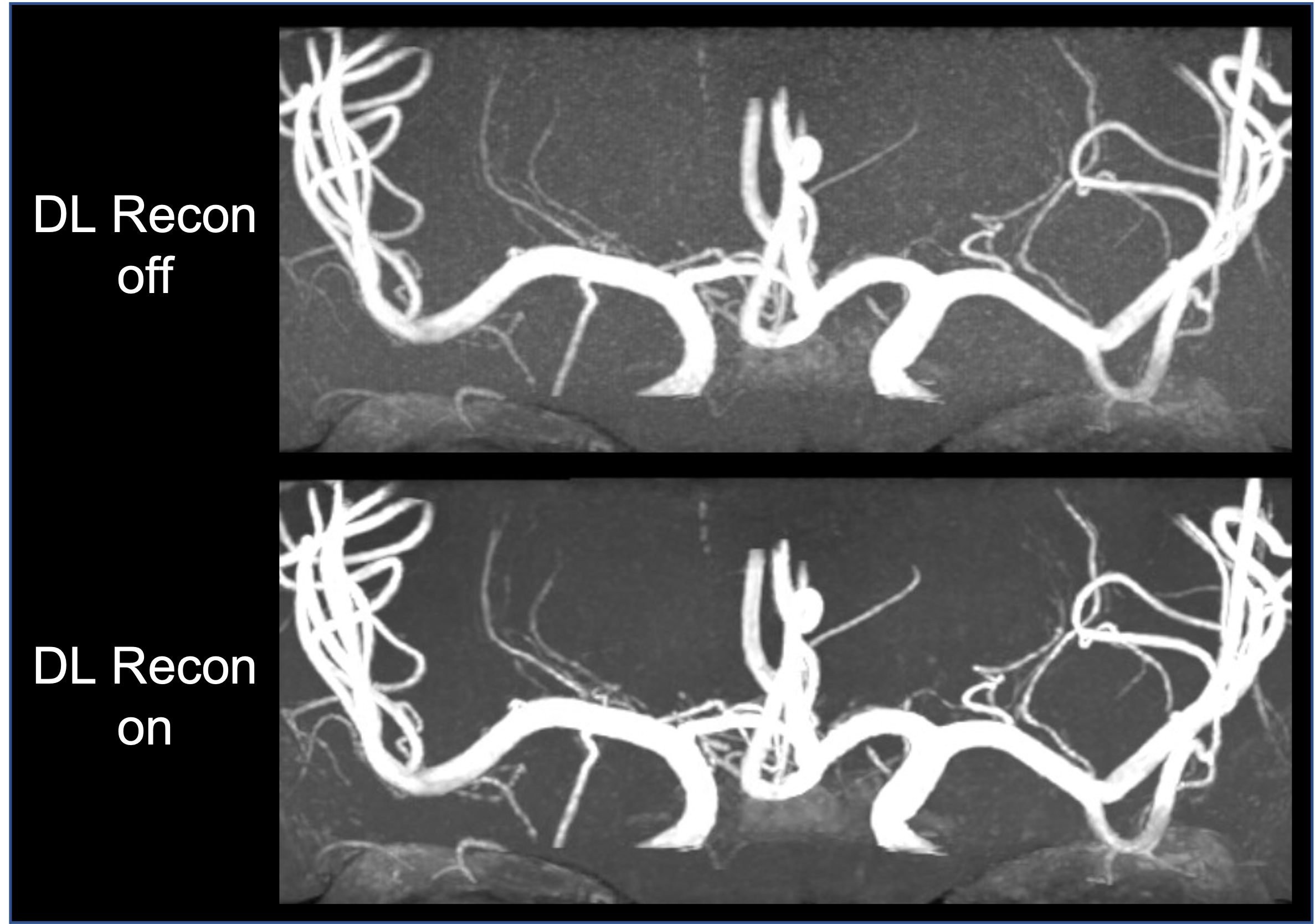
Figure.2. Representative Perforating artery images on 3T. The upper image: 3D TOF MIP image with no DL Recon. The lower image: 3D TOF MIP image with DL Recon on. The same window level and width were used.
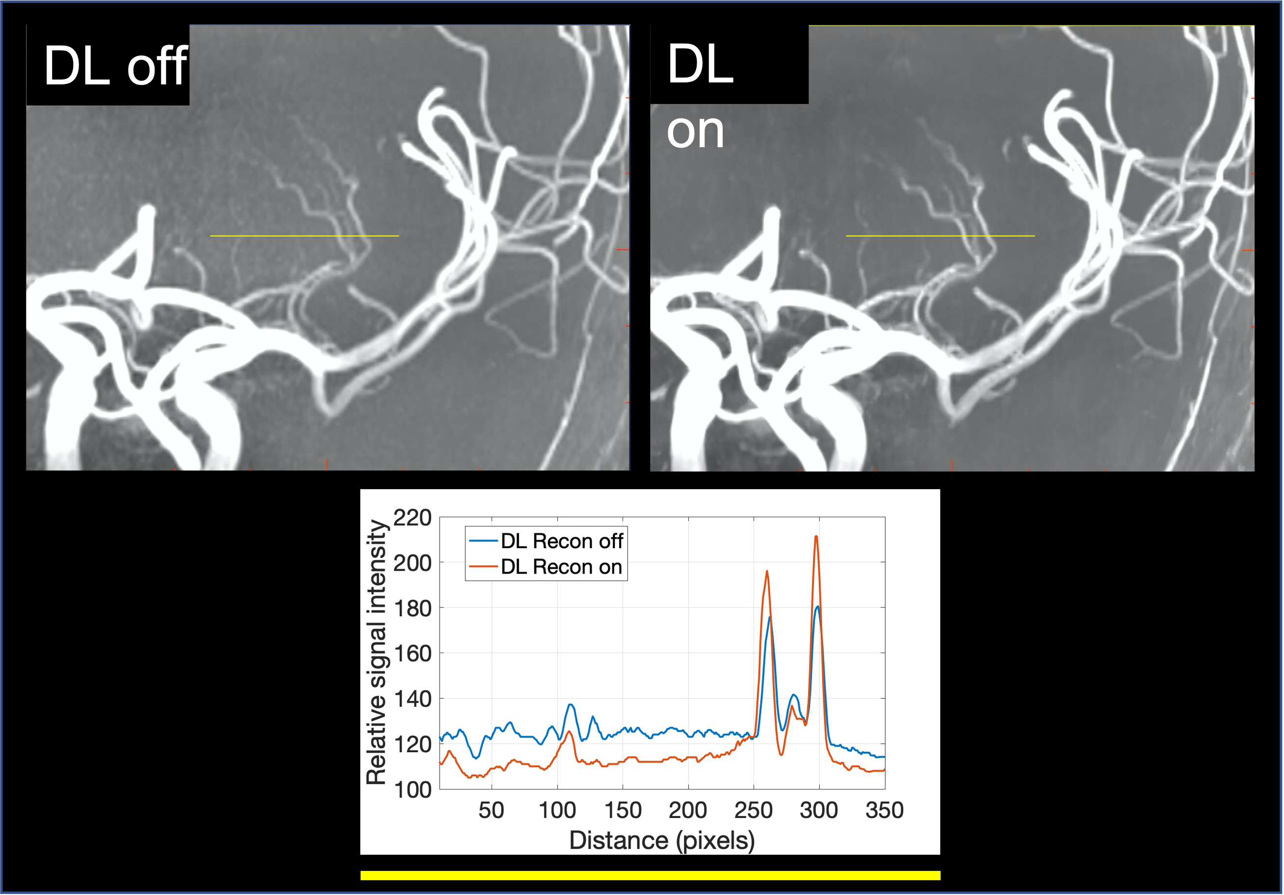
Figure.3. Representative Perforating artery images on 7T to compare the DL recon on and off. The profile plot of yellow line on MIP image showed better peak signal and lower noise floor in the DL Recon on image.
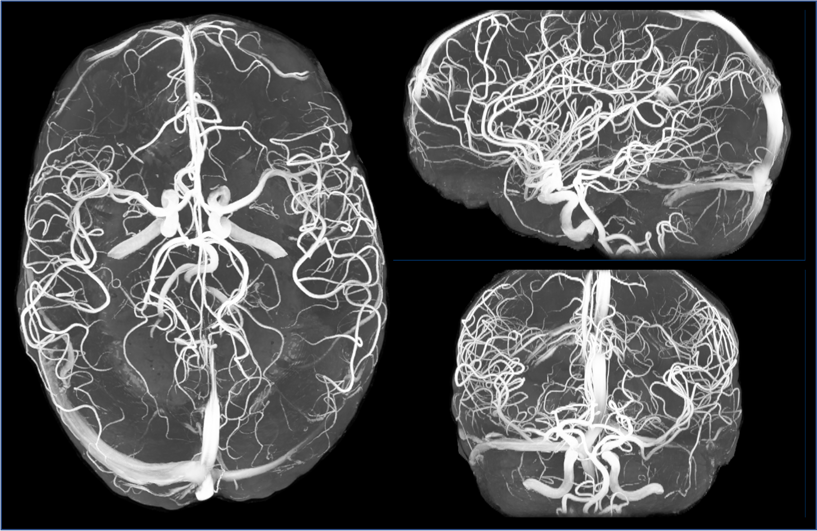
Figure.4. Representative 7T DL reconstructed full MIP MRA image with brain skull stripping.