3165
A Steady State Free Precession CEST Sequence with Short Saturation at 3T Human Scanner1Center for Biomedical Imaging Research, Department of Biomedical Engineering, Tsinghua University, Beijing, China
Synopsis
Keywords: CEST & MT, CEST & MT
In this study, we proposed a steady state free precession CEST sequence with short saturation at 3T scanner. Our contributions are: 1) We investigated the SSFP process containing chemical saturation pulses and gave an approximate analytic solution. 2) Simulation and phantom results revealed that the proposed SSFP-CEST sequence had higher SNR and higher saturation efficiency than previous steady-state CEST, while the acquisition time was relatively short.Introduction
Chemical exchange saturation transfer (CEST) MRI is a promising ‘label-free’ molecular imaging tool that is capable of measuring endogenous solutes. However, it’s dependent on sequence design and acquisition parameters. Two fast acquisition scheme are currently described[1], steady-state[3][5] (SS) and pseudo steady-state (PS) acquisition.In this study, we proposed a CEST-weighted steady state free precession sequence (SSFP-CEST). Our contributions are: 1) We investigated the SSFP process containing short saturation pulses and gave an approximate analytic solution. 2) Simulation and phantom results revealed that the proposed SSFP-CEST sequence had higher SNR and higher saturation efficiency than previous steady-state CEST, while the acquisition time was relatively short.
Methods
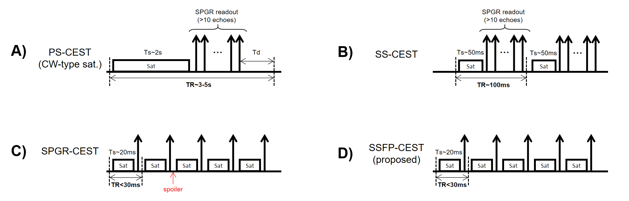
Principle of SSFP-CESTThe schematic of proposed SSFP-CEST sequence is shown in Figure 1. SSFP-CEST has three differences with previous steady-state CEST sequence: 1) SSFP-CEST has a short TR (<30ms) and no spoiler gradient. Mxy with saturation information is continuously utilized in subsequent acquisitions, avoiding the waste of CEST contrast due to SPGR acquisition. 2) Due to the absence of spoiler gradient, Mxy’s effect is not negligible. When a saturation pulse is applied, the chemical exchange effect happens on both z-axis and x-y plane thus increasing the saturation efficiency. 3) SSFP acquisition naturally has a high SNR, which helps to improve the quality of CEST imaging[4].
SSFP-CEST Magnetization: An Approximate Analytic Solution
Here we present an approximate analytic solution of SSFP-CEST[2]. The magnetization evolution for static spins can be described using rotation matrix R and siganl decay matrix E:
$$\begin{array}{l}M_{n}^{\prime}=R_{z}(\theta)E\left(R_{1},R_{2},T_{D}\right)R_{x}(\alpha)M_{n-1}+\left(1-e^{-R_{1}T_{D}}\right)M_{0}\\M_{n}=E\left(R_{1\rho},R_{2\rho},T_{S}\right) M_{n}^{\prime}+\left(1-e^{-R_{1 \rho}T_{S}}\right)M_{SS, z}\end{array}$$
$$R_{z}(\theta)=\left[\begin{array}{ccc}\cos(\theta)&\sin(\theta)&0\\-\sin(\theta)&\cos(\theta)&0\\0&0&1\end{array}\right],E\left(R_{1},R_{2},T\right)=\left[\begin{array}{ccc}e^{-R_{2}T}&0&0\\0&e^{-R_{2}T}&0\\0&0&e^{-R_{1}T}\end{array}\right],R_{x}(\alpha)=\left[\begin{array}{ccc}1&0&0\\0&\cos (\alpha)&\sin(\alpha)\\0&-\sin(\alpha)&\cos(\alpha)\end{array}\right]$$
where Mn and Mn' are the magnetization at the end of nth TR and after saturation. M_SS is the steady-state magnetization after a infinitely long saturation pulse. From eqns above we have:
$$M_{n}=AM_{n-1}+B$$
where
$$\begin{aligned}A&=E\left(R_{1\rho},R_{2\rho},T_{S}\right)R_{z}(\theta)E\left(R_{1},R_{2},T_{D}\right) R_{x}(\alpha)\\&=\left[\begin{array}{ccc}*&*&e^{-R_{2}T_{D}-R_{2 \rho}T_{S}}\sin(\theta)\sin(\alpha) \\*&*&e^{-R_{2}T_{D}-R_{2 \rho}T_{S}}\cos(\theta)\sin(\alpha)\\0&-e^{-R_{1}T_{D}-R_{1\rho}T_{S}} \sin(\alpha)&e^{-R_{1}T_{D}-R_{1\rho}T_{S}}\cos (\alpha)\end{array}\right]\end{aligned}$$
$$\begin{aligned}B &=E\left(R_{1\rho},R_{2 \rho},T_{S}\right)\left(1-e^{-R_{1}T_{D}}\right)M_{0}+\left(1-e^{-R_{1 \rho} T_{S}}\right) M_{S S, z}\\&=\left[\begin{array}{c}0 \\0 \\e^{-R_{1\rho}T_{S}}\left(1-e^{-R_{1} T_{D}}\right)M_{0}+\left(1-e^{-R_{1 \rho}T_{S}}\right) M_{SS,z}\end{array}\right]\end{aligned}$$
For small flip angels used in our study, we think Mxy from 2 or more previous TR has a negligible contribution to Mz. Under this approximation, $$$M_{n}=A^{2} M_{n-2}+(A+I) B$$$. We solely considered Mz due to its determination on signal intensity. When Mz reach steady state $$$\left(M_{n}==M_{n-2}\right)$$$, finally we obtained:
$$\begin{aligned}M_{\text{final },z} &=\frac{(1+A(3,3)) B(3)}{1-A^{2}(3,3)}\\&=\frac{\left(1+e^{-R_{1} T_{D}-R_{1\rho}T_{s}}\cos(\alpha)\right)\left(e^{-R_{1 \rho}T_{S}}\left(1-e^{-R_{1}T_{D}}\right) M_{0}+\left(1-e^{-R_{1\rho}T_{S}}\right)M_{S S, z}\right)}{1-e^{-2\left(R_{1}T_{D}+R_{1\rho}T_{S}\right)} \cos ^{2}(\alpha)-e^{-\left(R_{1}T_{D}+R_{1\rho}T_{s}\right)}e^{-\left(R_{2}T_{D}+R_{2\rho}T_{S}\right)}\sin ^{2}(\alpha)\cos (\theta)}\end{aligned}$$
Let
$$E_{1, app}=\sqrt{e^{-2\left(R_{1}T_{D}+R_{1}T_{S}\right)}\cos ^{2}(\alpha)-e^{-\left(R_{1} T_{D}+R_{1} T_{S}\right)}e^{-\left(R_{2}T_{D}+R_{2\rho}T_{S}\right)}\sin ^{2}(\alpha)\cos(\theta)}$$
then the signal evolution of SSFP-CEST can be expressed as:
$$\begin{aligned}M_{n,z}&=A^{2}(3,3)M_{n-2,z}+(1+A(3,3))B(3)\\&=E_{1,app}^{n}M_{\text{ini,z}}+\left(\sum_{k=0}^{n/2}E_{1, app}^{2k}\right)\left(1-E_{1,app}^{2}\right)M_{final,z}\\&=E_{1, app}^{n}\left(M_{\text{ini,z}}-M_{\text {final,z}}\right)+M_{\text {final,z}}\end{aligned}$$
As above, the Mz signal of SSFP-CEST change from inital state Mini,z to steady state Mfinal,z at the rate of E1,appn.
Bloch-McConnell Simulation
We compared SSFP-CEST with SS-CEST and PS-CEST through a two-pool (water-amide) Bloch-McConnel equation simulation. Main parameters were: B0=3T, B1=0.7T, T1water=1000ms, T2water=100ms, flip angle=10°, voxel size=1mm3, number of spin per voxel=100, gradient net area in each TR is 6mT*ms/m, famide=0.01, kex=39. For SSFP-CEST and SPGR-CEST, Ts=20ms, Td=10ms. For SS-CEST, Ts=50ms, Td=42ms, TFE factor=12. For PS-CEST, Ts=2s, TFE factor=50.
Phantom Experiment
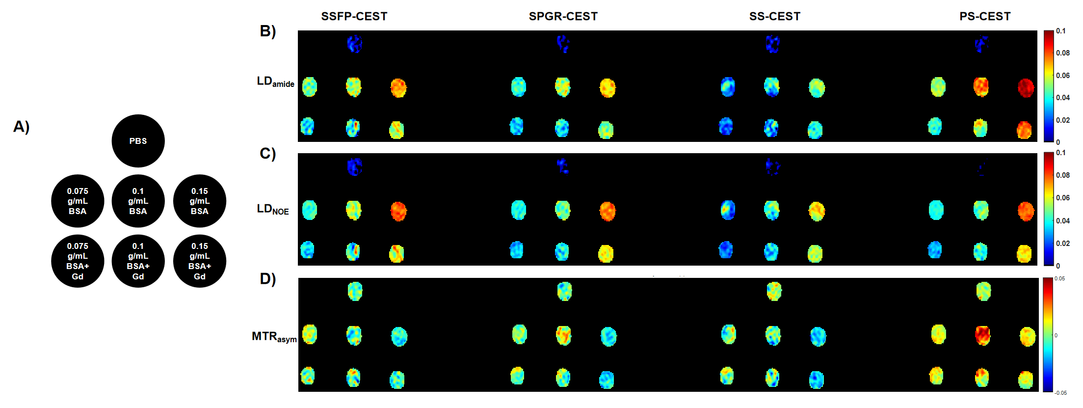
The phantom contains 7 tubes of different BSA concentration. Phantom experiment were performed on a 3T scanner (Ingenia CX 3.0T; Philips Medical Systems, Best, The Netherlands), using a body coil for transmission and a 32-channel head coil for reception. Scan parameters were consistent with simulation except that the TFE factor of PS-CEST is 25. A 2D scan (SENSE=1) was performed at 24 saturation offsets for Z-spectra fitting, distributed from -10 ppm to 10ppm. For steady state sequences, each offset was repeated for 5times to reach steady state.
Results and Discussion
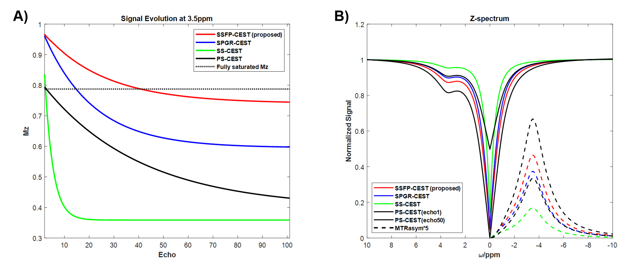
SimulationAs shown in Figure 2(A), SSFP-CEST has the highest signal intensity of three steady state sequence. The first echo of PS-CEST is very close to the fully saturated Mz signal, but as the number of echoes increases, PS-CEST gradually departs from saturation steady-state and the signal intensity gradually decreases. Only about the first 10 echoes of PS-CEST have larger signal intensity than SS-CEST, indicating that PS-CEST may has worse SNR and saturation contrast than SSFP-CEST due to large TFE factor under 3D acquisition, despite its long scan time. In terms of Z-spectrum and MTR asymmetry, SSFP-CEST has the best CEST contrast in steady state sequence (Figure 2(B)).
Phantom Results
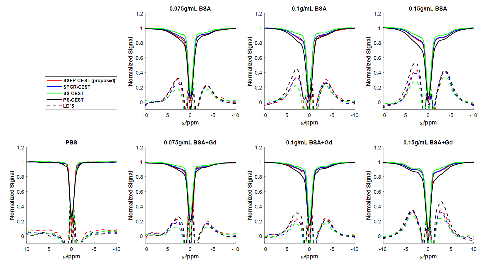
Figure 3 and 4 depicts the CEST contrast maps and corresponding Z-spectrum of BSA phantom. SSFP-CEST is capable of producing high-quality CEST contrast, superior to other steady state sequences, while being close to PS-CEST but with shorter scan time.In terms of scan time, SSFP-CEST and SPGR-CEST takes 1min 24s while SS-CEST takes 36 seconds. PS-CEST . Noted that SSFP-CEST can be further accelerated by shortening Ts and increasing echo number (currently 1). Besides, similar to other 3D steady-state acquisitions, SSFP-CEST does not require repeated offsets to reach steady state, since the k-space peripheral signal will be acquired first, which ensures the fast acquisition of SSFP-CEST.
Conclusion
In this study, we developed a SSFP-CEST sequence by adding short saturation pulse to SSFP sequence. The preliminary simulation and phantom experiment results indicated that SSFP-CEST can improve the SNR and saturation efficiency of SS-CEST, enabling a comparable CEST contrast to PS-CEST. Besides, the hypothesis of the presence of chemical exchange effects in the x-y plane was preliminarily confirmed.Acknowledgements
This work was supported by the National Natural Science Foundation of China [grant numbers 82071914]References
[1] Khlebnikov V, Geades N, Klomp DWJ, Hoogduin H, Gowland P, Mougin O. Comparison of pulsed three-dimensional CEST acquisition schemes at 7 tesla: steady state versus pseudosteady state. Magn Reson Med. 2017 Jun;77(6):2280-2287. doi: 10.1002/mrm.26323. Epub 2016 Jul 25. PMID: 27455028; PMCID: PMC5484355.
[2] Li L, Miller KL, Jezzard P. DANTE-prepared pulse trains: a novel approach to motion-sensitized and motion-suppressed quantitative magnetic resonance imaging. Magn Reson Med. 2012 Nov;68(5):1423-38. doi: 10.1002/mrm.24142. Epub 2012 Jan 13. PMID: 22246917.
[3] Jones CK, Polders D, Hua J, Zhu H, Hoogduin HJ, Zhou J, Luijten P, van Zijl PC. In vivo three-dimensional whole-brain pulsed steady-state chemical exchange saturation transfer at 7 T. Magn Reson Med. 2012 Jun;67(6):1579-89. doi: 10.1002/mrm.23141. Epub 2011 Nov 14. PMID: 22083645; PMCID: PMC3291747.
[4] Shah T, Lu L, Dell KM, Pagel MD, Griswold MA, Flask CA. CEST-FISP: a novel technique for rapid chemical exchange saturation transfer MRI at 7 T. Magn Reson Med. 2011 Feb;65(2):432-7. doi: 10.1002/mrm.22637. Epub 2010 Oct 11. PMID: 20939092; PMCID: PMC3760737.
[5] Sui R, Chen L, Li Y, Huang J, Chan KWY, Xu X, van Zijl PCM, Xu J. Whole-brain amide CEST imaging at 3T with a steady-state radial MRI acquisition. Magn Reson Med. 2021 Aug;86(2):893-906. doi: 10.1002/mrm.28770. Epub 2021 Mar 27. PMID: 33772859; PMCID: PMC8076068.
Figures