3126
Improving interpretation accuracy for curved planar reformation of intracranial vessel wall MRI by reducing intra-plane rotation1Department of Electrical and Computer Engineering, University of Washington, Seattle, WA, United States, 2Department of Bioengineering, University of Washington, Seattle, WA, United States, 3Department of Radiology, University of Washington, Seattle, WA, United States, 4Department of Surgery, University of Washington, Seattle, WA, United States, 5Department of Radiology, University of North Carolina-Chapel Hill, Chapel Hill, NC, United States
Synopsis
Keywords: Data Processing, Visualization
This work aims to develop an algorithm for straightened curved planar reformation (CPR), i.e., extracting the 2D cross-sectional images along a vessel centerline in a vessel wall MRI scan. Previous methods determine the orientation of CPR images in a fixed way, leading to undesired rotation along the centerline. Our method instead calculates the local coordinate system with respect to previous slices, thus keeping the continuity of cross-sections. Our CPR results show a better readability of the straightened vessel image, especially when one wants to utilize the spatial information among adjacent CPR slices for a more comprehensive and accurate medical analysis.Introduction
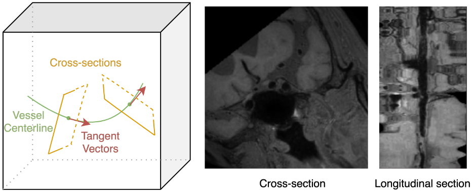
Vessel assessment using intracranial vessel wall MRI is important for stenosis detection and vascular plaque assessment1. Due to their tortuous nature, intracranial vessels could be hard to visualize and label in original 3D space. Curved planar reformation (CPR, Figure 1) aims to ameliorate this issue by extracting the cross-sectional images along the vessel centerline2,3. Recently, 3D quantification of lumen and wall shape and plaque components has leveraged such CPR images to produce reliable results4. However, previous CPR methods could produce excessive rotation along the normal direction of the cross-section. This may interfere with image analysis that utilizes the spatial information of adjacent cross-sections, thus undermining the interpretation accuracy. To address this problem, we propose a CPR algorithm that considers the variation of the tangent vector along the centerline to determine the basis of the local coordinate system for each section, thereby reducing the undesired rotation and improving the continuity of the straightened image.Method
A tracked vessel centerline in the original 3D image is modeled as a sequence of 3D points $$$(p^k)_{k=1}^K$$$, where $$$K$$$ is the number of points on the centerline. Let the unit tangent vector at $$$p^k$$$ be $$$t^k$$$, and the orthonormal basis for the cross-sectional plane through $$$p^k$$$ be $$$\{u^k,v^k\}$$$, where $$$u^k,v^k$$$ are two 3D unit vectors satisfying$$
\begin{cases}
|u^k|=|v^k|=1\\
u^k\bot v^k\\
u^k\bot t^k,v^k\bot t^k
\end{cases}
$$
The third row is from the fact that $$$t^k$$$ is also the normal vector of the cross-sectional plane. Once $$$u^k$$$ and $$$v^k$$$ are determined, one can calculate the 3D coordinates of the grid points $$$\{g_{ij}^k\}$$$ on the cross-sectional plane by $$$g_{ij}^k=p^k+iu^k+jv^k$$$, where $$$I\in[-W/2,W/2],j\in[-H/2,H/2]$$$, and $$$W,H$$$ are the width and height of the cross-sectional image to extract, respectively. Then, the cross-section through $$$p^k$$$ can be generated by interpolating the pixel values of $$$\{g_{ij}^k\}$$$.
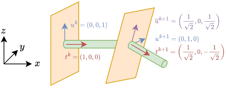
A crucial step is to determine the basis $$$\{u^k,v^k\}$$$ for each cross-sectional plane. There are a total of 6 parameters for these two 3D vectors, but the aforementioned system of equations only provides 5 constraints, therefore, there are an infinite number of solutions. Indeed, one can intuitively confirm this by rotating $$$u^k,v^k$$$ along the tangent vector while keeping the orthogonality. Previous CPR methods usually introduce an additional constraint, such as forcing the first component (coordinate) $$$u_x^k$$$ of the vector $$$u^k$$$ to be 0, to obtain a unique solution. However, such constraint may cause undesired rotation (Figure 2) of the basis, as it is imposed independently on each cross-sectional plane, and does not respect the spatial association of consecutive $$$p^k$$$’s.
To address this issue, we propose to calculate the rotation matrix $$$R^k$$$ that transforms the tangent vector of previous point to the current one, i.e., $$$t^{k+1}=R^kt^k$$$. The matrix can be obtained by Rodrigues' rotation formula5, and the only indeterminate case is when $$$t^k$$$ and $$$t^{k+1}$$$ are in exactly opposite directions, which does not happen in practice and thus we do not need to worry about it. Once $$$R^k$$$ is obtained, the basis for the next cross-section is computed recursively by
$$
u^{k+1}=R^ku^k,v^{k+1}=R^kv^k
$$
Since rotation matrices are orthogonal, one can validate that the basis vectors will satisfy the aforementioned system of linear equations, as long as $$$u^1,v^1$$$ does. We can choose $$$u^1,v^1$$$ arbitrarily, for example, by similar ways to previous CPR methods. Therefore, our algorithm is completely established.
Intuitively, when moving along the centerline, the 3D rotations of the cross-section and the tangent vector (namely the vessel direction) are synchronous in the proposed algorithm. Thus, the undesired rotation along the normal axis is minimized in some sense.
Results
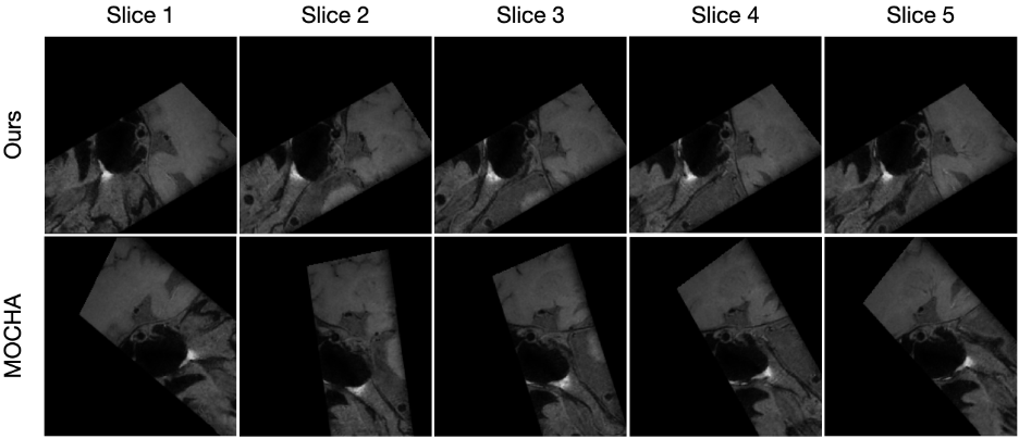
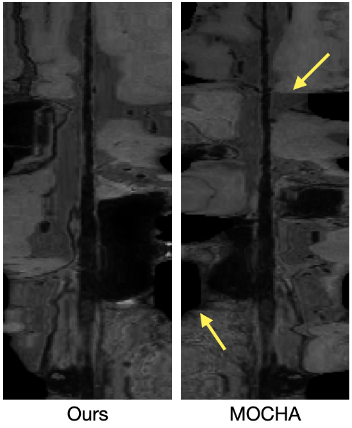
We compared the proposed algorithm with a previous method from MOCHA, a multiplanar reconstruction tool6, in the task of CPR for intracranial T1-weighted MRI (Figure 3). It is demonstrated that our method improves the continuity among adjacent slices and minimizes intra-plane rotation. This can also be confirmed from the longitudinal sections (Figure 4) of the straightened vessel, where the conventional method leads to obvious discontinuity, due to abrupt rotation of corresponding cross-sections.Discussion and Conclusion
The rotation matrix-based method proposed in this work shows promising results for curved planar reformation in terms of alleviating intra-plane rotation. Such twist-free straightened vessel images are useful not only for human review but also for some image processing models. For example, some deep learning networks for segmentation rely on 2.5D images, i.e., several consecutive 2D CPR slices. Cross-sections without excessive rotation allow such networks to better capture spatial information along the vessel, thus improving prediction accuracy.Acknowledgements
No acknowledgement found.References
1. Mandell, D. M., et al. "Intracranial vessel wall MRI: principles and expert consensus recommendations of the American Society of Neuroradiology." American Journal of Neuroradiology 38.2 (2017): 218-229.
2. Klok, Fopke. "Two moving coordinate frames for sweeping along a 3D trajectory." Computer Aided Geometric Design 3.3 (1986): 217-229.
3. Kanitsar, Armin, et al. CPR-curved planar reformation. IEEE, 2002.
4. Sun, Jie, et al. "Characterization of non-stenotic plaques in intracranial arteries with multi-contrast, multi-planar vessel wall image analysis." Journal of Stroke and Cerebrovascular Diseases 31.10 (2022): 106719.
5. Dai, Jian S. "Euler–Rodrigues formula variations, quaternion conjugation and intrinsic connections." Mechanism and Machine Theory 92 (2015): 144-152.
6. Guo, Yin, et al. "Multi‐planar, multi‐contrast and multi‐time point analysis tool (MOCHA) for intracranial vessel wall characterization." Journal of Magnetic Resonance Imaging56.3 (2022): 944-955.
Figures