2876
A novel PNS measurement setup for body gradient coils at an ultrasonic driving frequency of 20kHz1Radiology, University Medical Center Utrecht, Utrecht, Netherlands, 2Spinoza Center for Neuroimaging, Amsterdam, Netherlands
Synopsis
Keywords: Gradients, Gradients
Large dB/dt swings in gradient coils can induce peripheral nerve stimulation (PNS) in the human body. This limits the slew rates used in whole-body MRI reducing scan speeds and spatial resolution. Ultrasonic head gradients can enable fast and silent imaging, however extension to whole-body gradients is challenging due to the required larger dB/dt swings. In this work, we present a body gradient coil which can be used to investigate PNS induction at an ultrasonic driving frequency of 20kHz.
Introduction
Peripheral nerve stimulation (PNS) originates from the rapid switching of magnetic fields in the human body which interacts with the nervous system. In MRI scans, the source of PNS induction arises from large dB/dt swings from the gradient coil magnetic fields which are used for spatial encoding1. This can cause discomfort in patients and in extreme cases lead to heart difficulties if cardiac nerves are stimulated2. To avoid these issues, PNS thresholds limit the maximum slew rates possible during scans which results in slower spatial encoding and lower spatial resolution. This limits the applicability of fast MRI techniques. Previously, we presented a silent head gradient that switches ultrasonically at 20 kHz without any substantial PNS3. Since not all MR exams image the brain, we are exploring to extend this to a silent whole-body gradient. However, body gradients need to encode a larger FOV, therefore, for the same gradient strength as in brain imaging, they feature higher dB/dt swings and are more likely to induce PNS. In previous work, PNS thresholds for the arm have been shown to be greatly reduced for driving frequencies of 20kHz, highlighting potential PNS threshold limitations for silent whole-body gradient development4. In this work, we present a setup for testing PNS in an ultrasonically switched body gradient that enables us to test multiple body parts and demonstrate no PNS in arms/legs at more than 2000T/m/s and no PNS at 1000T/m/s when driven at the inaudible frequency of 20kHz.Methods
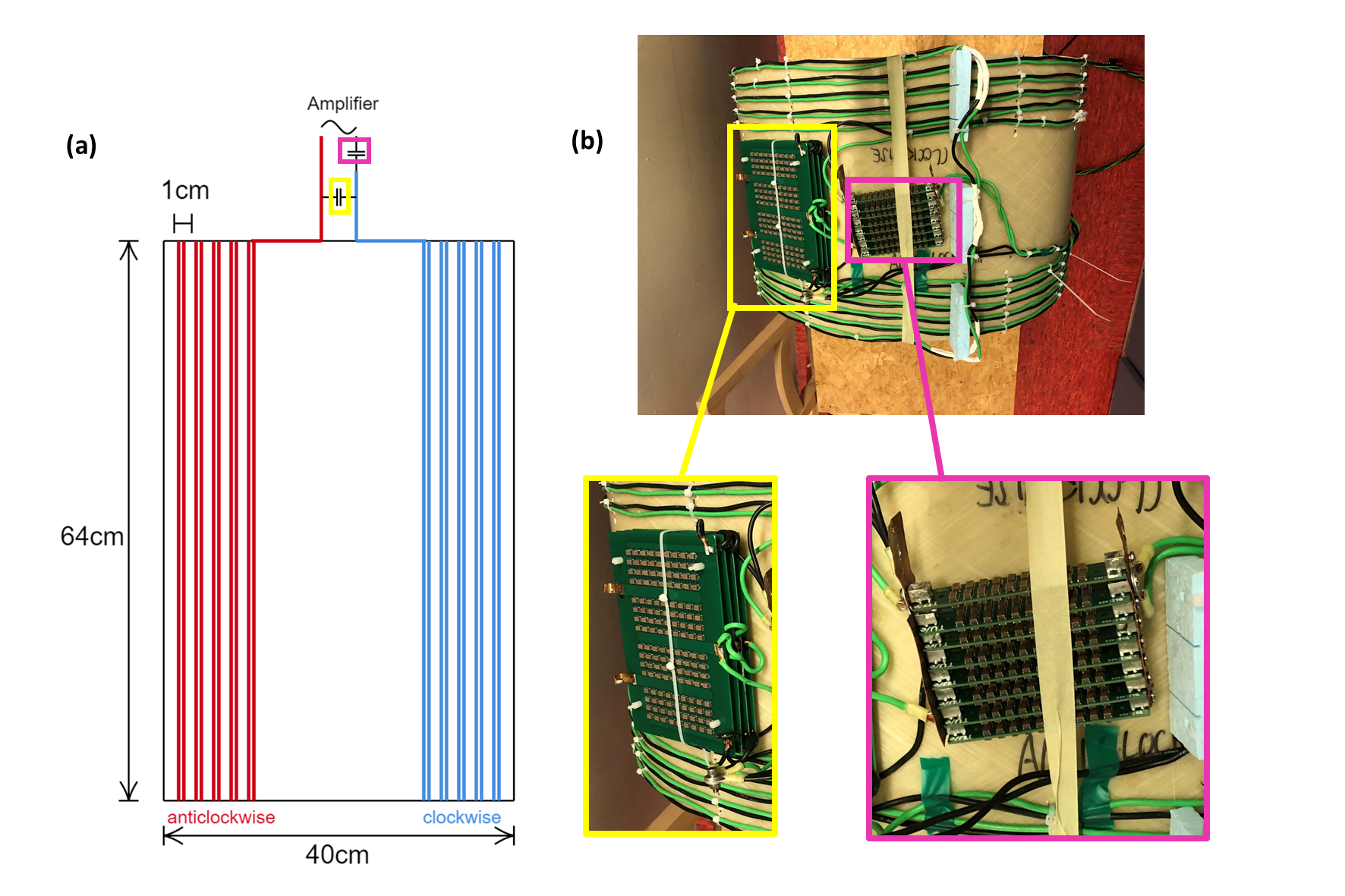
A z-axis body gradient coil of length 40cm was constructed with a 64cm diameter fibreglass bore. At each end of the fibreglass bore, five copper windings were made. This was done twice with two separate wires of copper to half the resistance (Figures 1a-b). On one end, the windings were made clockwise and at the opposing end, windings were made anticlockwise to ensure a z-gradient field was formed. This led to an increasing gradient field from the centre of the bore ensuring PNS would occur for a high enough current. The distance between adjacent coil windings was maintained at 1cm.The measured inductance and resistance of the coil was 52.1 µH and 71.2 mΩ, respectively. Two capacitor banks were created. One bank was placed in series with the amplifier and had a value of 332nF. The second bank was placed in parallel to the amplifier and had a value of 890nF (Figure 1b). This allowed a coil resonance frequency of 19.85kHz matched to an impedance of 1 Ω.
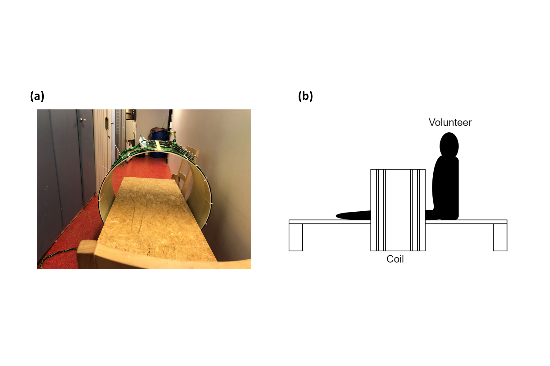
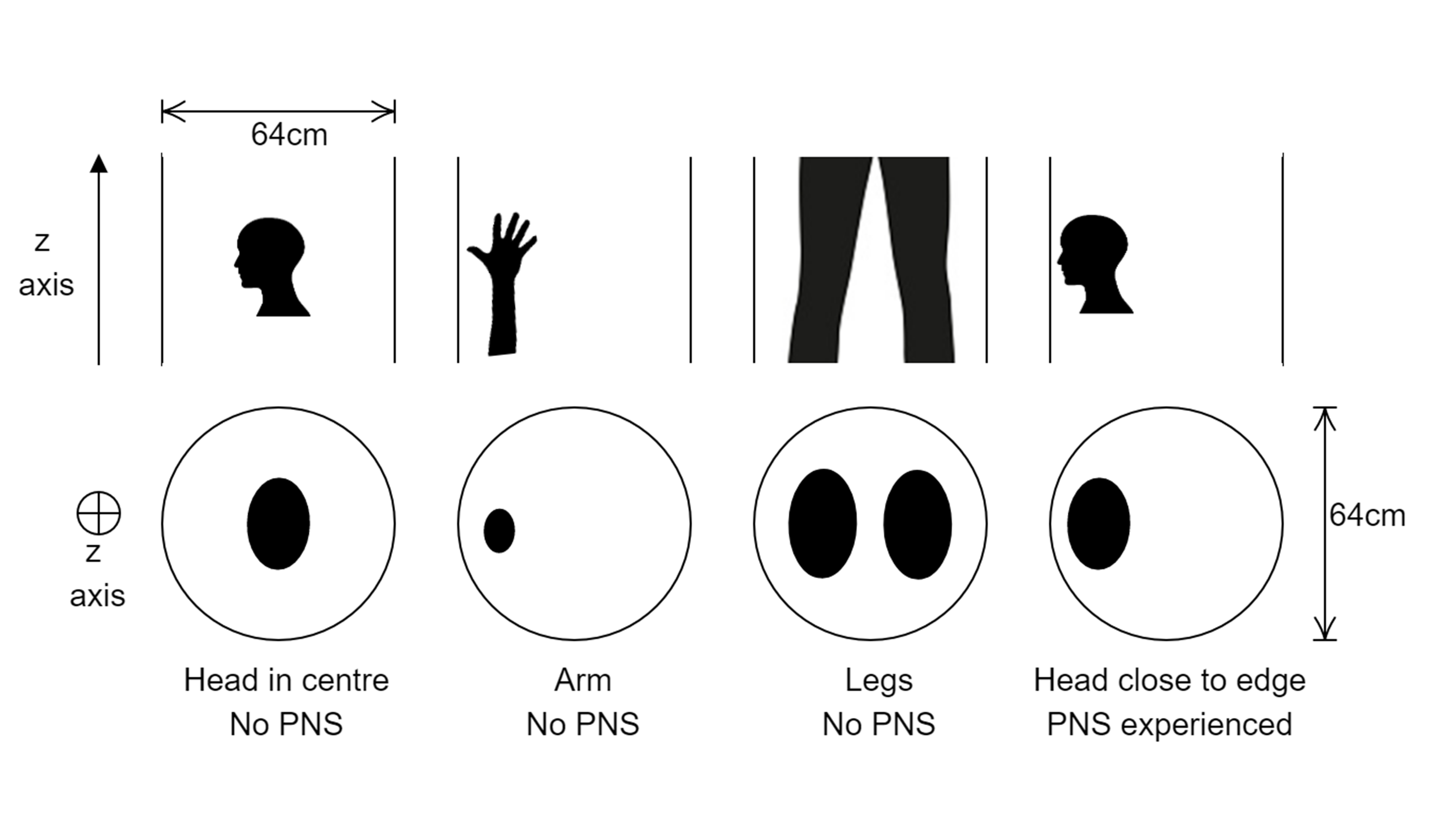
The body gradient coil was combined with a wooden platform allowing volunteer placement within the coil (Figures 2a-b). The body coil was connected to a modified gradient amplifier (Prodrive). A volunteer was placed in the setup in four different positions, as indicated in figure 3 to test whether the setup was powerful enough to induce PNS. PNS inducement was investigated in the arm, legs and the head of the volunteer.
Field maps of the coil were calculated using Biot-Savart and were based on the measured location of the conducting windings. The current supplied to the coil was measured using the current monitoring from the amplifier. A circuit simulator (LTSpice) was used to predict the current in the coil from the supplied current from the amplifier.
Results
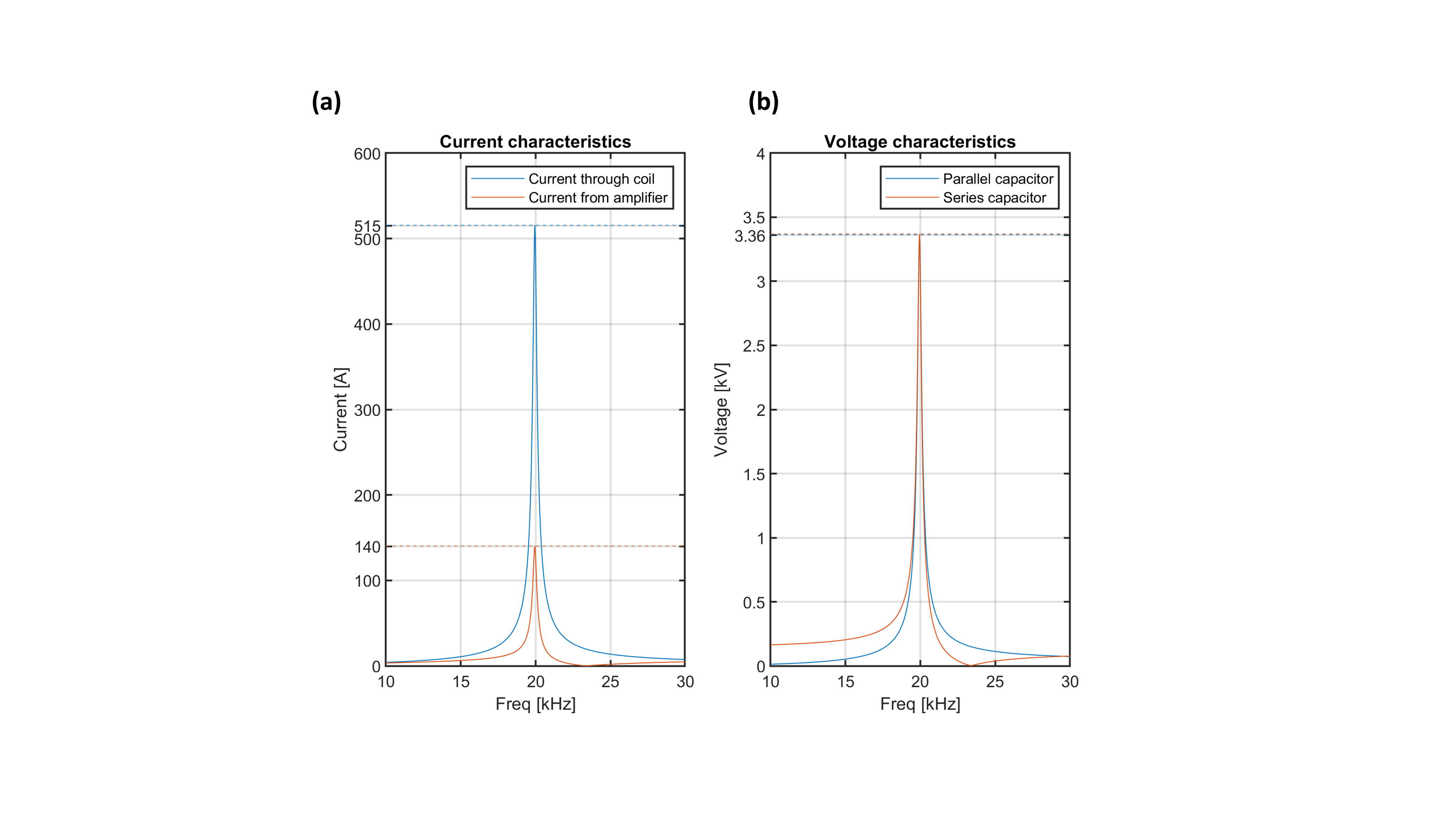
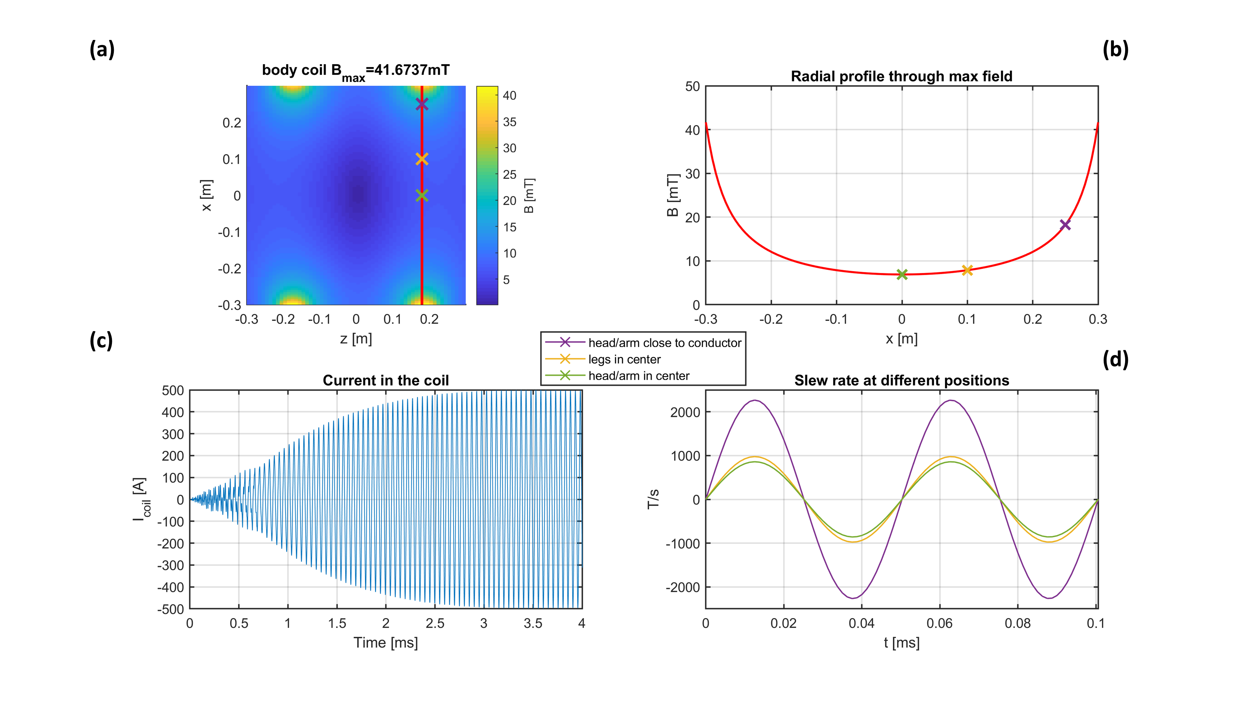
Figure 4 shows the predicted voltages over the capacitor banks and current through the coil for the driving voltage used for the PNS tests. Here, a maximum voltage of ~3.3 kV is predicted over the capacitor banks which yields 515 A of current through the coil.Figure 5a shows the field map from the coil for a current of 500 A. Note that the highest field amplitudes are observed close to the conductors at a distance of around 30 cm from the centre of the coil. Here, the markers indicate the testing positions for the arm, leg and head of the volunteer. The maximum field amplitude at these positions is shown in Figure 5b. Figure 5c shows the current in the coil when doing the PNS experiments. This was shown to achieve a maximum current through the coil of ~500 A matching theoretical predictions (Figure 4a). The slew rate over time is shown in figure 5d with a maximum of 2267 T/s for a position close to the conductor.
No PNS was felt in the arm or legs. Nerve density is greater in the face therefore it was predicted that placing the head in the bore would provide an increased chance of noticeable PNS. Positioning the head in the centre of the bore also did not induce any noticeable PNS. Positioning the volunteer head closer to the coil’s outer radius (~30cm from centre) led to noticeable PNS (Figure 3), which was expected due to the more than two-fold increase in dB/dt compared to the centre of the bore (Figure 5d).
Conclusion
We presented a novel setup to test PNS for ultrasonically switched body gradients that will allow us to assess PNS in different body parts at 20 kHz. This setup can be used to investigate the PNS limitations of ultrasonically switched body gradients beyond 2000T/m/s, an order of magnitude more than typically available for body gradients.Acknowledgements
No acknowledgement found.References
1. Davids M, Guerin B, Schad LR, Wald LL, Peripheral Nerve Stimulation Modeling for MRI. eMagRes, 2019, Vol 8: 87–102. DOI 10.1002/9780470034590.emrstm1586
2. Ham CL, Engels JM, van de Wiel GT, Machielsen A. Peripheral nerve stimulation during MRI: effects of high gradient amplitudes and switching rates. J Magn Reson Imaging. 1997 Sep-Oct;7(5):933-7. doi: 10.1002/jmri.1880070524. PMID: 9307922.
3. Versteeg E, Klomp DWJ, Siero JCW. A silent gradient axis for soundless spatial encoding to enable fast and quiet brain imaging. Magn Reson Med. 2022 Feb;87(2):1062-1073. doi: 10.1002/mrm.29010. Epub 2021 Sep 21. PMID: 34545956; PMCID: PMC9293127.
4. Saritas EU, Goodwill PW, Zhang GZ, Conolly SM. Magnetostimulation limits in magnetic particle imaging. IEEE Trans Med Imaging. 2013 Sep;32(9):1600-10. doi: 10.1109/TMI.2013.2260764. Epub 2013 Apr 30. PMID: 23649181.
Figures