2875
MRI Gradient Induced Vibration of Leadless Pacemakers1Abbott, Sylmar, CA, United States, 2Abbott, Sunnyvale, CA, United States
Synopsis
Keywords: Safety, Safety, Implants
Simulations were performed to assess potential gradient induced vibration of leadless pacemakers. Results of the evaluation showed leadless pacemakers sized objects, made from commonly used conductive materials, generated very small vibrations (all less than 0.3mm in displacement) when exposed to conservative gradient induced vibration safety test conditions per ISO/TS 10974. These calculated displacements are negligible in comparison to the interacting displacements between a typical leadless pacemaker and cardiac tissue through each cardiac cycle. As such, the risk of leadless pacemaker gradient induced vibration tissue damage is minimal and assessments for this hazard per ISO/TS 10974 may not be necessary.Introduction
For the assessment of MR conditional safety there are many hazards to consider. Gradient induced vibration is one hazard identified in ISO/TS 10974. The pulsed magnetic field (dB/dt) produced by the imaging gradients of an MRI system can induce eddy currents on the conductive surfaces of an of Active Implantable Medical Device (AIMD). These eddy currents produce a time varying magnetic moment that interacts with the static magnetic field (B0) causing vibration of the conductive surfaces and, subsequently, the device. The time-varying torques generated by the dB/dt field are proportional to the size of the conductive surface1, where larger objects of the same material will generate stronger vibrations and smaller objects will have less vibration. As such, gradient induced vibration is generally not expected to pose a tissue damage hazard for small passive medical devices2.As leadless pacemakers are relatively small AIMDs, we explore in this abstract the potential gradient induced vibration for this type of device by modeling leadless pacemaker sized objects made from commonly used conductive materials. The results from this modeling are then analyzed to see if the induced vibration is clinically significant.
Methods
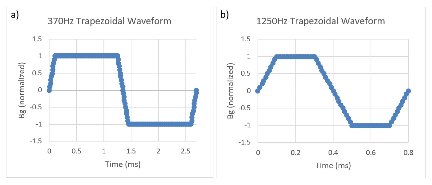
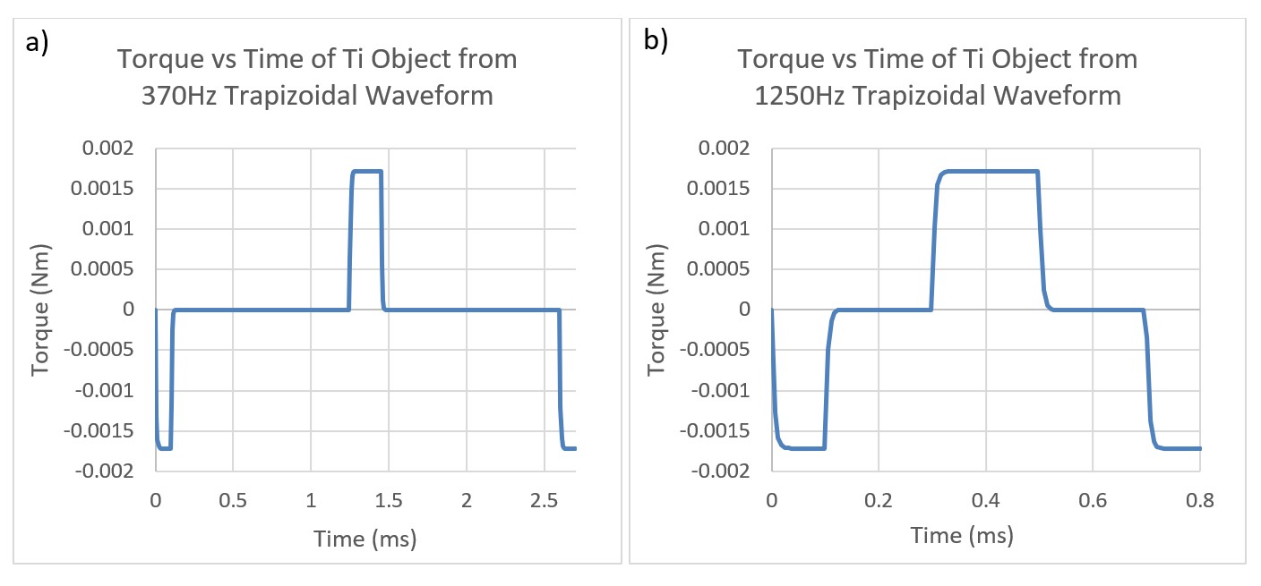
To assess potential gradient induced vibration of leadless pacemakers, simulations were performed using COMSOL Multiphysics software (v6.0). These simulations were conducted on leadless pacemaker sized objects (solid cylinders with length = 38mm and diameter = 6.65mm) constructed from materials commonly used in AIMD batteries (Titanium, Stainless Steel, Aluminum, Nickel, Lithium, CFx, SVO). Battery materials were selected as the battery of a leadless pacemaker makes up the majority of the large conductive surfaces for this device type and is therefore the primary source of MRI induced vibration.The simulations were set up to emulate exposure to the combined gradient and static magnetic fields of a 3T clinical scanner with a maximum gradient slew rate of 200T/m/s per axis. The worst-case pulse sequence waveform characteristics and dB/dt magnitude exposure conditions defined in the MRI induced vibration safety test per ISO/TS 10974 were used. Two trapezoidal gradient waveforms, 370Hz and 1250Hz, were simulated (see Figure 1) with a gradient magnetic field strength of 89.8T/s peak. The gradient magnetic field strength was determined using an implant radius of 20cm which is associated with the compliance volume of MR scanners3. This is considered conservative as the actual implant radius for leadless pacemakers, which reside inside the heart of a patient, will be considerably smaller than this. The gradient waveform frequencies selected span the typical driving frequencies at which 3T MRI scanners are driven at maximum slew rate1.
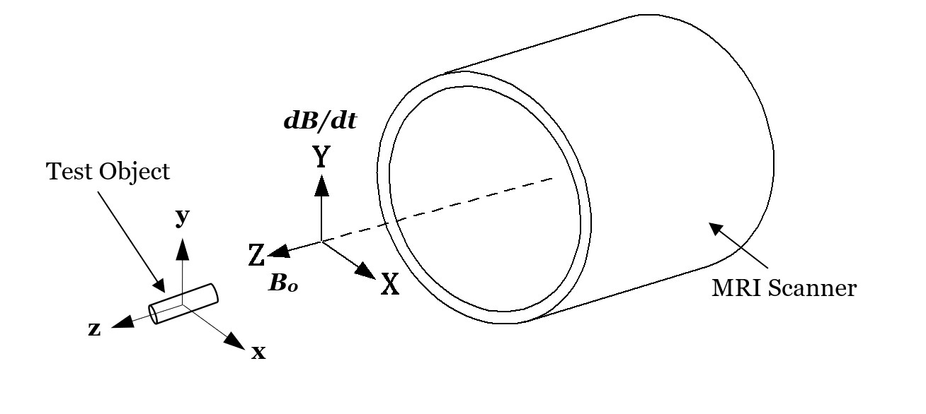
Per ISO/TS 10974 the time-varying forces and torques exerted on a conductive object are proportional to the cross product of the transient dB/dt-induced magnetic moment and the B0 field. These forces and torques are therefore maximized when the AIMD conductive planes are oriented parallel to the B0 field vector and perpendicular to the strongest dB/dt vector. As such, each simulated test object was oriented with its largest conductive plane parallel to the z-axis (B0 field) of the scanner and orthogonal to the y-axis (dB/dt field) of the scanner as shown in Figure 2. The simulations were set up in space with no additional damping forces applied so that the theoretical worst-case displacements from the induced torques could be observed.
Results
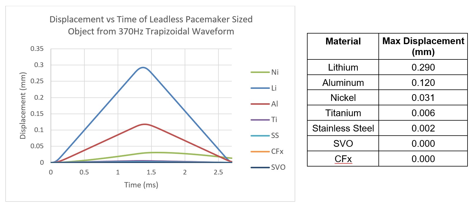
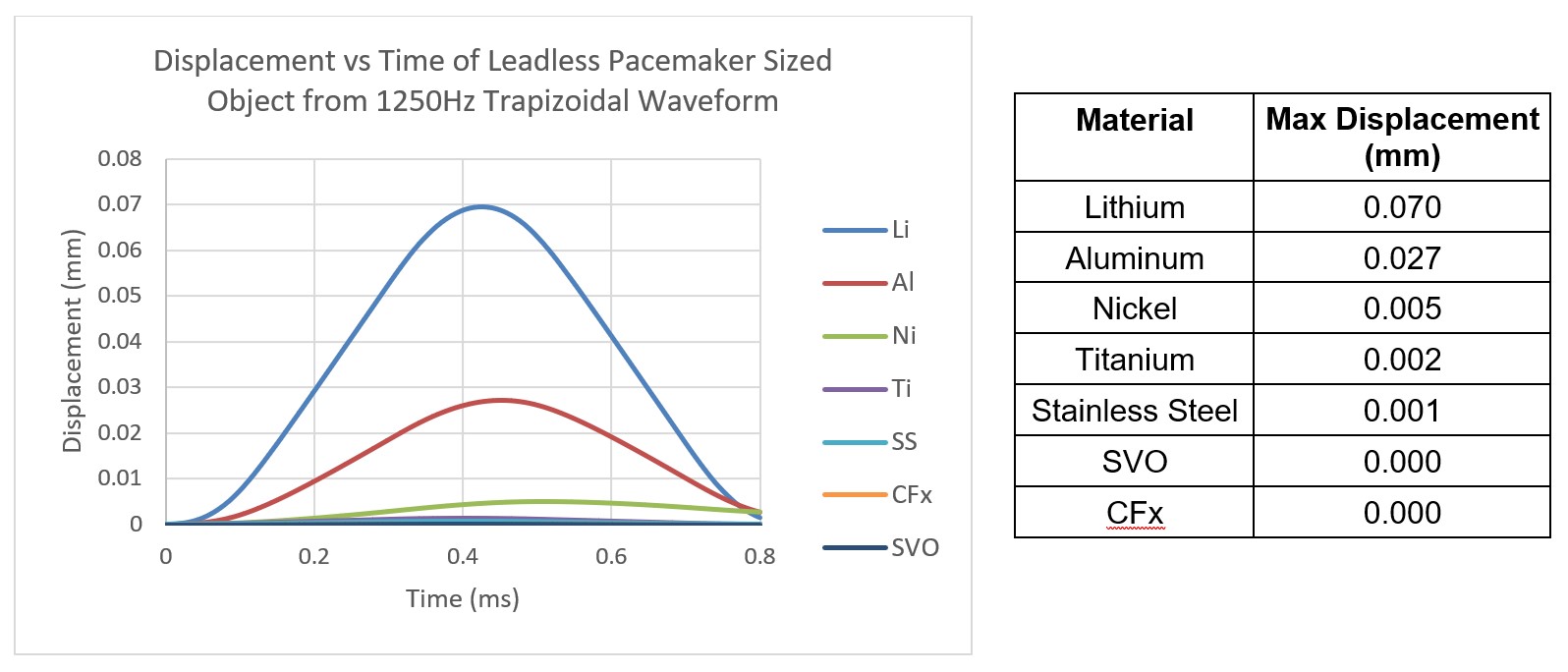
Simulations of gradient induced vibration were conducted for commonly used AIMD materials as described above. The simulation results are shown in Figure 3 and Figure 4. As can be seen in these figures, the maximum displacement produced by the switched magnetic field for the materials modeled is small (<0.3mm), with Lithium, Aluminum, and Nickel producing the largest displacements.Although the dB/dt induced torque generated by the two different waveforms simulated were the same (shown in Figure 5 for Titanium), the 370Hz trapezoidal waveform resulted in ~3x larger displacements than the 1250Hz waveform. This was due to the 370Hz waveform having a longer dwell time between opposing torques allowing for more unrestricted movement. This additional displacement from the 370Hz waveform, however, is likely to be much smaller in-vivo as there are additional structures which will dampen and resist movement during the dwell times.
Discussion/Conclusions
As seen in the results section above, the modeling of leadless pacemaker sized objects resulted in small vibrations with displacements all less than 0.3mm. These simulated objects serve as conservative surrogates for leadless pacemakers as the entire simulated object is constructed from the worst-case material, whereas leadless pacemakers are constructed from a composite of materials which will not all contribute to vibration and will act to dampen the system. Furthermore, the simulations were set up with conservative worst-case exposure conditions and did not include any surrounding structures like cardiac tissue or blood which would further dampen the system. The calculated displacements are negligible in comparison to the interacting displacements between a typical leadless pacemaker and cardiac tissue through each cardiac cycle where the right ventricular apex-to-base dimensional differences at end-systole and end-diastole are estimated at 1.26-1.52cm4. As such, the risk of leadless pacemaker gradient induced vibration tissue damage is minimal and assessments for this hazard per ISO/TS 10974 may not be necessary.Acknowledgements
No acknowledgement found.References
1. ISO/TS 10974, 2018, "Assessment of the safety of magnetic resonance imaging for patients with an active implantable medical device" ISO, Geneva, Switzerland, www.astm.org.
2. Fda.gov, 2021, “Testing and Labeling Medical Devices for Safety in the Magnetic Resonance (MR) Environment, Guidance for Industry and Food and Drug Administration Staff” [online] Available at: https://www.fda.gov/regulatory-information/search-fda-guidance-documents/testing-and-labeling-medical-devices-safety-magnetic-resonance-mr-environment
3. IEC 6061-2-33, 2022, “Medical electrical equipment – Part 2-33: Particular requirements for the basic safety and essential performance of magnetic resonance equipment for medical diagnosis” IEC, Geneva, Switzerland, https://iec.ch.
4. Karatasakis G, Karagounis L, Kalyvas P, et. al. Prognostic Significance of Echocardiographically Estimated Right Ventricular Shortening in Advanced Heart Failure. American Journal of Cardiology 1998; 82: 329-334
Figures