2874
MR conditionality of two MR Conditional DBS ipsilateral implants with separate IPGs
Louai Aldayeh1, Mizan Rahman1, and Ross Venook1
1Boston Scientific Neuromodulation, Valencia, CA, United States
1Boston Scientific Neuromodulation, Valencia, CA, United States
Synopsis
Keywords: Safety, Safety
Previous investigations of RF-induced heating of multiple implants (active as well as passive) have shown that heating of an implant can be impacted by the presence of a separate neighboring implant.
This work assessed to which extend this phenomenon is present for the limited scope of two separate MR Conditional ipsilateral DBS implants, one on one side of the body, and another on the other side. Both, RF-induced heating and voltage injection level into the IPG were assessed.
A variety of DBS lead configurations, and clinically relevant distances in-between the two separate implants, were thoroughly assessed for a data-driven conclusion.
INTRODUCTION
We previously reported on multiple Active Implantable Medical Devices (AIMDs) [1], showing how RF-induced lead electrode heating of an IPG/lead-based system can be impacted by the presence of a neighboring IPG/lead-based system. On the passive implants side, an investigation [2] reported this for adjacent orthopedic implants, and, depending on the length, angle, and proximity gap of the second implant compared to the first, RF-induced heating can potentially increase significantly for specific experimental configurations.This work investigated a specific scenario of two MR Conditional AIMDs: one Deep Brain Stimulation (DBS) implant with the lead and Implantable Pulse Generator (IPG) on the same side of the body (ipsilateral), and another DBS ipsilateral implant on the other side of the body (with a second IPG).
The question was: Given that each of the two separate DBS ipsilateral implants is MR Conditional, what is the MR safety status of the combined system regarding RF-induced distal lead heating and RF-induced voltage injection level into the IPGs from leads?
METHODS
Per the described limited scope, all variants of clinical routings (trajectories) of a DBS ipsilateral implant - whether for pectoral or abdominal IPG locations - were evaluated for range finding of distances between the lead (and IPG) of an Ipsilateral Implant on the one side of the body, to their counterparts of an Ipsilateral Implant on the other side of the body. These ranges of distances between the two implants were explored in testing the two MR-induced hazards likely to be potentially impacted in a multiple-implant setup: RF-induced distal lead heating and RF- induced injection level into the IPG from the lead. Both assessments were done in a 1.5T birdcage radiated testing environment.We applied specific setups in mounting the two DBS implants in the test medium so that each system’s routing has clinically relevant exposure fields. In addition, the mentioned distances between the two separate implants, were thoroughly explored, and for many variants of DBS leads and their mixed configurations. This mounting was implemented in a rectangular ASTM phantom [3] utilizing two circular holders that facilitated the 3D routings and system-to-system distances (See Figures 1 & 2).
Measuring RF-induced distal lead heating is very sensitive to accurate temperature probe placement on lead electrodes. In addition, during testing, minor displacements of these electrodes could occur. To minimize the potential impact of these factors on results, the following order of testing was exercised on all tests:
- Test setup 1: Mount DBS system one, and run multiple tests, each with a different incident e-field signature that is clinically relevant. RF-induced measurements are collected as the baseline data of single DBS system #1. ·
- Test setup 2: Without altering the mounted DBS system #1, mount DBS system #2 (per the spatial distances between the two systems to explore). Run the same multiple tests above done for Test setup 1. RF-induced measurements are collected from both systems. Data of DBS system #1 has potential differences (delta) in results when compared to its baseline data (from Test setup 1). And data of DBS system #2 has a potential delta in results when compared to its baseline data (from Test setup 3).
- Test setup 3: Remove mounted DBS system #1, keeping mounted DBS system #2 intact. Run the same multiple tests above. RF-induced measurements are collected as the baseline data of single DBS system #2.
Data analysis aimed at the delta percentage difference of DBS system #1 data from Test setup 2 (i.e., in the presence of the DBS system #1) as compared to its baseline from Test setup 1, along with the equivalent delta percentage for DBS system #2.
RESULTS
Our testing showed that RF-induced heating and injection level into the IPG of one DBS Ipsilateral Implant (on one side of the body), is not impacted by the presence of another DBS Ipsilateral Implant on other side of the body.The change of heating or injection level in one system, detected due to the presence of the other system, was either negligible, slightly higher, or slightly lower. The slightly higher results were not consistently repeatable, and their magnitudes did not exceed the error margin (assessed uncertainty of ~25%) of the overall measurement protocol.
CONCLUSION
Based on these experiments, for a patient implanted with a dual implant system comprised of two DBS Ipsilateral Implants (with separate IPGs), the MR Conditional safety performance is not impacted for either system due to the presence of the other system.As this investigation utilized Boston Scientific’s Vercise Genus™ DBS systems with Boston Scientific leads or Medtronic® leads (via Vercise™ M8 Adapter), and the two tested systems shared the same MR Conditional label, this combinatorial system has test performance consistent with the independent MR Conditional label (safety limits) of either single system.
This finding is encouraging, though it is limited to the described scope and generalization to other combinatorial AIMD systems are beyond the scope of this work.
Acknowledgements
No acknowledgement found.References
- Aldayeh L, Rahman M, Venook R. Impact of a neighboring device on in vitro lead heating measurements. ISMRM 2020 proceedings. https://archive.ismrm.org/2020/4180.html
- Guo R, Zheng J, Wang Y, Zeng Q, Wang Q, Yang R, Kainz W, Chen J. Computational and experimental investigation of RF-induced heating for multiple orthopedic implants. Magn Reson Med. 2019 Nov;82(5):1848-1858. doi: 10.1002/mrm.27817. Epub 2019 Jun 10. PMID: 31183897.
- ASTM F2182-09. Standard Test Method for Measurement of RF Induced Heating Near Passive Implants During MRI
Figures
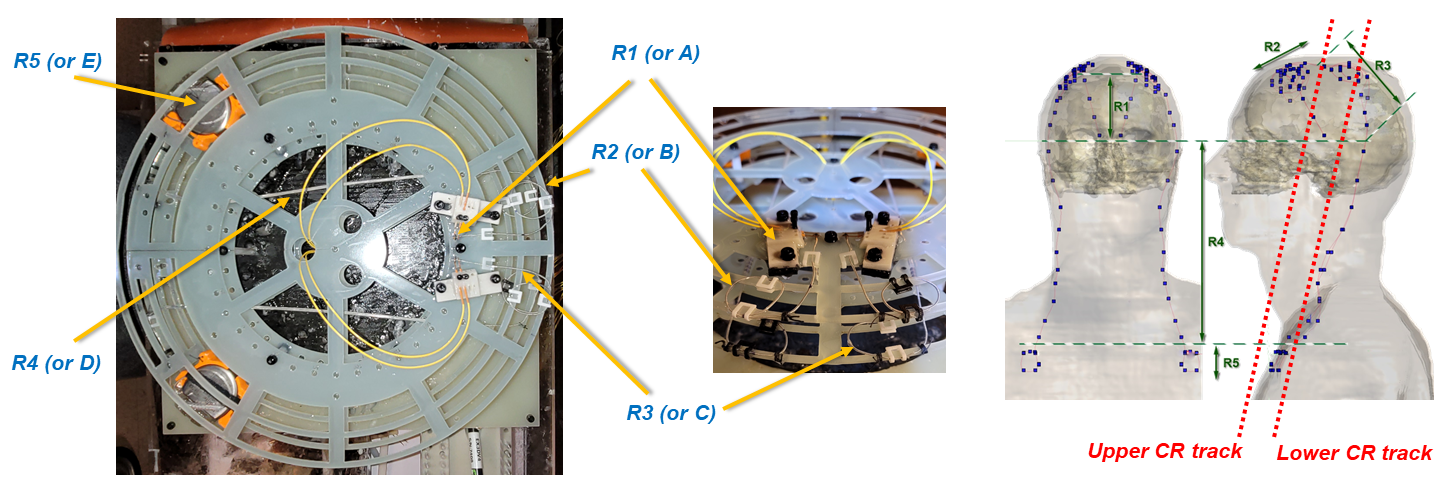
Figure 1: RIGHT: Model Duke, AP
& sagittal views of 2 DBS Ipsilateral Implants. We divide DBS trajectories
into 5 regions: R1: Inside brain, R2: Burr hole loops, R3: Parietal area with
relief loops, R4: Lead extension, & R5: IPG loops. LEFT: 2 Circular (CR) tracks,
3cm apart, are used to mount the 2 DBS Implants. One occupying one half of the
Upper CR track (R1+R2 of the trajectory) + the corresponding half of the Lower
CR track (R3+R4+R5 of the trajectory). And the 2nd implant occupying, in a
similar manner, the other halves of the Upper & Lower tracks.
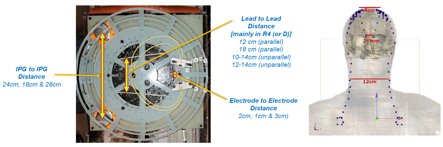
Figure 2: RIGHT: Model Duke
illustrating how human models were analyzed to characterize the distances
in-between the two DBS Ipsilateral implants. LEFT: The test setup described in
Figure 1 allowed setting the distances in-between the two DBS Ipsilateral implants
in a controlled manner. As shown, three distances, with variances derived from
human models, are explored: (1) Lead to Lead, (2) Electrode to Electrode, and
(3) IPG to IPG.
DOI: https://doi.org/10.58530/2023/2874