2870
A New Method to Improve RF Safety of Implantable Medical Devices using Inductive Coupling at 3.0T MRI1FDA, Silver Spring, MD, United States, 2Division of Biomedical Physics (DBP), FDA, Silver Spring, MD, United States, 3Division of Cellular and Gene Therapies (DCGT), FDA, Silver Spring, MD, United States
Synopsis
Keywords: Safety, Electromagnetic Tissue Properties
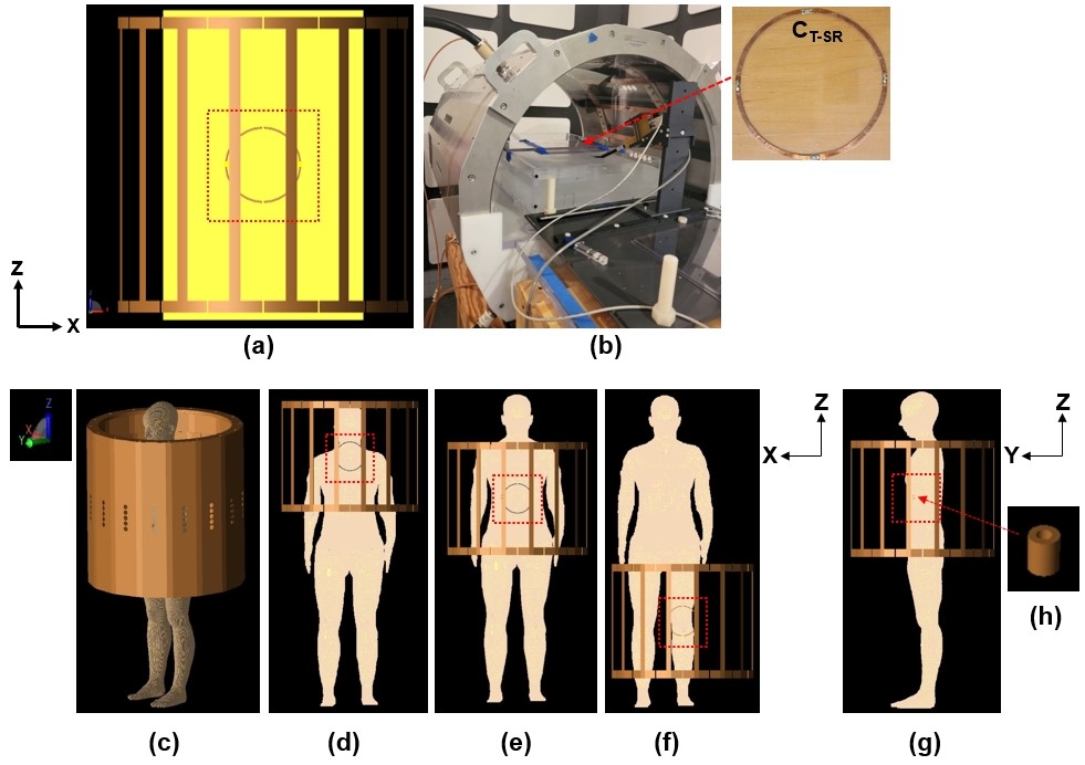
This study describes a new method to improve RF safety of implantable medical devices located outside of the imaging region by using a secondary resonator (SR) to reduce electric fields and corresponding specific absorption rate (SAR) during MRI. The SR is designed to produce opposing electro-magnetic fields (EM-fields) compared to the EM-fields made by a body coil at 3.0T. This study was performed using numerical simulations with ASTM phantom and human models, and corresponding experimental verifications with the ASTM phantom.
Keywords: RF safety, secondary resonator
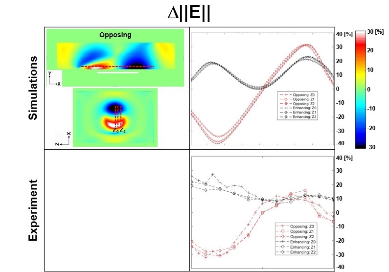
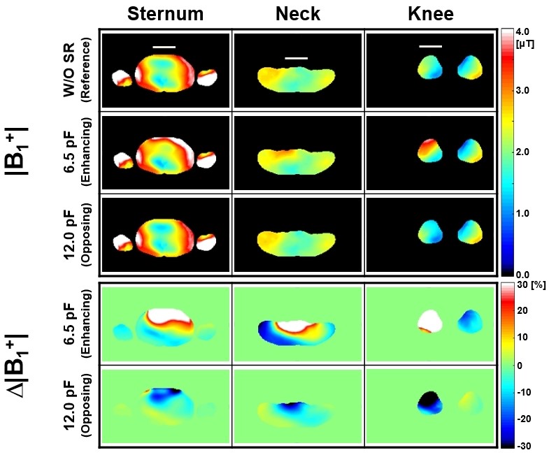
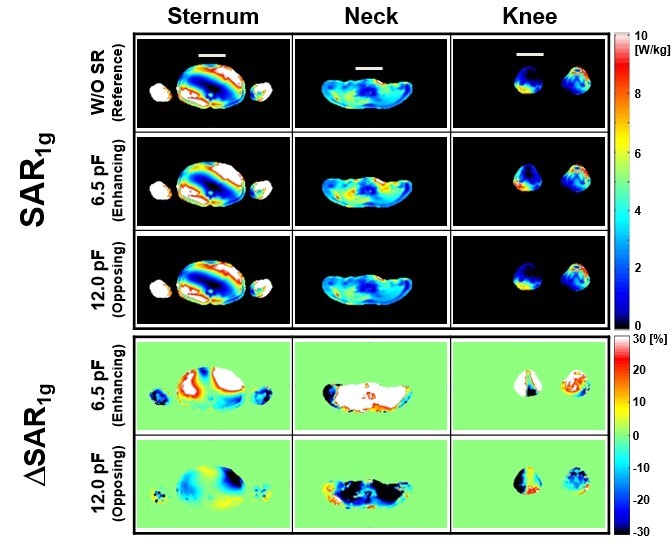
METHODS: This study was performed using numerical simulations with ASTM phantom and two adult human models of Ella and Duke, and corresponding experimental results using the ASTM phantom (Fig. 1). The first body coil (“610 mm body coil”) has an inner diameter (ID) of 610 mm, inner length (L) of 570 mm, outer length of 620 mm, width (W) of the copper strip for end ring and each rod of 25 mm, and an RF shield (ID = 660 mm, L = 1220 mm). Tuning capacitors (CT_Body) were placed in the end rings and had a value of 18.5 pF (Fig. 1 (a)). The circular SR was designed using parameters of ID = 150 mm, and W = 6 mm. The ASTM phantom was designed based on the ASTM standard test method and has parameters of L = 650 mm, W = 420 mm, and Height (H) = 90 mm with conductivity (s) = 0.47 S/m and relative permittivity (er) = 80. The experimental measurements were conducted using 3T MITS body coil (Zurich Med Tech, ID = 746 mm), EM field mapping probes (ER3DV6 and H3DV7), and ASTM phantom (Fig. 1 (b)). . RESULTS: Fig. 2 shows numerical simulation (a) and corresponding experimental results (b) of D||E|| without and with the SR of opposing (red lines) and enhancing (black lines) using ASTM phantom and body coil. Figures 3-4 show numerical simulation results of |B1+|, D|B1+| (Fig. 3), SAR1g, and DSAR1g (Fig. 4) within the Ella model at different landmark positions of Sternum (first column), Neck (second column) and Knee (third column) at 128 MHz. The effect of SR was shown more at Neck and Knee landmarks than that of Sternum landmarks, e.g., Mean D|B1+| were -8.09 % (Neck landmark), and -22.3% (Knee landmark), whereas -3.34% (Sternum landmark) with the SR making opposing magnetic fields.
DISCUSSION: The primary novelty of this study is that a new method using an SR designed to make opposing magnetic fields and lower SAR distributions has been proposed. The effect of SR was more obvious in the region having uniform and the same directional magnetic field components as the magnetic fields made by the SR, e.g., the central region of the body coil, because of fewer interactions with unwanted electromagnetic field components. Whereas the designed RF magnetic fields made by the SR were mainly BY in this study. Therefore, interactions with RF magnetic fields made by the SR and (BX, and BZ) made by the body coil would result in unwanted EM-field distributions. That would be the main reason that the effect of SR was not so obvious in some regions.
CONCLUSION: A new method using the designed SR making opposing magnetic fields to partially shield a sample has been proposed to improve RF safety at the VoI through numerical simulations with different simulation conditions at 3.0T.
Acknowledgements
No acknowledgement found.References
1. Medical electrical equipment - Part 2-33: Particular requirements for the basic safety and essential performance of magnetic resonance equipment for medical diagnosis, IEC60601-2-33, 2020
2. W. Mao, M. B. Smith, and C. M. Collins, "Exploring the Limits of RF Shimming for High-Field MRI of the Human Head," Magn Reson Med, vol. 56, pp. 918–922, 2006
3. H. Merkle et al., "Transmit B1-field correction at 7 T using actively tuned coupled inner elements.," Magn Reson Med, vol. 66, no. 3, pp. 901-10, 2011
4. L. Winter et al., "On the RF heating of coronary stents at 7.0 Tesla MRI," Magn Reson Med, vol. 74, 4, pp. 999-1010, 2015
Figures