2868
RF Safety Measurements of External Defibrillator Electrodes: E-Field and Temperature Mapping
Simon Reiss1, Ali Caglar Özen1, Thomas Lottner1, and Michael Bock1
1Division of Medical Physics, Department of Radiology, University Medical Center Freiburg, Freiburg, Germany
1Division of Medical Physics, Department of Radiology, University Medical Center Freiburg, Freiburg, Germany
Synopsis
Keywords: Safety, Safety
Currently, no external defibrillation system is available that is labeled MR safe. To create an MR safe device heating induced by the electrodes that are attached to the patient needs to be prevented. In this study, we propose a setup for high resolution RF E-field mapping of commercially available defibrillation electrodes and show that this setup can be used to precisely detect hot spots. At these hot spots, we then perform temperature measurements within a 1.5T to assess the MR safety of the electrodes.Introduction
Currently, no external cardiac defibrillator is clinically available for the use within the MRI environment which may lead to the exclusion of high-risk cardiac patients from an MRI exam. With an increasing number of MR-guided interventions, particularly electrophysiology procedures, also the necessity for cardiac monitoring and defibrillation in the MRI is evident. As current defibrillation system can only be used outside the MR room, patients still have to be carried out of the room before defibrillation. A recent study described a defibrillation system that was modified from a commercial system to be used inside the MR bore1. RF baluns were used to reduce RF coupling between the transmit coil and the long cable connecting the fibrillation unit to the electrodes. The cable is typically divided into a long stem cable which then connects to the disposable part, i.e., two separate cables that are attached to the electrodes. While modifying the stem cable seems unavoidable to create an MR safe defibrillation system, it would be desirable to use commercially available disposable electrodes. Even with a modified stem cable the residual RF coupling into the electrodes that are attached to the patient may lead to hazardous heating. In this study, we propose a setup for high resolution RF E-field mapping of commercially available defibrillation electrodes to detect hot spots. At these hot spots, we then perform temperature measurements within a 1.5T to assess the MR safety of the electrodes.Methods
Figure 1 shows a photograph of the E-field measurement setup based on an electro-optic E-field Sensor (EOS) with sub-millimeter resolution2–4. In this study, a 12 x 8 cm² large electrode with a 40 cm long cable was used. A container was 3D printed such that the electrode is positioned at the surface of the container over a cut-out. The cut-out is of the size of the conductive part of the electrode pad enabling direct contact between the electrode and the tissue mimicking liquid inside the container (here: water). The z-component of the E-field was mapped inside the liquid at a distance of 2 mm to the electrode surface (1 mm resolution in x- and y-direction). The electrode was excited via a toroidal current probe matched to fLarmor(1.5T) = 64 MHz surrounding the electrode cable. The measurement was performed with an empty and a water-filled container.After detection of the hot spots on the E-field map, temperature measurements were performed at a clinical 1.5 T system (Siemens Espree) using fiber-optical temperature probes (FOTPs, FOTEMP6-19, Optocon AG). The electrode was positioned on top of an agarose gel block (37 x 26 x 10 cm³) and 2 FOTPs were attached to the conducting side of the electrodes, i.e. at the surface between the electrode and the gel. Heating was induced for 6 minutes with a whole body SAR of 4 W/kg. Multiple positions of the electrodes and cables with respect to the body coil were tested until a maximum temperature increase (worst case) was found.
Results
Figure 2 shows the results of the E-field measurements via the magnitude and phase maps. The contour of the electrode is clearly visible as the E-fields is maximal at the edge of the electrode. In air, an additional edge is seen at the lower part of the electrode where the cable is attached and the conductive surface is covered by a non-conductive layer. In addition, the cable is seen as a local increase in the E-field which is not visible in water. The phase of Ez is homogeneous across the electrode indicating no dipole-like behavior. In water, the magnitude is reduced by 80 % compared to air. Figure 3 shows line profiles of Ez along the long axis of the electrode (here: y-direction), where the E field maximum are at the ends of the electrodes. The comparison between the field strength at the center line and the maximum projection across the x-direction further shows that the hot spots are the rounded edges of the electrode and not in the center.The temperature measurements at those hot spots resulted in a worst-case heating of 0.6 K and 0.5 K at the upper and lower edge of the electrode.
Discussion & Conclusion
This study presents for the first time high resolution E-field measurements of external defibrillator electrodes to detect hot spots. The setup that enables measurements under realistic loading conditions, i.e. within the tissue in close vicinity to the electrode with no boundary layer in-between. The measurements show that hot spots are located at the edges, particularly the rounded ones.Surface electrodes are typically exposed to two surrounding media: air and tissue. However, the cable connected to the electrode is fully in air where λ/2 is substantially longer than the electrode (2.3 m at 64 MHz). Thus, resonant coupling of the electrode is not expected. This is supported by the E-field measurements in air and water where the medium does not substantially influence the E-field pattern but only the magnitude. In conclusion, the presented E-field measurement setup enables a precise assessment of hot spots and can be a valuable tool for further comprehensive studies of the MR safety of external defibrillator electrodes.
Acknowledgements
This work was supported in parts by a grant from the German Federal Ministry for Economic Affairs and Energy (BMWi) under the grant program “Zentrales Innovationsprogramm Mittelstand (ZIM),” grant number KK5162802AJ1.References
1. Schmidt, E. J. et al. A Magnetic Resonance Imaging–Conditional External Cardiac Defibrillator for Resuscitation Within the Magnetic Resonance Imaging Scanner Bore. Circ. Cardiovasc. Imaging 9, e005091 (2016).
2. Reiss, S., Bitzer, A. & Bock, M. An optical setup for electric field measurements in MRI with high spatial resolution. Phys. Med. Biol. 60, 4355 (2015).
3. Reiss, S. et al. Analysis of the RF Excitation of Endovascular Stents in Small Gap and Overlap Scenarios Using an Electro-Optical E-field Sensor. IEEE Trans. Biomed. Eng. 68, 783–792 (2021).
4. Lottner, T., Reiss, S., Bitzer, A., Bock, M. & Caglar Özen, A. A Transfer Function Measurement Setup With an Electro-Optic Sensor for MR Safety Assessment in Cascaded Media. IEEE Trans. Electromagn. Compat. 63, 662–672 (2021).Figures
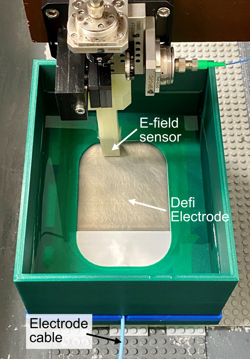
Photograph of the
E-field measurement setup.
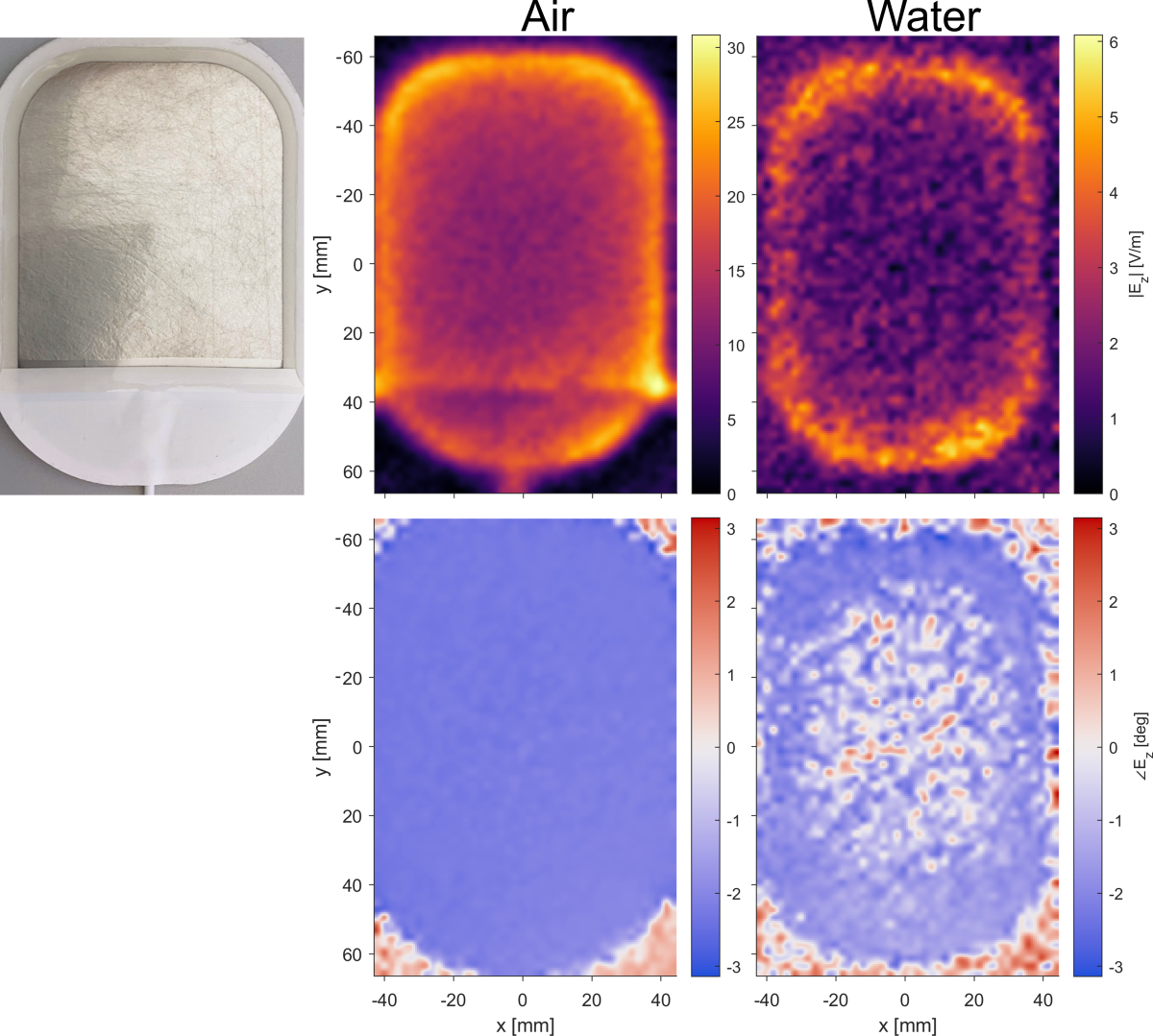
Results from the E-field measurements. The electrode was measured with the empty container (left) and with the container filled with water (right).
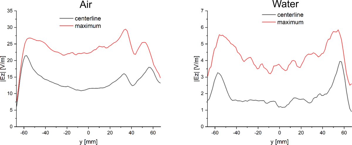
E-field along the y-direction (long axis) of the electrode for both measurements (air and water). The plot shows the E-field at the centerline of the electrode (x = 0) and a projection of the maximum value along the x-direction at each y-position.
DOI: https://doi.org/10.58530/2023/2868