2867
Comparison of the electric field and its line integral along the lead of a device across five different RF transmit coils1Department of Radiology, Mayo Clinic, Rochester, MN, United States, 2Mayo Clinic Graduate School of Biomedical Sciences, Rochester, MN, United States, 3GE Global Research, Niskayuna, NY, United States
Synopsis
Keywords: Safety, Safety
We introduce a method to calculate lead-tip voltage for implanted devices by considering 1) the individualized lead path extracted from X-ray-based images, 2) the incident electric field per unit B1+rms derived for the RF transmitter and a digital human body model, 3) the complex RF wavenumber in an insulated conductor derived from antenna theory. T/R coil transmitters in whole-body at 1.5T and 3.0T were considered, as well as a head coil on a compact 3T. Based on leads in 10 subjects, the results show the compact 3T produces less lead tip voltage than whole-body T/R coils.Introduction
The field strength of 3.0T has become the standard of care for brain MRI1 but it is not available for many patients with MR conditional implanted devices. Due to MR safety concerns, many implanted devices are conditioned to 1.5T. A high-performance, compact 3.0T (C3T) scanner2 was developed as a technology demonstrator. The C3T offers a unique solution to the unmet clinical need of brain imaging for patients with many implanted devices because the spatial extent of the RF, gradient, and main magnetic fields decrease rapidly caudal to the head3-6.A major safety concern of these implanted devices is device heating, especially lead-tip heating due to radiofrequency (RF) power deposition7-9. The line integral of the electric field along the implanted lead yields a voltage that determines lead tip heating. Previous work8 described a transfer function to calculate lead tip heating from a straight wire in a uniform electric field, and the method was further studied in Tokaya, et al.10.
In this work, we calculated lead tip voltages across five different RF transmission coils (whole-body 1.5T and 3.0T using a body coil and T/R head coil, and the C3T) using 1) the individualized lead path extracted from X-ray-based images; 2) the incident electric field per unit B1+rms derived11 for the five different RF transmitters, and a digital human body model; 3) the complex RF wavenumber in an insulated conductor derived from antenna theory.
Methods
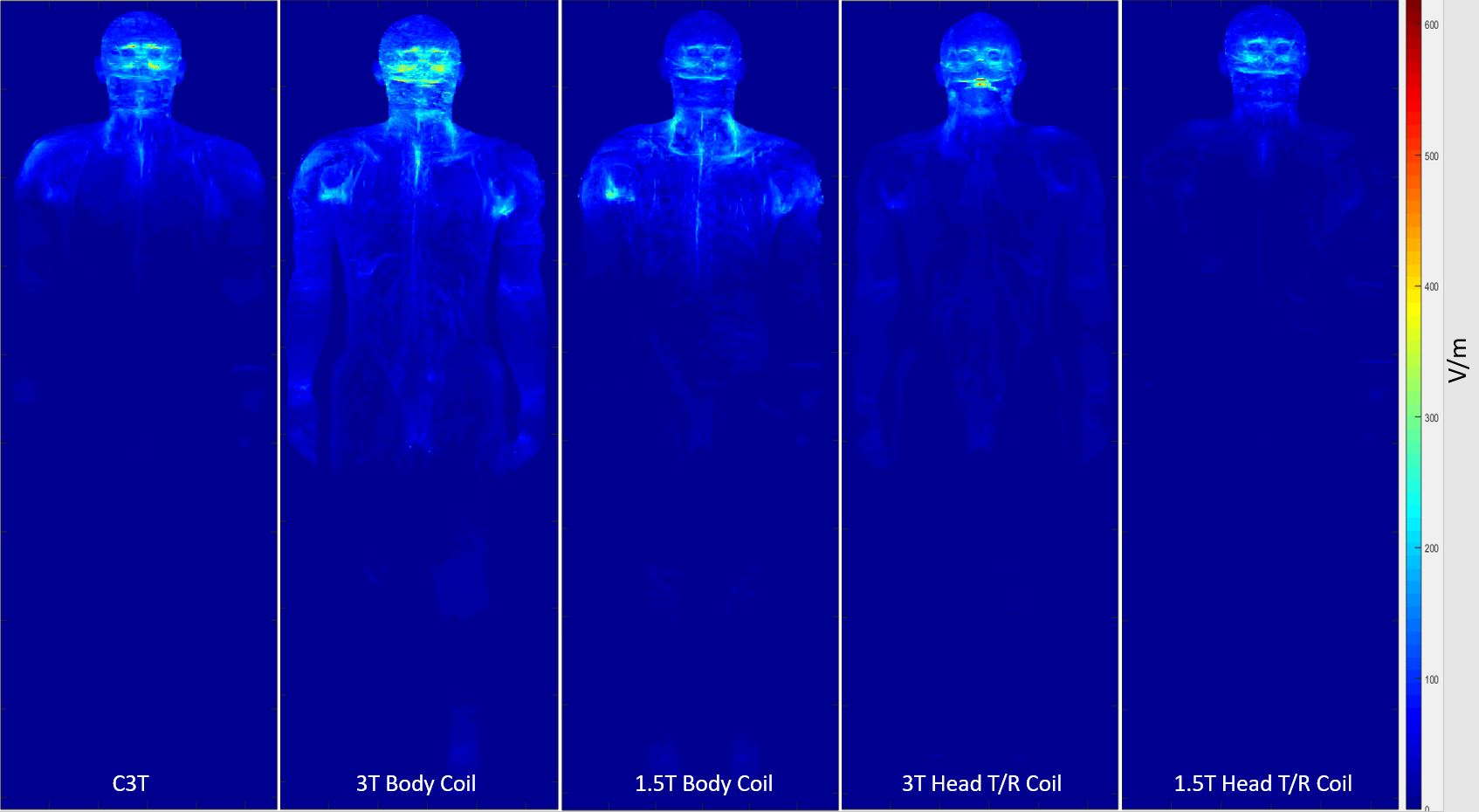
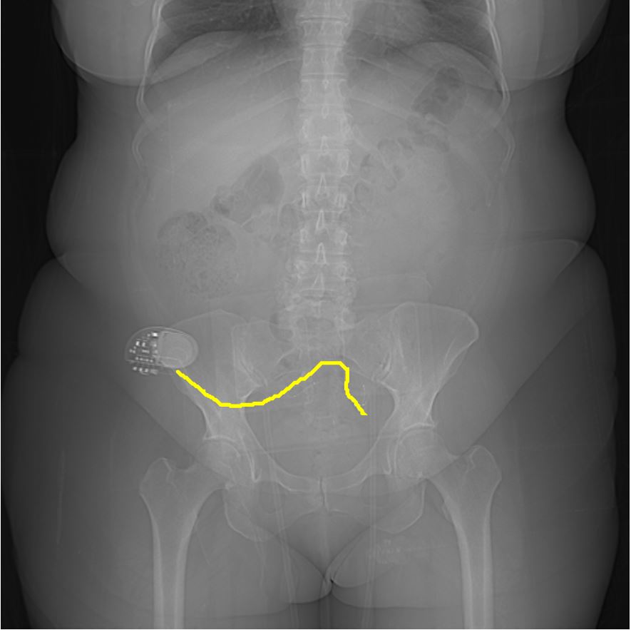
Previously, ten subjects have been scanned on the C3T under an IRB-approved protocol to compare the image quality with a whole-body 1.5T scanner12-13. Here, we extend that work by retrospectively studying lead placement for each device and calculating the line integral along the leads. Eight of the subjects had stimulators implanted in either the pelvis or abdomen, and two subjects had abandoned CIED leads—in locations where the electromagnetic fields of the C3T fall precipitously compared to whole-body MR.For each RF transmitter system, a digital human body model11, i.e., Duke (IT'IS Foundation, Zurich, Switzerland), was used to calculate the magnitude and phase of the electric field as shown in Figure 1. Similar to Golestanirad, et al.14, the individualized path of the lead for each implanted device was determined from X-ray images using the Livewire algorithm15, as shown in Figure 2. This path was superimposed on the appropriate electric field from Figure 1, which was further individualized by slight stretching or compression to account for patient height.
The lead tip voltage V is calculated by:
$$V=\int_{0}^{L}e^{ik_{c}l}\overrightarrow{E}\cdot d\overrightarrow{l}\tag{1}$$
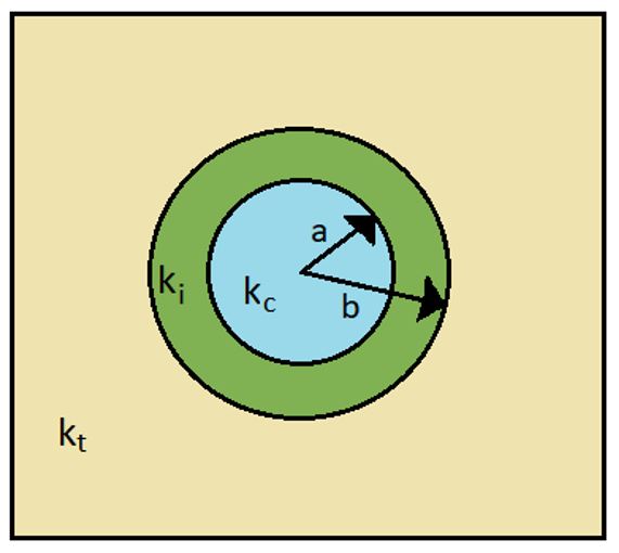
where $$$k_{c}$$$ is the complex wavenumber in the conductor, shown in Figure 3. $$$\overrightarrow{E}$$$ is the complex electric field for the specific field strength, RF transmitter and human body model, and the path, $$$\overrightarrow{l}$$$, is determined from X-ray-based data, where $$$\overrightarrow{l}=0$$$ corresponds to the lead tip.
From electromagnetic16 theory, the complex wavenumber in the tissue $$$k_{t}$$$ is given by:
$$Re(k_{t})=\omega\sqrt{\frac{\epsilon\mu}{2}}\left[ \sqrt{1+\left( \frac{\sigma}{\epsilon\omega} \right)^2}+1\right]^{1/2}, Im(k_{t})=\omega\sqrt{\frac{\epsilon\mu}{2}}\left[ \sqrt{1+\left( \frac{\sigma}{\epsilon\omega} \right)^2}-1\right]^{1/2} \tag{2}$$
where $$$\frac{\omega}{2\pi}$$$ is the Larmor frequency, $$$\mu$$$ is permeability ($$$\mu_{0}$$$ used here), and $$$\sigma$$$ and $$$\epsilon$$$ are conductivity and permittivity, respectively. The latter two depend on $$$\omega$$$, with spatial maps available from the digital human body model. With the exponential function in Eq. (1), the real part of $$$k_{c}$$$ accounts for half-wavelength effects, while the imaginary part of $$$k_{c}$$$ accounts for current losses from the conductor to the tissue. Because the insulating layer has $$$\sigma=0$$$, its wavenumber $$$k_{i}$$$ is real and reduces to $$$k_{i}=\omega\sqrt{\epsilon\mu}$$$. We assume $$$\epsilon=3\epsilon_{0}$$$ in the insulator, where $$$\epsilon_{0}$$$ is the permittivity of free space, as an estimate for silicone insulation.
From insulated antenna theory17, the complex wave number inside the conductor $$$k_{c}$$$ used in Eq. (1) can be derived from $$$k_{i}$$$ and $$$k_{t}$$$ and is given by:
$$k_{c}=k_{i}\left( 1+\frac{F(k_{t}b)}{ln(b/a)} \right)^{1/2}, F(z)=\frac{H_{0}^{\left( 1 \right)}(z)}{zH_{1}^{\left( 1 \right)}(z)} \tag{3}$$
where $$$H_{0}^{\left( 1 \right)}$$$ and $$$H_{1}^{\left( 1 \right)}$$$ are complex Hankel functions of the first kind. The complex voltage $$$V$$$ is obtained by substituting Eq. (3) into Eq. (1) and evaluating the line integral by discrete summation. We expect the lead tip heating to be proportional to the square of the calculated line integral $$$\left| V \right|^{2} $$$.
Results
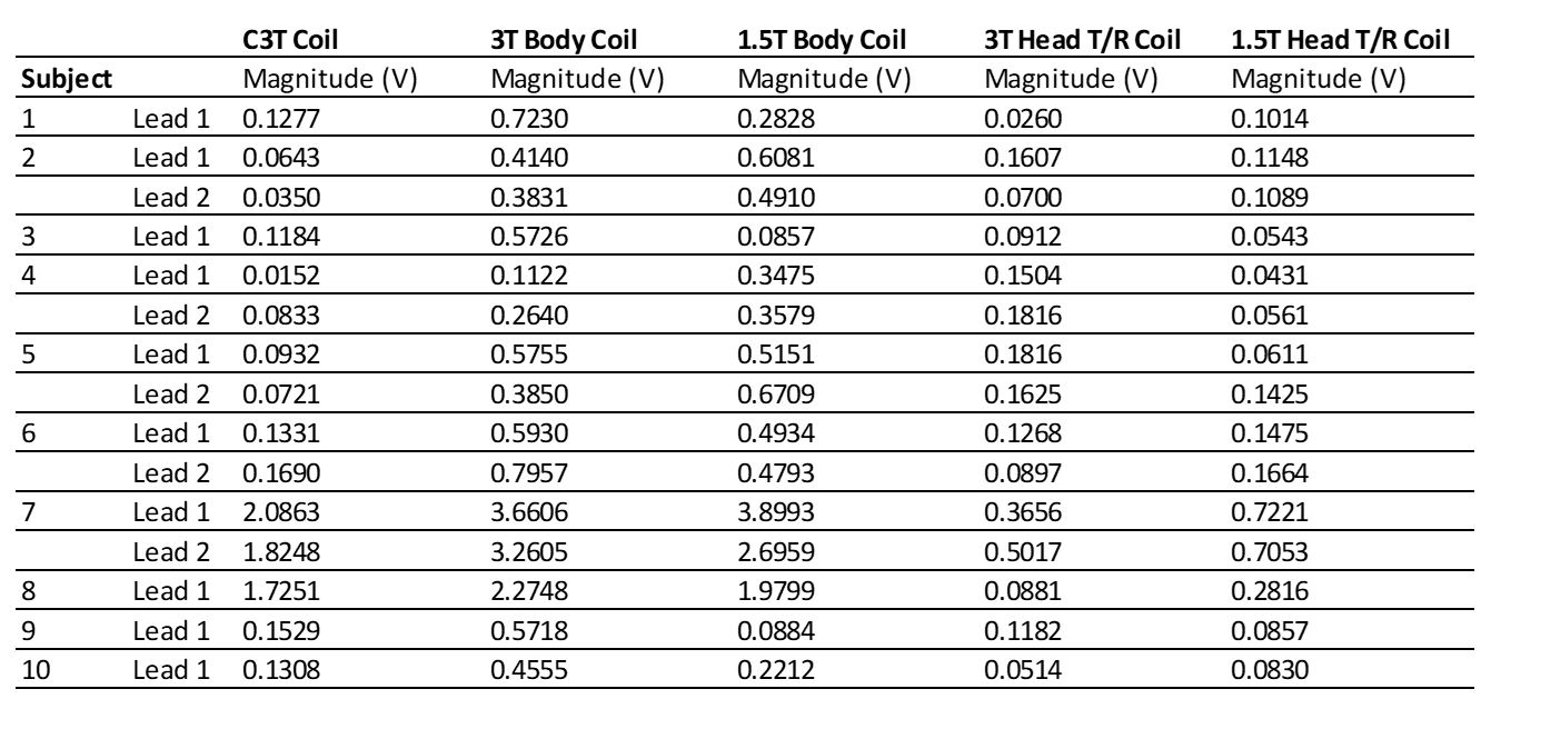
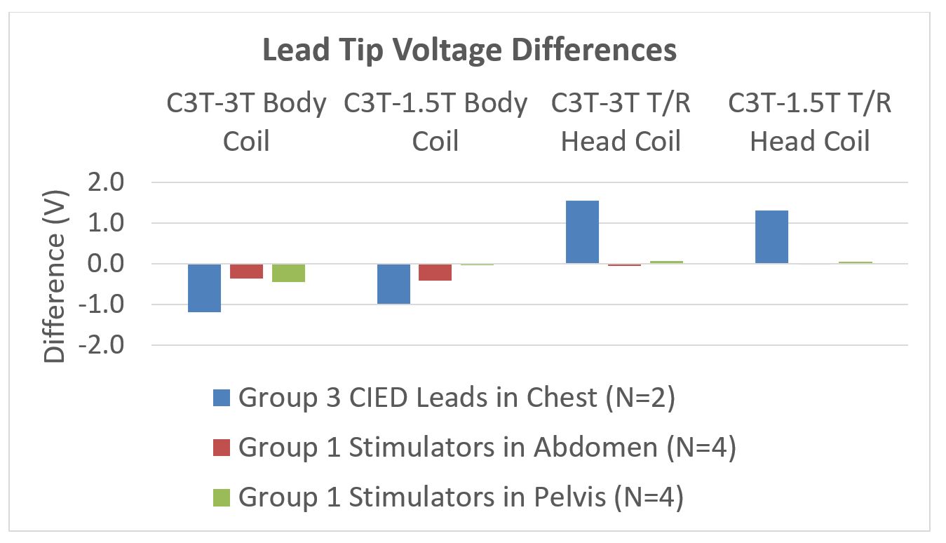
Figure 4 shows the magnitude of the calculated lead tip voltages for each subject. Figure 5 shows the comparison of the lead tip voltages of the 1.5T and 3T whole-body systems, each with RF body coil transmit or their individual T/R head coil, compared to the C3T.Discussion and Conclusion
The calculations suggest the C3T generates less lead tip heating than whole-body RF transmission at 1.5T or 3.0T, but greater than corresponding T/R head coils. To put the voltages in perspective, the same calculation for a ½ wavelength straight lead placed in the maximum $$$E$$$ field of the C3T yields >9V, which represents the worst-case scenario, far exceeding the values in Figure 4 or the plotted voltage differences in Figure 5. While T/R head coils produce lower lead tip voltages than the C3T, they also have reduced SNR and preclude parallel imaging, severely limiting image quality and prolonging scan time. This analysis supports the conclusion from12-13 that the C3T can provide high performance imaging while keeping the electromagnetic fields at acceptable levels at the location of the implanted device.Acknowledgements
This work was supported by NIH U01-EB024450. Special thanks to our MR Technologists Erin Gray, MS, MHA and Maria Halverson, RT(R)(MR).References
1. Alvarez-Linera J. 3T MRI: advances in brain imaging. Eur J Radiol. 2008 Sep;67(3):415-26. doi: 10.1016/j.ejrad.2008.02.045. Epub 2008 May 2. PMID: 18455895.
2. Foo TKF, Laskaris E, Vermilyea M, Xu M, Thompson P, Conte G, Van Epps C, Immer C, Lee SK, Tan ET, Graziani D, Mathieu JB, Hardy CJ, Schenck JF, Fiveland E, Stautner W, Ricci J, Piel J, Park K, Hua Y, Bai Y, Kagan A, Stanley D, Weavers PT, Gray E, Shu Y, Frick MA, Campeau NG, Trzasko J, Huston J 3rd, Bernstein MA. Lightweight, compact, and high-performance 3T MR system for imaging the brain and extremities. Magn Reson Med. 2018 Nov;80(5):2232-2245. doi: 10.1002/mrm.27175. Epub 2018 Mar 13. PMID: 29536587; PMCID: PMC6107412.
3. Shu Y, Tao S, Vermilyea M, Thomas KF Foo, Weavers PT, Trzasko JD, Huston J, Bernstein MA. Static magnetic field (B0) gradient evaluation of a compact 3T MR scanner. Proceedings of the 2017 International Society for Magnetic Resonance in Medicine Annual Meeting.
4. Shu Y, Meyer NK, Bardwell LJ, Tarasek M, Hua Y, Watson RE, Gorny KR, Felmlee JP, Edmonson HA, Foo TK, Bernstein MA. Compact 3T MRI for imaging patients with implanted devices: RF and SAR considerations. Proceedings of the 2019 International Society for Magnetic Resonance in Medicine Annual Meeting.
5. Bernstein MA, Edmonson HA, Hua Y, Watson RE, Huston J, Felmlee JP, Foo TK, Shu Y. Compact 3T MRI for imaging patients with implanted devices: Maximum gradient slew rate considerations. Proceedings of the 2019 International Society for Magnetic Resonance in Medicine Annual Meeting.
6. Bardwell Speltz L, Shu, Y In MH, M N, Gray E, Lanners D, Hua Y, Watson R, Huston III J, Foo T, Bernstein M. Compact 3T MRI for patients with implanted devices: Software tool to display MR fields at a specified location. Proceedings of the Virtual Meeting of the International Society for Magnetic Resonance in Medicine 2021; 2298.9.
7. Nyenhuis JA, Park SM, Kamondetdacha R, Amjad A, Shellock FG, Rezai AR, MRI and implanted medical devices: basic interactions with an emphasis on heating, IEEE Transactions on Device and Materials Reliability, vol. 5, no. 3, pp. 467-480, Sept. 2005, doi: 10.1109/TDMR.2005.859033.
8. Park SM, Kamondetdacha R, Nyenhuis JA. Calculation of MRI-induced heating of an implanted medical lead wire with an electric field transfer function. J Magn Reson Imaging. 2007 Nov;26(5):1278-85. doi: 10.1002/jmri.21159. PMID: 17969143.
9. Yeung CJ, Susil RC, Atalar E. RF safety of wires in interventional MRI: using a safety index. Magn Reson Med. 2002 Jan;47(1):187-93. doi: 10.1002/mrm.10037. PMID: 11754458.
10. Tokaya JP, Raaijmakers AJE, Luijten PR, Sbrizzi A, van den Berg CAT. MRI-based transfer function determination through the transfer matrix by jointly fitting the incident and scattered B1+ field. Magn Reson Med. 2020 Mar;83(3):1081-1095.
11. Tarasek MR, Shu Y, Kang D, Tao S, Gray E, Huston J 3rd, Hua Y, Yeo DTB, Bernstein MA, Foo TK. Average SAR prediction, validation, and evaluation for a compact MR scanner head-sized RF coil. Magn Reson Imaging. 2022 Jan;85:168-176. doi: 10.1016/j.mri.2021.10.011. Epub 2021 Oct 16. PMID: 34666159.
12. Bardwell Speltz L, Shu Y, Watson R, Trzasko J, Gray E, Halverson M, Arant J, Huston III J, Foo T, Bernstein M. Compact 3T brain MRI for patients with abandoned leads of cardiac implantable electronic devices. Proceedings of the International Society for Magnetic Resonance in Medicine 2022; 5266.
13. Bardwell Speltz L, Shu Y, Watson R, Trzasko J, Gray E, Halverson M, Huston III J, Lee SK, Tarasek M, Foo T, Bernstein M. Evaluation of a compact 3T MRI scanner for patients with MR conditional implanted devices. Proceedings of the International Society for Magnetic Resonance in Medicine Workshop on MR Safety 2022; 4
14. Golestanirad L, Kirsch J, Bonmassar G, Downs S, Elahi B, Martin A, Iacono MI, Angelone LM, Keil B, Wald LL, Pilitsis J. RF-induced heating in tissue near bilateral DBS implants during MRI at 1.5 T and 3T: The role of surgical lead management. Neuroimage. 2019 Jan 1;184:566-576. doi: 10.1016/j.neuroimage.2018.09.034.
15. 2013, Christian Wuerslin, University of Tuebingen and University of Stuttgart, Germany
16. Reitz FJ, Milford JR, Christy RD. Foundations of Electromagnetic Theory, 4th Edition. 2003. Addison-Wesley.
17. King RW, Lee KM, Mishra SR, Smith GS. Insulated linear antenna: Theory and experiment. Journal of Applied Physics. 1974 Apr;45(4):1688-97.
Figures