2866
New System, New Approach: Fasten up transfer function validation measurements, prove of concept
Finya Ketelsen1,2 and Gregor Schaefers1,3
1MRI-STaR - Magnetic Resonance Institute for Safety, Technology and Research GmbH, Gelsenkirchen, Germany, 2TU Dortmund University, Dortmund, Germany, 3MR:comp GmbH, Testing Service for MR Safety & Compatibility, Gelsenkirchen, Germany
1MRI-STaR - Magnetic Resonance Institute for Safety, Technology and Research GmbH, Gelsenkirchen, Germany, 2TU Dortmund University, Dortmund, Germany, 3MR:comp GmbH, Testing Service for MR Safety & Compatibility, Gelsenkirchen, Germany
Synopsis
Keywords: Safety, Safety, Implants, RF-induced heating
The novel open 64 MHz linear exposure system offers new possibilities for the test process of active implants for RF-induced heating as a safety issue. This study proves the concept, that the measurements for the validation process of the transfer function, which models the electric behavior of an active implant, could be accelerated from hours of precise work to minutes without any rearranging. Because the system is open, there is significantly more space than in a birdcage coil and the object and measuring probe can be mounted to a movement system, that can access the whole phantom.Introduction
RF-induced heating is a major safety issue for patients with active implantable medical devices (AIMDs) during an MRI examination. The current test procedures for AIMDs with application leads are described in the ISO/TS 10974 clause 8 tier 31, where their characteristics are described through a lead electrical model, so called transfer function. This function must be validated and can then be used to calculate the AIMDs temperature increase for any given electrical field at or along the implant location inside the human body. The open 64MHz linear exposure system offers new possibilities to accelerate the validation measurements and decreases placement uncertainties compared to a standard birdcage coil.Methods
To validate the transfer function, the AIMD should be exposed to varies tangential electrical fields. The temperature rise should be measured for each exposure condition and compared to the model prediction. The different tangential electric field exposures shall vary in magnitude and phase and ensure a wide dynamic range in temperature rise1.The ISO/TS 109741 provides a set of routings and phantoms inside the birdcage coil, including the time-consuming preparation of routings, which is necessary for each single measurement.
With the open 64MHz linear exposure system, introduced in2, it is possible to mount the AIMD and measurement probe to a movement system. The AIMD is shaped as desired and moved through the phantom to vary the exposure conditions. In addition, the field conditions at each position can be further varied by different phase settings between the two channels.
Depending on the probe type a considerable number of measurements can be achieved in minutes. Another advantage is that the probe placement relative to the AIMD is fixed for all measurements, so that the probe placement does not add up to the measurement uncertainty.
To prove this concept a 35 mm insulated wire (one open and one insulated end) was used. The wire was shaped as an U and the open end was fixed to an E-field probe (SAR Probe, EX3DV4, SPEAG) and attached to an in-house movement system. The measuring path is shown in Figure 1 in blue. The phantom was filled with saline solution (σ=0.47 S/m, ɛr=78). With continuous movement the E-field probe measured 957 positions in about 30 min per phase setting.
In a second setup, the same measurements for less positions were down with a temperature probe (Optocon) to verify the E-field measurement.
The temperature measurement was done in saline solution and gel (σ=0.47 S/m, ɛr=78) and took 30 s per position. Three different phase setting where used (0°,90°,180°) and eleven positions per phase setting (total duration 1:10 h). The measuring path for this is shown in Figure 1 in orange.
The E-field distribution was simulated in Ansys HFSS and previously validated in2. The tangential component along the U-shaped test object was extracted from the numerical predictions for each position and phase setting.
Results
The magnitude and phase of the tangential electrical field for nine exemplary exposure conditions from the three phase settings are shown in Figure 2. Magnitude and phase ramps, linear phase and phase reversal fields are included in the 33 exposure conditions.Figure 3 shows the correlation between the temperature rise in saline solution versus the temperature rise in gel. The dynamic range in temperature rise over the 33 exposure conditions is 0.1-4.6°C for saline solution and 0.1-11.1°C in gel for 30 seconds measurement.
In Figure 4 the correlation between the squared E-field measurements and temperature rise measurements is shown.
Discussion
Figure 2 shows, that the open 64 MHz linear exposure system is able to produce a set of independent tangential field distributions along the U-shaped test object. Magnitude and phase ramps, linear phase and phase reversal fields are included. All positions inside the phantom could be accessed without rearranging the test object or probe.Furthermore, it is shows that there is a linear correlation between the temperature rise in gel and saline solution and a linear correlation between the squared E-Field and the temperature rise. Therefore in this case it is possible to use the E-Field probe for the transfer function validation measurement.
In this configuration, there were 957 test object positions on the blue grid in Figure 1 reachable in about 30 minutes for one phase setting.
Even though, there are a lot of dependent tangential electric field distributions among these 957 positions, the concept seems to be suitable, and the grid can be adapted to the field distribution for each phase setting.
Conclusion
This study shows that the open linear exposure system is sufficient for the transfer function validation process. On one hand it produces varies E-field conditions and on the other hand opens the possibility to measure about 1000 positions in 30 min, which can be configurated to any desired number and duration. Without rearranging the test object or probe every position inside the ASTM phantom is accessible .The correlation between the squared E-field measurement and the temperature rise in gel and saline solution is linear the therefore a scaling factor, that is added in the validation process.
This concept will be further investigated for different objects and routings and will be compared to the model predictions.
Acknowledgements
No acknowledgement found.References
1. Technical specification ISO/TS 10974:2018, “Assessment of the safety of magnetic resonance imaging for patients with an active implantable medical device,” The International Organization for Standardization, 2018.
2. F. Ketelsen, K. Kröninger, G. Schaefers, „Validation of a new 64MHz RF exposure system for testing medical implants for RF-induced heating according to ASTM-F2182 and ISO/TS 10974”, Proc. Intl. Soc. Mag. Reson. Med. 29, 2021
Figures
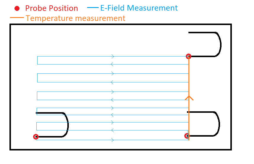
This figure shows the U-shaped wire inside the
ASTM phantom, the probe position is marked in red and the measuring path for
the E-field und temperature measurement in blue and orange.
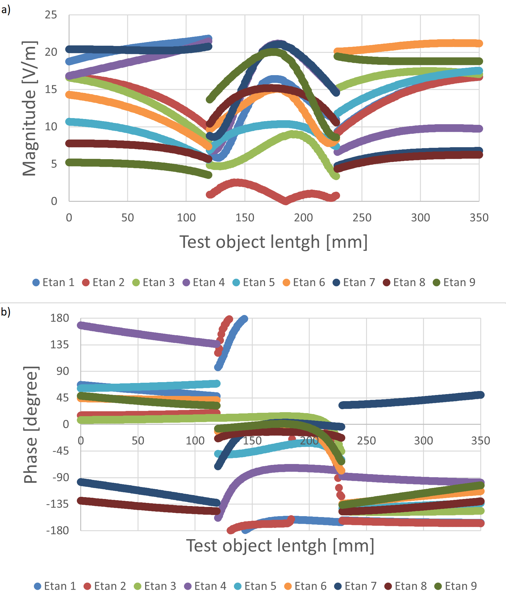
Figure 2 shows the a) the Magnitude and b) the Phase
of Etan along the Test Object for nine exposure conditions
exemplary.
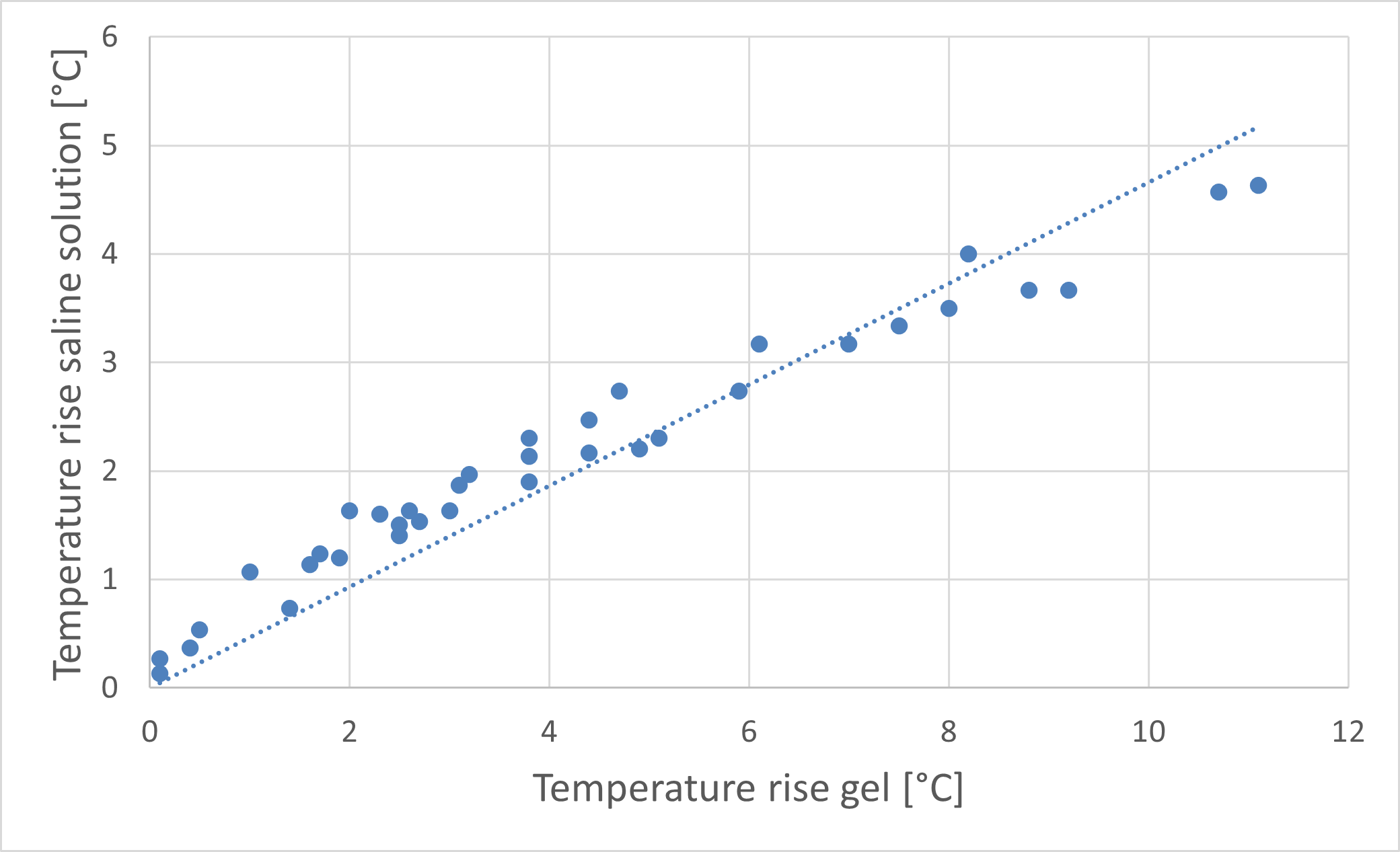
Figure 3 shows the correlation between the temperature
rise in saline solution and gel.
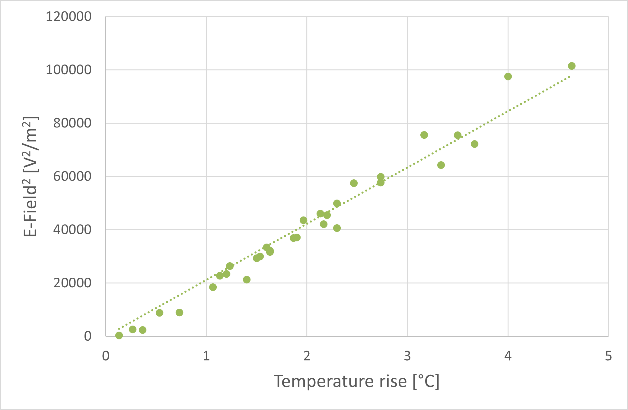
Figure 4 shows the correlation between the squared E-Field and temperature rise is saline solution.
DOI: https://doi.org/10.58530/2023/2866