2865
Is MR-induced RF heating around implanted leads lower at 0.55 T than 1.5 T? Not necessarily.1Department of Radiology, Feinberg School of Medicine, Northwestern University, Chicago, IL, United States, 2Department of Biomedical Engineering, McCormick School of Engineering, Northwestern University, Evanston, IL, United States
Synopsis
Keywords: Low-Field MRI, Low-Field MRI, Simulations
Low-field MRI systems have been advertised as “safe” for patients with implants – but is this true? In a series of systematic simulations, we looked at implants with varied length, amount of coiling, and insulation during RF exposure in both 0.55 T and 1.5 T MRI environments. We found that both the actual and apparent length of the implant can significantly impact heating. There are several cases where heating is substantially higher at 0.55 T than 1.5 T, suggesting that no broad claims should be made, and these factors need to be carefully considered before scanning a patient.Introduction
Low-field MRI systems are currently attractive alternatives to standard field MRI as they are generally lower in cost and easier to site1,2. Due to technological advancements, the image quality of low-field systems has also improved greatly3. But is low-field MRI “implant-friendly”? It is true that the specific absorption rate (SAR) of radiofrequency energy tends to be lower at lower field strengths2, and reduced metal artifacts have been observed at lower-field strengths as well4,5. However, although SAR tends to be lower at lower field strengths in the absence of implants, excessive heating can occur in the presence of elongated leads (such as those in cardiac or deep brain stimulation devices) due to the antenna effect6,7. Safe scans of patients with implants at low-field MRI have been performed8, but more quantitative data needs to be available before such broad claims are made. This study aims to explore how different variables impact implant heating in both 0.55 T and 1.5 T MRI environments.Methods
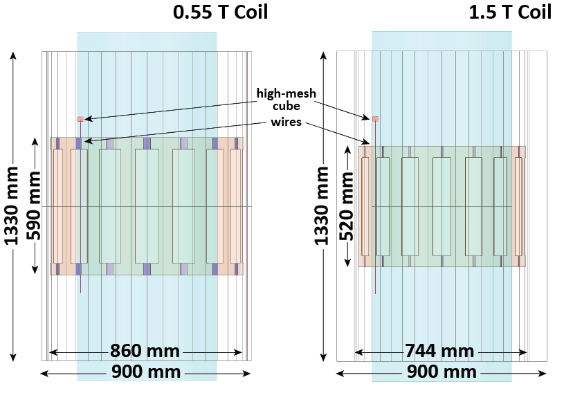
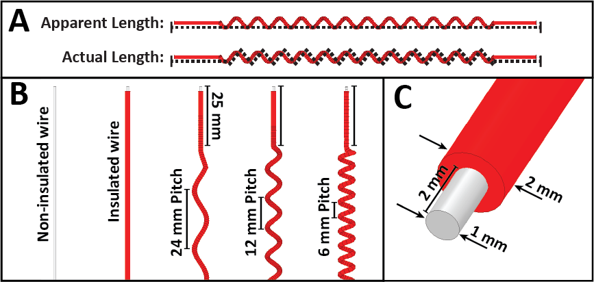
A total of 368 simulations were performed. Electromagnetic Simulations were implemented in ANSYS Electronic Desktop 2021 R1 (ANSYS, Canonsburg, PA). Two 16-rung, high-pass, birdcage body coil models were created and tuned to 0.55 T (23 MHz) and 1.5 T (63.6 MHz). Coil geometries were based off the Siemens Aera Coil and Siemens FreeMax Coil, respectively (Figure 1). Models of insulated wires were created with apparent lengths from 10 cm to 120 cm at 5 cm intervals (i.e., 23 different apparent lengths). For each apparent length, wires were created as straight and in three different helical pitches, representing different actual lengths. Each wire was simulated (a) as an uninsulated 1 mm diameter wire made from Platinum-Iridium (σ = 4 x 10⁶ Sm-1 , εr = 1) and (b) as an insulated wire surrounded by a 0.5 mm thick urethane insulation (σ = 0 Sm-1, εr = 3.5) and a 2 mm exposed tip (Figure 2). The wires were placed inside a cylindrical phantom (150 cm tall, 60 cm diameter) with properties of average tissue (σ = 0.5 Sm-1, εr = 64). They were centered on the central axial plane, 15 mm from the edge of the cylinder. The maximum 0.1g-averaged SAR (MaxSAR) was calculated in a high-mesh 20 mm x 20 mm x 20 mm cube centered at the tip of the lead for each simulation, and the input power was adjusted to have a mean B1+ of 5 µT on a central axial plane passing through the isocenter of the coil.Results
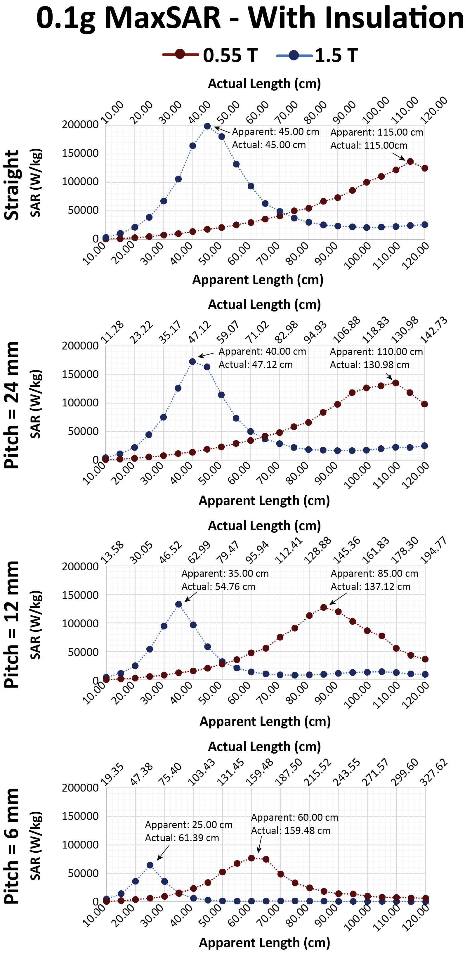
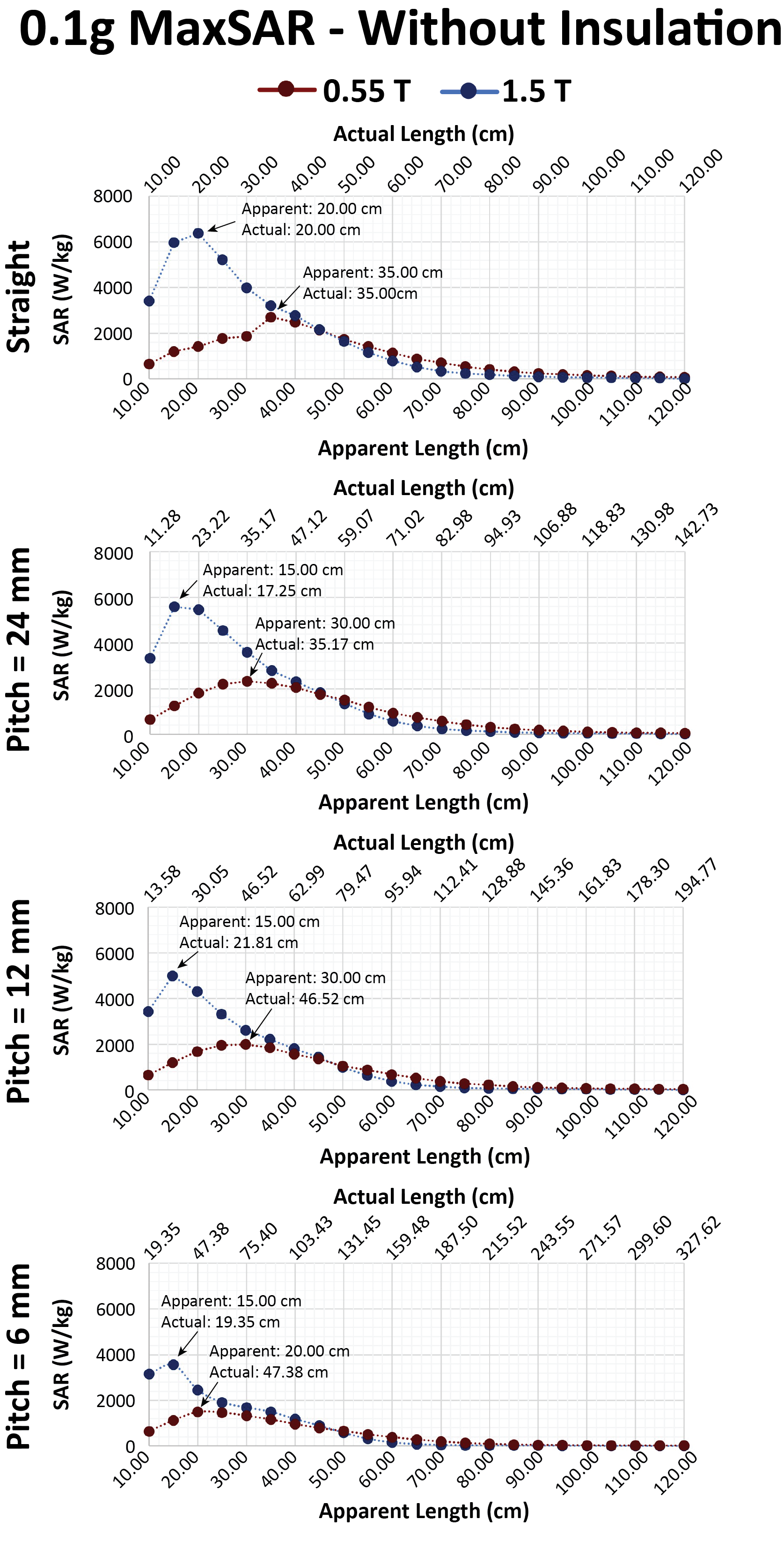
For a straight implant with insulation, the peak MaxSAR occurred at an actual length of ~115 cm at 0.55 T and ~45 cm at 1.5 T (Figure 3). For both MRI systems, as the pitch decreased and the helices became tighter, the apparent length at which the resonance occurred (i.e., length at which the MaxSAR peaked) and the magnitude of the MaxSAR decreased, however, the actual length of the wire at which resonance occurred increased. The implants without insulation generated significantly less heating than the implants with insulation. The length at which the peak MaxSAR occurred also substantially decreased for leads without insulation, especially at 0.55 T (Figure 4).Discussion
The resonance effect can be observed in elongated implants in an MRI environment. The commonly accepted rule of thumb is that the heating is at a maximum when the implant length is close to the half-wavelength of the RF field produced by the coil in the tissue9, however, real implants behave in a more complex manner. We observed that the presence of insulation as well as the inductive coupling from the loops formed by the helices further modulate the resonant length and the peak MaxSAR in helical wires10. In our phantom with εr = 64, the half-wavelength of RF field at 1.5 T was 29.5 cm in the gel, and the resonant lengths of bare and insulated wires were ~20 cm and ~45 cm, respectively. For an insulated wire, making a helical structure out of the straight wire substantially changed the actual length at which resonance occurred (from 45 cm to 60 cm) whereas such modulation was not observed for the bare wire whose resonant length remained close to 20 cm. A similar trend was observed at 0.55 T.In practice, most conductive implants have an outer layer of insulation to protect the integrity of the wire in the environment of the body, and they also have a helical internal structure to increase mechanical stability. In such cases, high heating could occur at low-fields even when the apparent length of the implant is much shorter than the wavelength. This can prove hazardous in patients with elongated implants of 60 centimeters or more which often have internal geometries that make the actual length much longer.
Conclusion
This simulation study serves as a simple demonstration that 0.55 T scanners are not necessarily always safer than 1.5 T scanners and looks at how inductive coupling and the presence and absence of insulation impacts resonant heating. All factors must be carefully considered when making decisions about patient scans.Acknowledgements
This work has been supported by NIH grant R03EB033864.References
[1] M. Sarracanie and N. Salameh, “Low-Field MRI: How Low Can We Go? A Fresh View on an Old Debate,” Front. Phys., vol. 8, p. 172, Jun. 2020, doi: 10.3389/fphy.2020.00172.
[2] J. P. Marques, F. F. J. Simonis, and A. G. Webb, “Low‐field MRI: An MR physics perspective,” J. Magn. Reson. Imaging, vol. 49, no. 6, pp. 1528–1542, Jun. 2019, doi: 10.1002/jmri.26637.
[3] N. Koonjoo, B. Zhu, G. C. Bagnall, D. Bhutto, and M. S. Rosen, “Boosting the signal-to-noise of low-field MRI with deep learning image reconstruction,” Sci. Rep., vol. 11, no. 1, p. 8248, Dec. 2021, doi: 10.1038/s41598-021-87482-7.
[4] I. Khodarahmi et al., “New-Generation Low-Field Magnetic Resonance Imaging of Hip Arthroplasty Implants Using Slice Encoding for Metal Artifact Correction: First In Vitro Experience at 0.55 T and Comparison With 1.5 T,” Invest. Radiol., vol. 57, no. 8, pp. 517–526, Aug. 2022, doi: 10.1097/RLI.0000000000000866.
[5] F. F. Schröder et al., “Low-field magnetic resonance imaging offers potential for measuring tibial component migration,” J. Exp. Orthop., vol. 5, no. 1, p. 4, Dec. 2018, doi: 10.1186/s40634-017-0116-2.
[6] L. Golestanirad et al., “RF heating of deep brain stimulation implants in open‐bore vertical MRI systems: A simulation study with realistic device configurations,” Magn. Reson. Med., vol. 83, no. 6, pp. 2284–2292, Jun. 2020, doi: 10.1002/mrm.28049.
[7] L. Golestanirad et al., “RF-induced heating in tissue near bilateral DBS implants during MRI at 1.5 T and 3T: The role of surgical lead management,” NeuroImage, vol. 184, pp. 566–576, Jan. 2019, doi: 10.1016/j.neuroimage.2018.09.034.
[8] C. Schukro and S. B. Puchner, “Safety and efficiency of low-field magnetic resonance imaging in patients with cardiac rhythm management devices,” Eur. J. Radiol., vol. 118, pp. 96–100, Sep. 2019, doi: 10.1016/j.ejrad.2019.07.005.
[9] B. Bhusal, P. Bhattacharyya, T. Baig, S. Jones, and M. Martens, “Measurements and simulation of RF heating of implanted stereo-electroencephalography electrodes during MR scans,” Magn. Reson. Med., vol. 80, no. 4, pp. 1676–1685, Oct. 2018, doi: 10.1002/mrm.27144.
[10] P. A. Bottomley, A. Kumar, W. A. Edelstein, J. M. Allen, and P. V. Karmarkar, “Designing passive MRI-safe implantable conducting leads with electrodes: The design of MRI-safe implantable leads,” Med. Phys., vol. 37, no. 7Part1, pp. 3828–3843, Jun. 2010, doi: 10.1118/1.3439590.
Figures