2704
Numerical Simulation of SAR for a dual-frequency 1H/19F Body Coil array at 3 Tesla1Imaging Centre of Excellence, University of Glasgow, Glasgow, United Kingdom, 2NHS Greater Glasgow & Clyde, Glasgow, United Kingdom, 3Siemens Healthcare Limited, Frimley, United Kingdom, 4Aurum Biosciences Limited, Glasgow, United Kingdom, 5MR CoilTech Limited, Glasgow, United Kingdom
Synopsis
Keywords: RF Arrays & Systems, Shims
An eight-channel transceiver 1H/19F dual-frequency 3-Tesla body array has been developed to investigate the use of a perfluorocarbon (PFC) compound for use in as diagnostic tool in the investigation of inflammation inside the human body. Dual-frequency operation enables the same coil to be used at both frequencies, which reduces scan time, improves patient comfort, and provides accurate anatomic localisation. This RF coil consists of 8 transceiver elements, with four in each posterior and anterior half. This abstract presents the electromagnetic (EM) simulations for B1+ homogenisation, SAR assessment and validation of the dual-frequency array.
Introduction
To investigate the use of a perfluorocarbon (PFC) for use in as diagnostic tool in the investigation of inflammation inside the human body, an eight-channel transceiver 1H/19F dual-frequency 3-Tesla body array has been developed. The switching between the two frequencies is enabled by the control signals that are programmed through the coil file. The dual-frequency operation enables the same coil to be used at both frequencies, which reduces scan time, improves patient comfort, and provides accurate anatomic localization.The array consisted of four transceiver elements each on the anterior and posterior halves. A 1x2 power splitter is used to feed the RF power from the scanner to the two halves and the power is split further within each half using a 1x4 splitter. The transmit phase between the coil element input and power splitter is controlled by coaxial cable lengths to homogenize the B1+ field1.
This abstract presents the electromagnetic (EM) simulations for B1+ homogenization, SAR assessment and validation of the dual-frequency array.
Methods
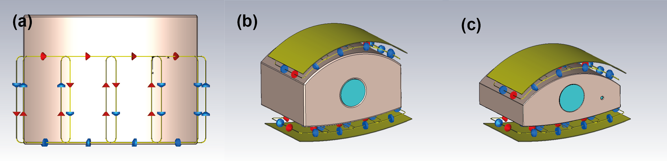
EM simulation of the radio-frequency (RF) coil was performed using CST Studio Suite 2021 (Dassault Systems, France). The simulations were performed at both 1H and 19F frequencies (123.2 MHz and 115.9 MHz). The 3D model of the array is shown in Figure 1. The coil is locally shielded and extended 200mm along the z-direction. The adjacent array elements are overlapped and the coupling between the next-neighbouring elements are decoupled using transformers2. The model included all component losses, scanner bore and cable loss.For validation, a large and small phantom (300mm long, 400mm wide, height: 250mm and 200mm) were modelled3 to mimic different loading conditions and filled with tissue equivalent solution (electrical conductivity 0.46 S/m, permittivity 60.8). Each has a 100mm diameter void, which can be filled with the same solution or with the PFC compound ABL-1014. The EM model of the coil and the phantoms are shown in Figure 1.
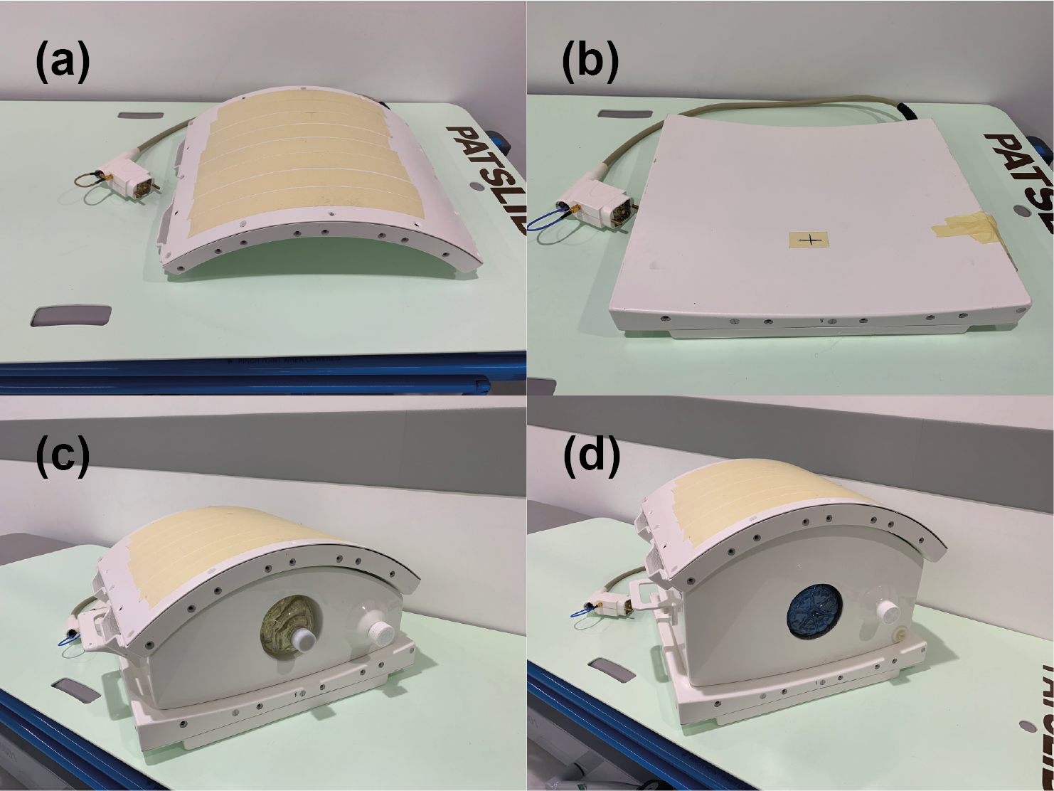
The coil was tuned and matched to the Duke body model5. Single channel B1+ field maps were extracted to calculate the phase shims required to generate the preferred B1+ distribution. The optimisation criteria included the mean reference voltage, local 10g SAR, SAR efficiency and B1+ homogeneity for a region of interest covering the central mass of the Duke torso. A shortlist of phase shims was created and further human body simulations using both Duke and Ella body models was carried out to validate each shim. From these results a final shim was selected and the cable phases on the coil was adjusted accordingly. A photograph of the coil and the two phantoms are shown in Figure 2.
Experimental validation of the B1 maps was performed in the small and large body phantoms in a 3T MRI system (MAGNETOM Prisma, Siemens Healthineers Germany). B1+ maps were acquired using a pre-saturated TurboFLASH sequence6 (TR 5000 ms, TE 1.83 ms, flip angle 8 degrees, resolution 7mm*7mm, matrix 64*64, FoV 450*450, slice thickness 8mm).
To demonstrate the image quality at 1H and 19F frequencies, the small body phantom filled with tissue-equivalent solution with the ABL101 insert in the center was imaged using a gradient echo sequence at 1H frequency (TR 100ms, TE 10ms, flip angle 25 degrees, matrix 128*128, FOV 450 *450mm, slice thickness 5mm, 1 average,) and a gradient echo sequence at 19F frequency (TR 100ms, TE 3.3ms, flip angle 25 degrees, matrix 128*128, FOV 450mm*450mm, slice thickness 5mm, 10 averages).
Results
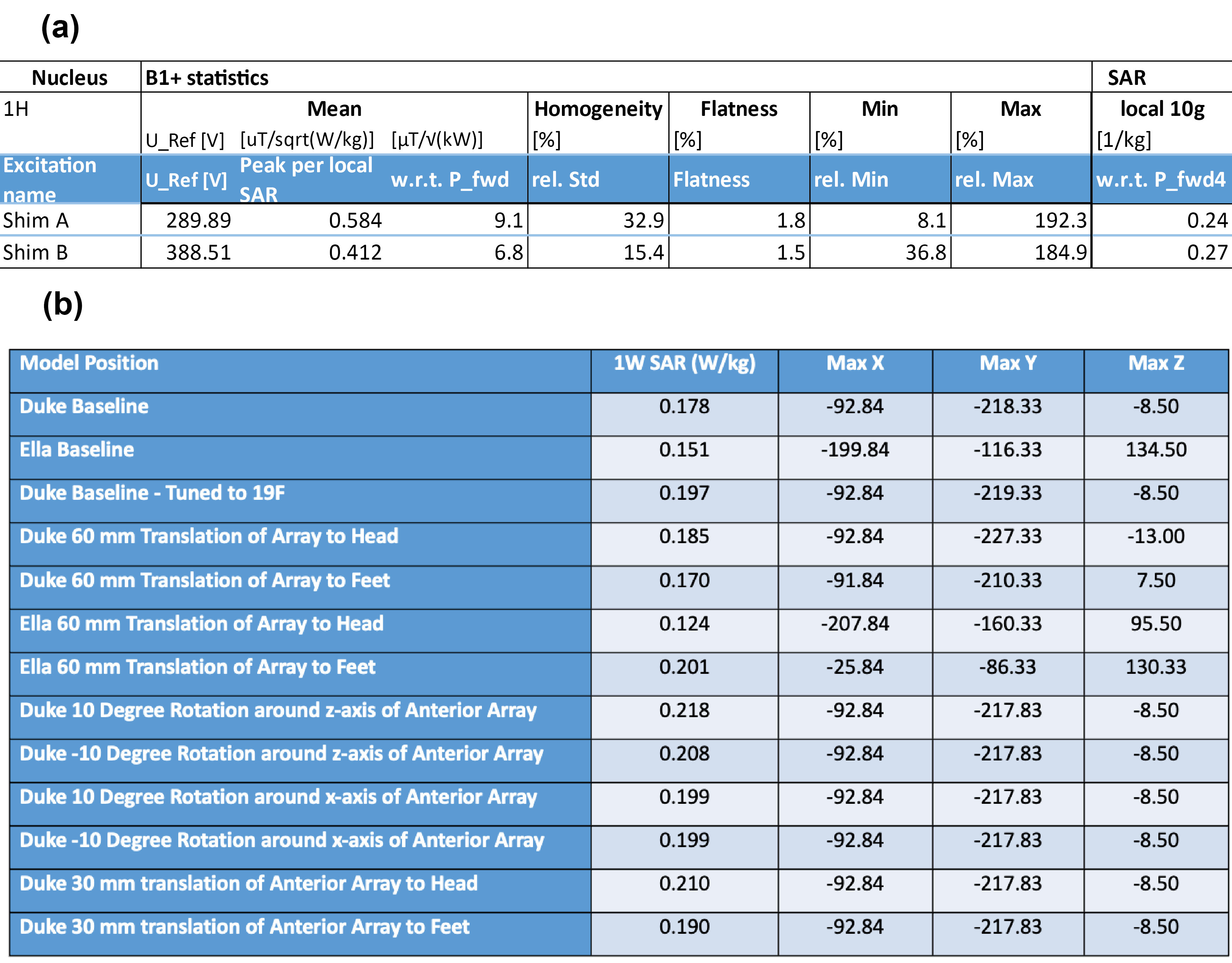
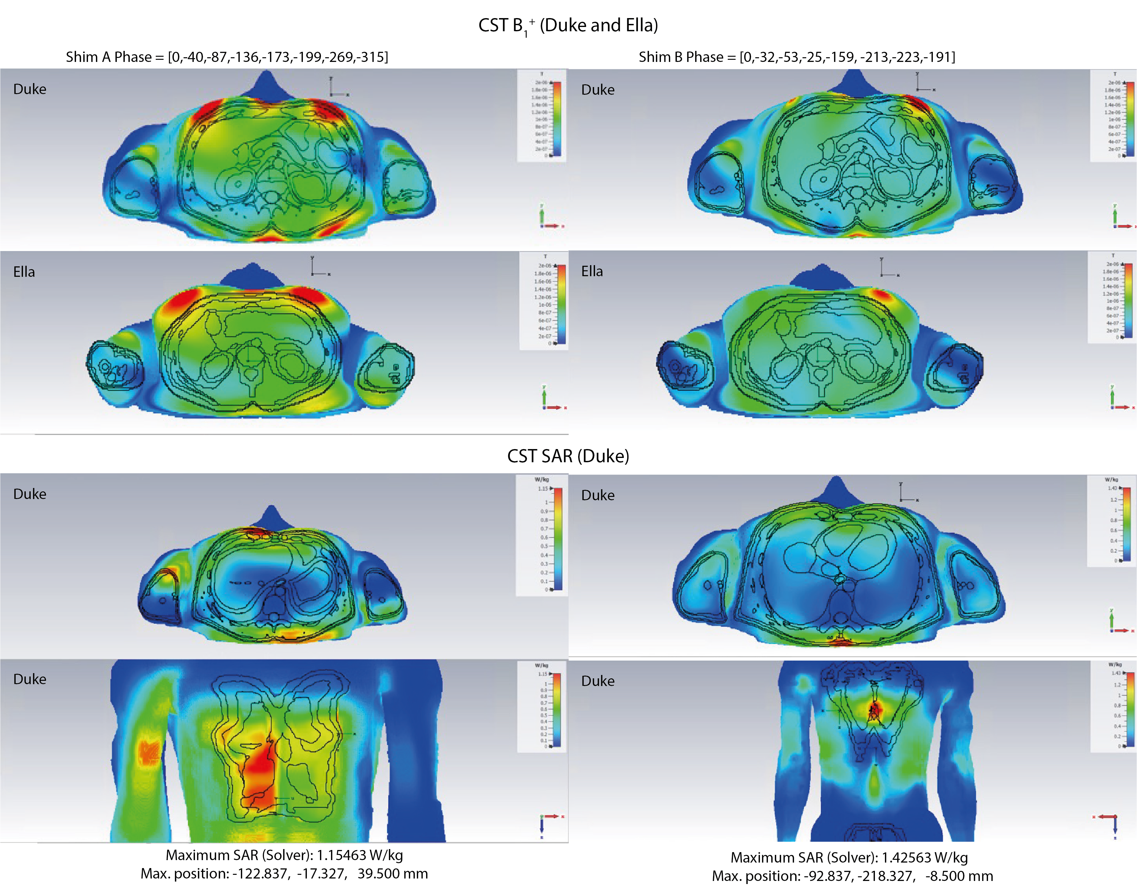
The B1 and SAR characteristics for two optimised shim solutions (Shim A and Shim B) are shown in Figure 3(a). Shim A gives the most SAR efficient B1 excitation (largest Peak B1 per local SAR). Shim B gives the most homogeneous B1 across the Duke model (smallest relative standard deviation for homogeneity).Figure 4 demonstrates the comparison between these two shim solutions for B1+ in Duke and Ella, and the SAR map at the peak SAR position in the Duke model. Shim B was implemented in the coil. The peak local SAR obtained from simulations of Duke and Ella at a range of different positions is shown in Figure 3(b).
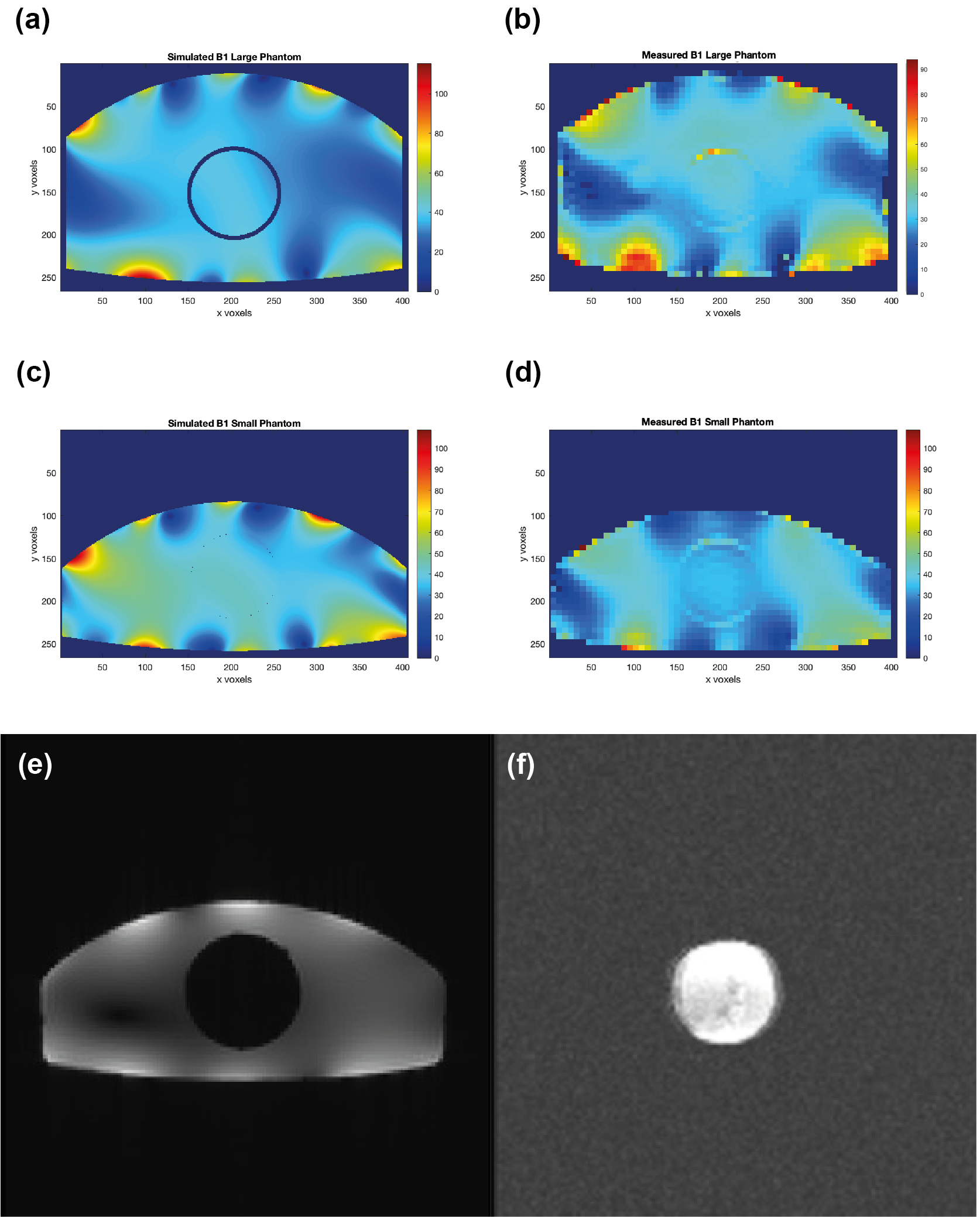
A comparison of the measured and simulated B1 maps is shown in Figure 5(a) and (b) for the large body phantom at 1H frequency, and in Figure 5(c) and (d) for the small body phantom. Figure 5 (e) and (f) show the gradient echo images of the small body phantom filled with tissue-equivalent solution with the ABL-101 insert in the centre, acquired at 1H frequency (e) and at 19F frequency (f). In the 19F image the ABL-101 phantom is shown clearly, with no visible signal from the surrounding 1H phantom.
Conclusion
We chose the phase shim with minimum standard deviation for its more desirable coverage of both the liver and the spleen, since in this case the benefit is greater than the loss due to higher SAR. For the eight-channel transceiver 1H/19F dual-frequency 3-Tesla body array, B1 simulations were performed at both frequencies and experimentally validated at 1H frequency. Simulation and measurement shows the robustness of the single phase shim solution. This works across a range of body models and positions and is experimentally validated in two phantoms.Acknowledgements
Wellcome, Innovator Award 222695/Z/21/Z "Development of in-vivo 19F Clinical MR imaging Using a Novel 19F/1H Coil in Combination with an Intravenous Perfluorocarbon (ABL-101)"References
1. Adriany G, Van de Moortele PF, Wiesinger F, et al. Transmit and receive transmission line arrays for 7 Tesla parallel imaging. Magn Reson Med. 2005;53(2):434-445. doi:10.1002/mrm.20321.
2. Williams SN, Allwood-Spiers S, McElhinney P, et al. A nested eight-channel transmit array with open-face concept for human brain imaging at 7 tesla. Front Phys. Jul 2021. Vol 9.
3. Hoffmann J, Shajan G, Scheffler K, Pohmann R. Numerical and experimental evaluation of RF shimming in the human brain at 9.4 T using a dual-row transmit array. MAGMA. 2014 Oct;27(5):373-86. doi: 10.1007/s10334-013-0419-y. Epub 2013 Nov 26. PMID: 24276542.
4. Darçot E, Colotti R, Brennan Det al. A characterization of ABL-101 as a potential tracer for clinical fluorine-19 MRI. NMR Biomed. 2020;33(1):e4212. doi:10.1002/nbm.4212
5. Christ A, Kainz W, Hahn EG, et al. The Virtual Family--development of surface-based anatomical models of two adults and two children for dosimetric simulations. Phys Med Biol. 2010;55(2):N23-N38. doi:10.1088/0031-9155/55/2/N01
6. Chung S, Kim D, Breton E, Axel L. Rapid B1+ mapping using a preconditioning RF pulse with TurboFLASH readout. Magn Reson Med. 2010;64(2):439-446. doi:10.1002/mrm.
Figures