2703
Numerical Evaluation of Specific Absorption Rate of Local Transceiver Coil Arrays for Ultra-High Field MRI with Different Local Mesh Properties1High-field Magnetic Resonance, Max Planck Institute for Biological Cybernetics, Tuebingen, Germany, 2Max Planck Institute for Biological Cybernetics, Tuebingen, Germany, 3Department for Biomedical Magnetic Resonance, University of Tübingen, Tübingen, Germany
Synopsis
Keywords: High-Field MRI, Safety
Home-built RF UHF MRI coils have to be carefully evaluated for safety issues. This is performed by simulating the coil model, which often include thin conductors, loaded by a human voxel model. Currently such models are available mainly for time-domain solvers. Fine mesh over conductors and the large voxel model may lead to time-consuming simulations. Therefore, for smaller head-sized coils, the model has to be cut and the proper mesh size chosen. In this work, we numerically investigated the dependence of B1+ and SAR for four different head coils on fine local meshing and the size of the voxel model.Introduction
Ultra-high field (UHF, 7T and above) MR imaging is an extensively developing field. Recently two commercial 7T MRI scanner were cleared for limited clinical use. For imaging at such high field strengths, strong inhomogeneity occurs due to the fact of the wavelength shortening inside the human body. This also greatly increases local tissue heating usually evaluated by calculating a specific absorption rate (SAR). Therefore, home-built RF coils are always to be carefully verified for safety issues 1. This is commonly done by simulating the accurate model of the coil loaded by a realistic human model. Currently, such models are available mainly for time-domain solvers. Since experimental verification of simulated SAR is not feasible, the modeling must be carefully validated, which also includes the evaluation of all potential sources of errors.Commonly elements of RF coils (arrays), i.e. loops, dipoles, are constructed using thin conductors, e.g. strips or wires, (1.5-mm wire 2,3), one needs to apply a high density of computational mesh to acquire correct port impedances, current density, and consequently correct field distribution. In addition, the presence of the full-body voxel model makes the total simulation model very large. These may lead to unreasonably time-consuming simulations. Therefore, the choice of the mesh size and proper cutting of the voxel models for simulations of smaller RF coils, e.g. head size, become an important problem. In this work, we numerically evaluated the dependences of impedances, RF field, and peak SAR for several RF array models on the property of the local mesh and voxel model size.
Methods
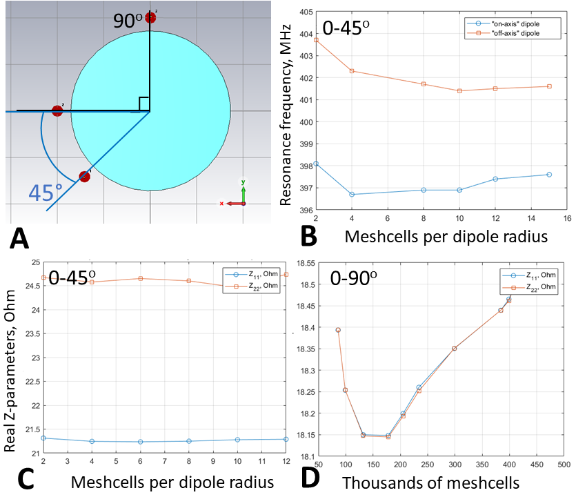
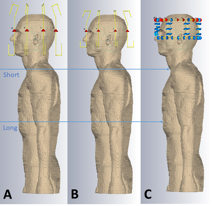
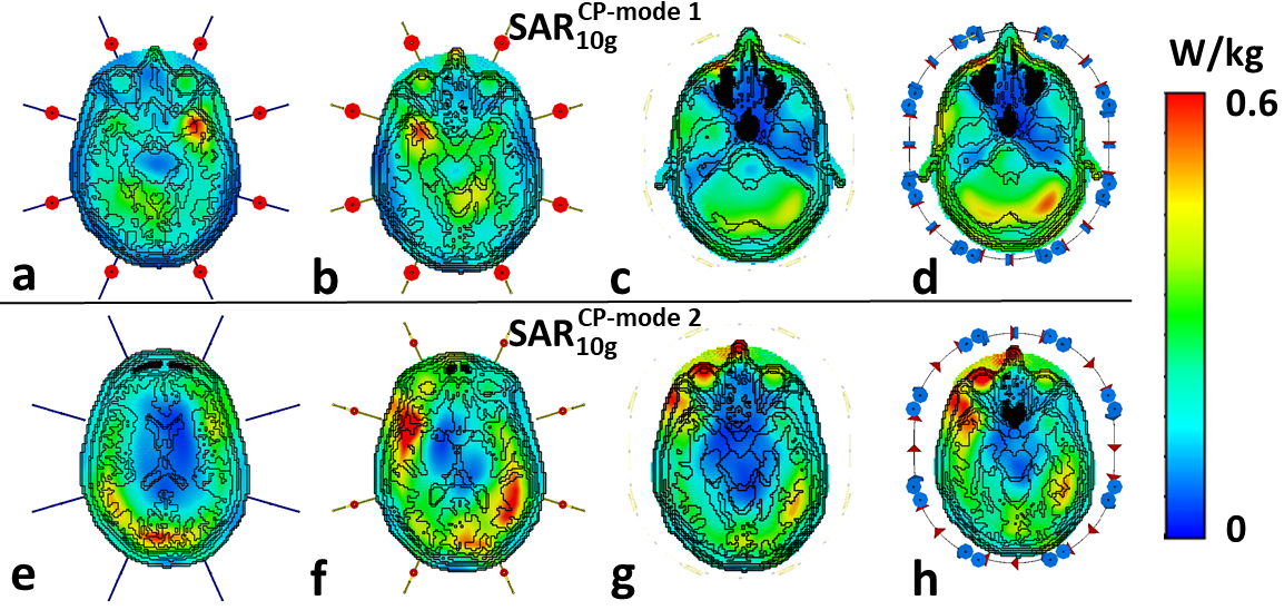
Firstly, we evaluated the effect of the amount of mesh cells per cross-section of a coil’s conductor on Z-parameters (i.e. coil impedance). For that, a pair of 21-cm straight dipoles loaded by a homogeneous (εr=58.3, σ=0.64 S/m 3) cylindrical phantom of 170-mm in diameter and 200-mm in length was simulated with CST Studio Suite 2021, using time-domain solver. The dipoles were separated by 45-(Fig.1A) and 90-degree angles and computed with different local mesh densities: 2, 4, 8, 10, 12, and 14 mesh cells per cross-section. Then, we simulated an 8-element 400-MHz folded-end dipoles array 1 using four sizes of local mesh cells, i.e. 0.5, 0.7, 1, and 2-mm. In these simulations, we evaluated pSAR10g (peak local SAR averaged over 10g of tissue) and B1+ for the most common two CP-modes, excited by the progressive phase shift feed of -45 (CP1) and -90 (CP2) degrees.Finally, we evaluated the effect of the voxel model size on SAR and B1+ values. In these simulations, we used the “Duke” voxel model cut at three different lengths, i.e. short, long, and extra-long (Fig.2). pSAR10g and ‹B1+› (averaged over 13-cm transversal slab) were numerically calculated for four eight-element arrays shown in Fig.2, i.e. 300-MHz folded-end dipole array 2, 400-MHz folded-end dipole array 4, and two (300 and 400-MHz) almost identical in geometry loop arrays 5.
Results
It is shown in Fig.1 (B, C), that the resonant frequency of the same equally tuned dipoles shows a shift, if one dipole is placed on the axis, and the second one is rotated by 45 degrees. This effect could be compared with Fig.1 (D), where the dipoles are placed directly on the x and y axes with the subsequent global mesh refinement.Next, different local mesh sizes for the shortest voxel model were computed 0.5, 0.7, 1, and 2-mm. Table 1 shows a small deviation between the conventional local voxel size of 0.7-mm. Table 1 also shows no specific correlation between the total amount of mesh cells, which depends mostly on the voxel model’s length. Simulated B1+ for both CP-modes and every model shown in Fig.3 (a-h). Fig.4 (a-h) depicts SAR maps, excited by the CP-modes.
Discussion and conclusion
Simulation results of two dipole and phantom models using a time-domain solver (Fig. 1 B, C) shows a stable shift of the dipole's impedance. However, since each coil will be tuned and matched, such impedance changes are not critical but can lead to an unrequired phase shift for the signal. The pSAR evaluated for different local mesh properties deviates weakly even with the voxel model's wrong size (i.e., cropped at the neck). ‹B1+› deviates less than 1% for each local mesh size.In this work, we demonstrated numerically how simulation parameters change with the voxel model size and local mesh properties. Despite a slight variation in dipole impedance with local mesh properties discovered, the mesh or voxel model size did not significantly change ‹B1+› and SAR estimates. pSAR was expected to increase with the shortening of absorbing tissue due to the higher power deposition, but simulations did not prove it. Furthermore, the pSAR simulation results appeared to be stable enough.
Acknowledgements
No acknowledgement found.References
1. Hoffmann J, Henning A, Giapitzakis IA, Scheffler K, Shajan G, Pohmann R, Avdievich NI. Safety testing and operational procedures for self-developed radiofrequency coils. NMR Biomed 2016;29(9):1131-1144.
2. Avdievich, N.I., Solomakha, G., Ruhm, L., Nikulin, A.V., Magill, A.W. and Scheffler, K., 2021. Folded‐end dipole transceiver array for human whole‐brain imaging at 7 T. NMR in Biomedicine, 34(8), p.e4541.’
3. Shajan G, Kozlov M, Hoffmann J, Turner R, Scheffler K, and Pohmann R. A 16-channel dual-row transmit array in combination with a 31-element receive array for human brain imaging at 9.4 T. Magn Reson Med 2014;71:870–879.
4. Avdievich NI, Solomakha G, Ruhm L, Henning A, Scheffler K. Unshielded bent folded-end dipole 9.4 T human head transceiver array decoupled using modified passive dipoles. Magn Reson Med 2021;86(1):581-597.
5. Avdievich NI, Giapitzakis IA, Pfrommer A, Henning A. Decoupling of a tight-fit transceiver phased array for human brain imaging at 9.4T: Loop overlapping rediscovered. Magn Reson Med 2018;79(2):1200-1211.
Figures