2696
Temperature rise modelling framework for multiple electrode configurations on parallel transmit systems.1Cleveland Clinic, Cleveland, OH, United States
Synopsis
Keywords: Safety, Safety
Implanted electrodes can induce unsafe heating during MRI. Developing safe MRI protocols can be a burdensome process, involving intensive simulations that are hard to tailor to individual patients. To increase the feasibility of safe imaging of patients with implanted electrodes, we extend previous work, that nulled induced currents when the number of transmitters exceeded the number of electrodes, to account for the case when these are equal or the number of electrodes exceeds the number of transmitters. In such cases, complete nulling (no measured temperature rise) is impossible in all electrodes unless an acceptable induced temperature rise is allowed.Introduction
Patients with implanted electrodes are typically denied the potential benefit of HF (>3T) or UHF MRI (>7T) due to safety concerns 1. Higher field strengths provide increased signal-to-noise ratio (SNR) 2, which allows for smaller structures to be more clearly visualized. To increase the feasibility of safe imaging of patients with implanted electrodes, Eryaman et al. 3 and Sadeghi-Tarakameh et al. 4 demonstrated a method to identify a safe operating point—an implant-friendly (IF) mode 5,6. The results of 3,4 were extended to the case of bilateral electrodes 7. Here, we extend the formalism presented by Sadeghi-Tarakameh et al. 7 to an arbitrary number of electrodes and validate the formalism with a phantom experiment.Theory
The case of two electrodes and two transmitters is important because bilateral electrodes are common for treating movement disorders 8, and two transmitters are common among standard body transmit coils.$$ A_1 I_{1,1} + A_2 I_{1,2} = J_1 $$
$$ \qquad \qquad \quad \qquad \qquad \quad \qquad \qquad \qquad A_1 I_{2,1} + A_2 I_{2,2} = J_2
\qquad \qquad \qquad \qquad \qquad \qquad \quad \qquad (1) $$
$$$ A_i $$$ is the complex amplitude in transmitter . $$$ I_{j,i} $$$ is the current induced in electrode $$$ j $$$ when transmitter $$$ i $$$ is switched on and includes contributions from the transmitter and the other electrode. $$$ J_j $$$ is the net current induced in electrode $$$ j $$$.
Various studies report a linear relationship between the specific absorption rate (SAR) and measured temperature rise 9-12. SAR depends on the dissipated power, which in turn depends quadratically 3 on the induced current in each electrode:
$$ \qquad \qquad \qquad \qquad \qquad \qquad \qquad \qquad \qquad \Delta T_j \propto | I_j | ^2 \qquad \qquad \qquad \qquad \qquad \qquad \qquad \qquad \quad (2) $$
$$$ \Delta T_j $$$ is the temperature rise in electrode j. $$$ | I_j | $$$ denotes the magnitude of the induced current in electrode j. Writing the weights and induced currents as $$$ A_1 = \alpha_1 e^{i \phi_1} $$$, $$$ A_2 = \alpha_2 e^{i \phi_2} $$$, $$$ I_{j,1} = \beta_1 e^{i \theta_1} $$$ and $$$ I_{j,2} = \beta_2 e^{i \theta_2} $$$ we find
$$ \qquad \qquad \qquad \quad \quad \qquad \qquad \qquad \qquad \Delta T_j = C + D cos \Psi
\qquad \qquad \qquad \qquad \qquad \qquad \qquad \quad \quad (3) $$
where $$$ C = (\alpha_1 \beta_1)^2 + (\alpha_2 \beta_2)^2 $$$, $$$ D = 2 \alpha_1 \beta_1 \alpha_2 \beta_2 $$$, $$$ \Psi = \theta_1 - \theta_2 + \phi_{rel} $$$ and $$$ \phi_{rel} = \phi_1 - \phi_2 $$$ is the relative phase between the two transmitters. Equation (3) generalizes to any number of transmitters and electrodes.
Methods
Imaging was performed on a Siemens 3T Prisma system equipped with two independent 13 and fully integrated whole-body transmit channels (Siemens Healthineers, Erlangen, Germany) with a standard 20-channel head-neck receive-only array. A high SAR T2-TSE sequence with B1+ rms value of 2.1μT and Time-averaged RF power of approximately 20W was acquired to induce heating (axial, 240 mm x 240 mm FOV, 256 x 256 matrix, 32 slices, 4 mm thick, TE/TR=71/6470 msec, 212 Hz/Pixel bandwidth).To simulate bilaterally implanted electrodes, two 0.8-mm diameter insulated copper wires with exposed tips were secured to the bottom of a cuboid shaped container of approximately 50 cm x 30 cm x 20 cm filled with gel prepared by following ASTM F2182-11a standard 14. Wire lengths of 85 cm were chosen to maximize heating 15. Wires were chosen instead of electrodes to exaggerate heating, providing a worst-case scenario 16. Temperature changes were measured using fluoroptic temperature sensor (model m3300, Luxtron (Lumasense Technologies), Santa Clara, CA, USA) by securely tying probes to the exposed wire tips.
The amplitude of transmitter one was fixed at 0.8 and that of transmitter 2 at 0.4. The phase of transmitter 1 was fixed at 0. The phase of transmitter 2 was varied from 0 to 360⁰ in increments of 30⁰. Matlab 17 was used to perform a fit of the maximum temperature rise as a function of phase for each wire to equation 2.
Results and Discussion
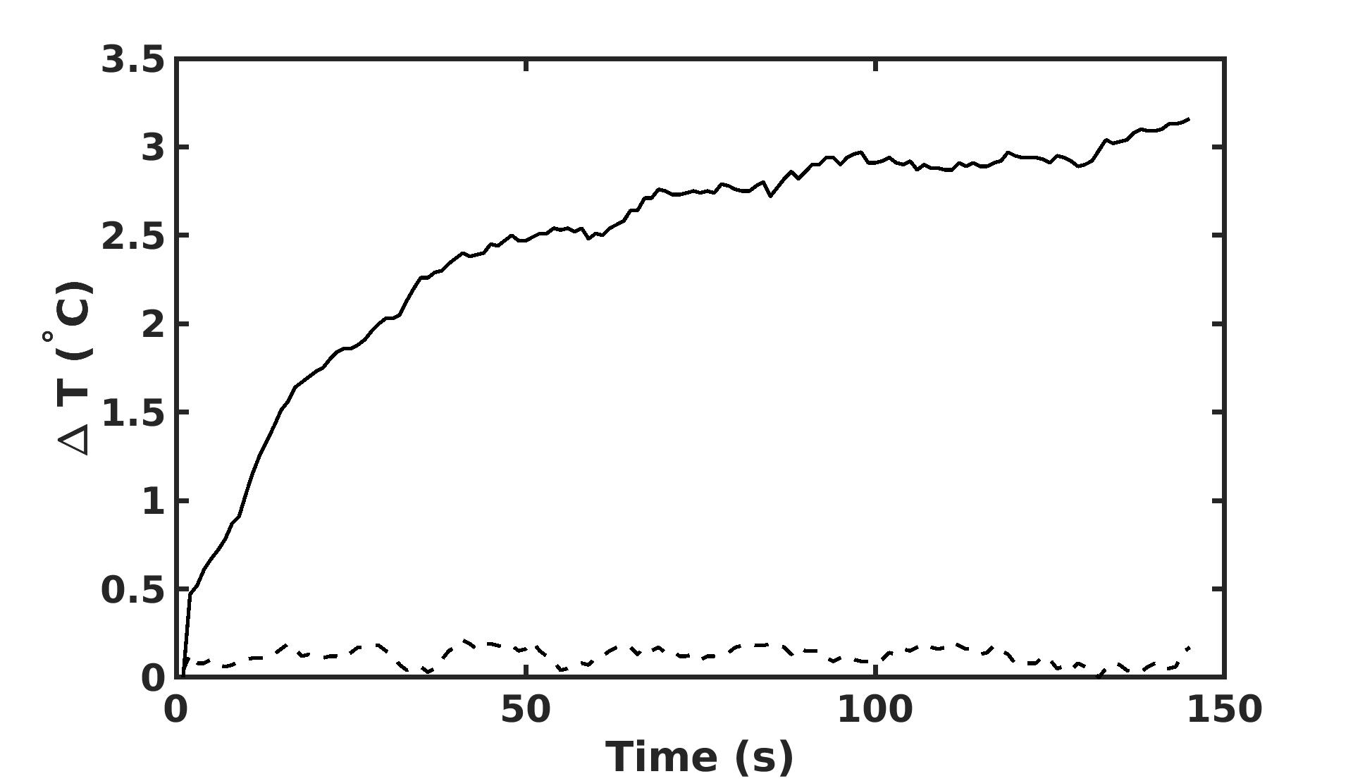
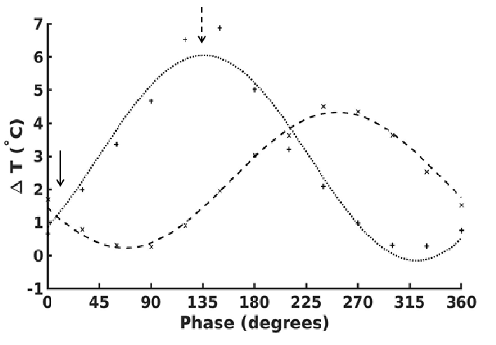
In Figure 1, we show the temperature as a function of time across the full duration of the TSE. A negligible temperature rise was measured in one wire but unacceptable temperature rise ($$$ > 2°$$$) 18 was observed in the other. This demonstrates that a safe operating point for one electrode is not necessarily safe for multiple electrodes.Figure 2 shows the maximum temperature as a function of relative phase. The maximum temperature in each electrode follows the cosine relation predicted by equation (3). A minimum temperature rise can be achieved by appropriate manipulation of the relative phase (arrow, figure 2).
Conclusion
We have generalized the formalism of Eryaman et al. 3,4,7 to include any number of transmitters and implanted electrodes and tested the formalism on a clinically relevant configuration of two transmitters and two electrodes. As the formalism is analytic, it may provide helpful constraints for finding safe operating points in general, allowing patients to benefit from the higher signal-to-noise ratio at higher field strengths.Acknowledgements
We acknowledge support from the Imaging Institute of the Cleveland Clinic and from Siemens Healthineers.References
1. Alexandre Boutet, Clement T. Chow, Keshav Narang, et al. Improving Safety of MRI in Patients with Deep Brain Stimulation Devices Radiology 2020 296:2, 250-262
2. Brown, R. W., Cheng, Y.-C. N., Haacke, E. M., Thompson, M. R., & Venkatesan, R. (Eds.). (2014). Magnetic Resonance Imaging. John Wiley & Sons Ltd. https://doi.org/10.1002/9781118633953
3. Eryaman, Y., Kobayashi, N., Moen, S., et al. A simple geometric analysis method for measuring and mitigating RF induced currents on Deep Brain Stimulation leads by multichannel transmission/reception. NeuroImage, 2019, 184, 658–668. https://doi.org/10.1016/j.neuroimage.2018.09.072
4. Alireza Sadeghi-Tarakameh, Lance DelaBarre, Nur Izzati Huda Zulkarnain et al., Implant-Friendly Excitation Strategies for Imaging DBS Electrodes at 7T, Proceedings of the 30th Annual Meeting of ISMRM, Abstract 414, 2021
5. Eryaman, Y., Guerin, B., Akgun, C. et al. (2015), Parallel transmit pulse design for patients with deep brain stimulation implants. Magn. Reson. Med., 73: 1896-1903. https://doi.org/10.1002/mrm.25324
6. Eryaman, Y., Akin, B. and Atalar, E. (2011), Reduction of implant RF heating through modification of transmit coil electric field. Magn. Reson. Med., 65: 1305-1313. https://doi.org/10.1002/mrm.22724
7. Alireza Sadeghi-Tarakameh , Lance DelaBarre , Nur Izzati Huda Zulkarnain et al., Implant-Friendly MRI of Bilateral DBS Electrodes at 7 T, UHF ISMRM Workshop, Lisbon, Portugal, 2022, Abstract #62.
8. Krack, P., Volkmann, J., Tinkhauser, G. and Deuschl, G. (2019), Deep Brain Stimulation in Movement Disorders: From Experimental Surgery to Evidence-Based Therapy. Mov Disord, 34: 1795-1810. https://doi.org/10.1002/mds.27860
9. Alexandre Boutet, Clement T. Chow, Keshav Narang, et al. Improving Safety of MRI in Patients with Deep Brain Stimulation Devices Radiology 2020 296:2, 250-262
10. Baker KB, Tkach JA, Nyenhuis JA, et al. Evaluation of specific absorption rate as a dosimeter of MRI-related implant heating. J Magn Reson Imaging 2004;20(2):315–320.
11. Baker KB, Tkach JA, Phillips MD, Rezai AR. Variability in RF-induced heating of a deep brain stimulation implant across MR systems. J Magn Reson Imaging 2006;24(6):1236–1242.
12. Finelli DA, Rezai AR, Ruggieri PM, et al. MR imaging-related heating of deep brain stimulation electrodes: in vitro study. AJNR Am J Neuroradiol. 2002 Nov-Dec;23(10):1795-802. PMID: 12427641; PMCID: PMC8185821.
13. Destruel, A, Fuentes, M, Weber, E, et al. A numerical and experimental study of RF shimming in the presence of hip prostheses using adaptive SAR at 3 T. Magn Reson Med. 2019; 81: 3826– 3839. https://doi.org/10.1002/mrm.27688
14. American Society for Testing and Materials (ASTM) . F2182-11a, Standard Test Method for Measurement of Radio Frequency Induced Heating On or Near Passive Implants During Magnetic Resonance Imaging. West Conshohocken, Pa: ASTM International, 2011.
15. Yeung CJ, Karmarkar P, McVeigh ER. Minimizing RF heating of conducting wires in MRI. Magn Reson Med. 2007;58(5):1028-1034.
16. Bhattacharyya PK, Mullin J, Lee BS, Gonzalez-Martinez JA, Jones SE. Safety of externally stimulated intracranial electrodes during functional MRI at 1.5T. Magn Reson Imaging. 2017 May;38:182-188. doi: 10.1016/j.mri.2017.01.012. Epub 2017 Jan 16. PMID: 28104438.
17. MATLAB. 9.9.0.1467703 (R2020b). The MathWorks, 2020
18. Bhusal, B., Stockmann, J., Guerin, B. et al. (2021). Safety and image quality at 7T MRI for deep brain stimulation systems: Ex vivo study with lead-only and full-systems. In H. Celik (Ed.), PLOS ONE (Vol. 16, Issue 9, p. e0257077). Public Library of Science (PLoS). https://doi.org/10.1371/journal.pone.0257077
Figures