2695
An open-source, low-cost 8-channel transmit/receive 3T head coil for pTx developments, MR safety testing and standardization1Physikalisch-Technische Bundesanstalt (PTB), Berlin and Braunschweig, Germany, 2Aarhus University, Center of Functionally Integrative Neuroscience (CFIN), Department of Clinical Medicine, Faculty of Health, Aarhus, Denmark, 3Medical Physics in Radiology, German Cancer Research Center (DKFZ), Heidelberg, Germany, 4University of Minnesota, Center for Magnetic Resonance Research, Minneapolis, MN, United States
Synopsis
Keywords: RF Arrays & Systems, New Devices
This work investigates an open-source, low-cost 8-channel transmit/receive head coil to enable rapid and reproducible pTx development, safety assessment and evaluation at 3T. FDTD simulations were validated with phantom measurements on a 3T with an external pTx system. Relative and absolute 2D/3D B1+-maps were acquired to compute the CP+ mode, and two RF shims were tailored to enforce B1+ efficiency and homogeneity. The open-access design files could serve as a basis for new RF coil designs or pTx projects without needing high expertise in RF coil development or as a cost-effective alternative for multi-centre studies.
Introduction
MRI is driven to increased magnetic fields for higher signal-, contrast-to-noise ratio and spectral resolution. Parallel transmission (pTx) is beneficial to improve flip angle (FA) homogeneity, reduce local and global SAR, or enable mitigation of RF-induced implant heating.1,2 However, researchers typically need access to a 7T system with a commercial pTx system for pTx method developments and/or safety studies. Since not every research group has access to a 7T, more and more home-built (broadband) pTx electronics have been developed in the community that can be hooked to a single-channel scanner. Unfortunately, most commercially available pTx RF coils mainly target 7T systems and are high-cost, closed-source, and inflexible due to a fixed or complex coil design that is difficult to replicate without high expertise in RF-coil development. Moreover, a cost-effective and easy-to-build pTx RF coil solution has the potential to become the new standard for multi-centre or comparative studies because it is much cheaper to build a second coil than to order a commercial one or send a coil back and forth. Here we research and build our own 8-channel TX/RX head coil (<5000€) for 3T applications and make all design files publicly available to enable researchers to replicate the pTx coil quickly. Experimentally acquired 2D/3D relative/absolute B1+-maps and GRE data with tailored RF shims validate the electromagnetic field simulations and B1+-predictions.Methods
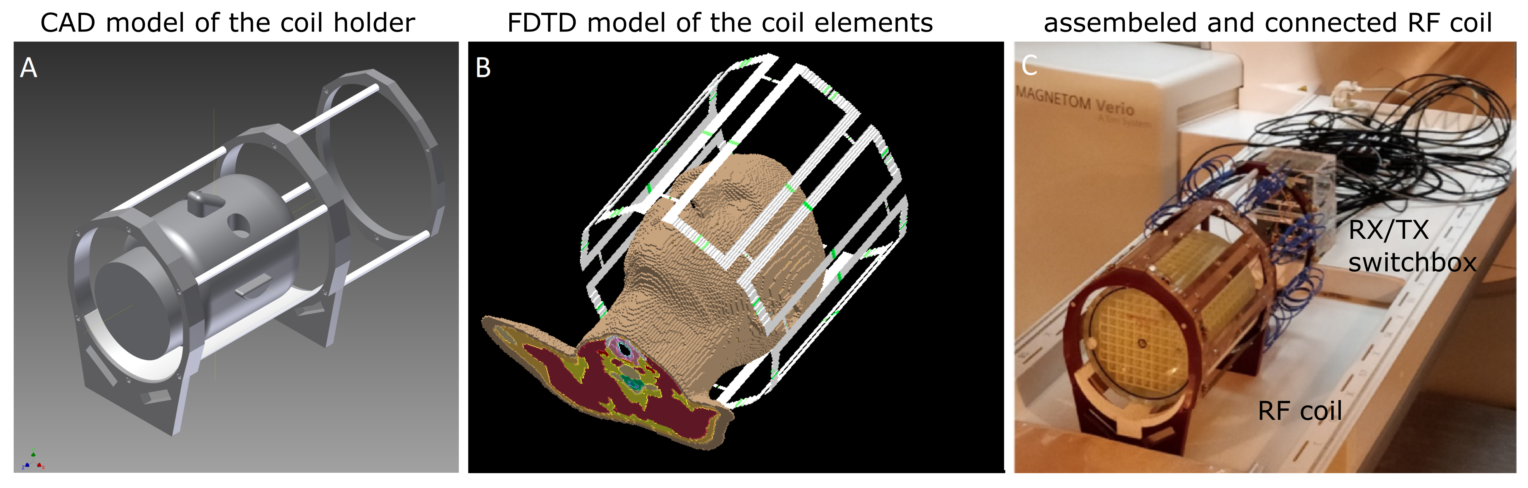
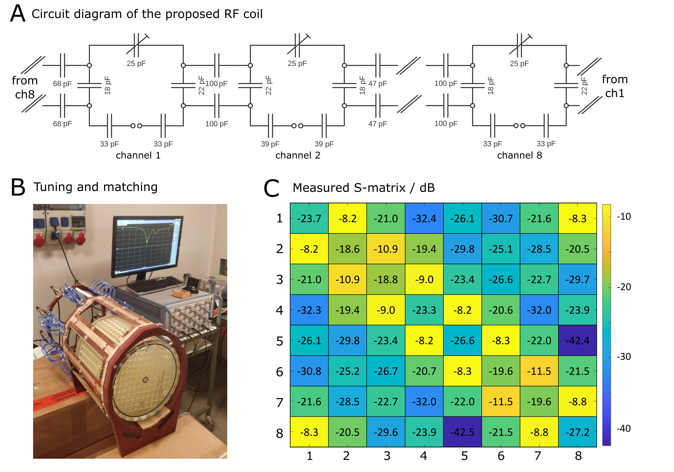
The proposed 3T pTx RF coil design is based on an existing 7T pTx loop RF coil.3 The design translation, 7T→3T, resulted in two significant modifications of eased manufacturing complexity. First, the RF shield could be omitted due to much lower radiation losses at 3T and, secondly, loop element lengths were increased from 160mm to 250mm to enable whole brain imaging and match the lower Larmor frequency. The in-house manufactured loop elements were mounted on a non-conductive frame in an elliptical fashion (7T loop element angles preserved), and plastic rods and a 3D-printed phantom holder for a cylindrical grid phantom4 were added to improve the mechanical stability of the coil. Each loop element carries five capacitors, one trimmable for fine-tuning, optimized through simulations.5 To maintain symmetry, the capacitance at the loop's feeding port was split in half by two equal capacitors. For typical loading conditions, the impedance at the feeding ports is between 10Ω-15Ω. Thus, we realized an impedance matching via a 1:4 transformation in the balun, which was needed because of the required symmetrical drive of the coil element. The balun consists of a half-wave line and two quarter-wave lines. The latter was realized by two 50Ω coaxial cables connected in parallel to achieve the 1:4 transformation. The use of high voltage-resistant components (>1kV) allows for at least 1kW of RF power per channel. MRI was performed on a pTx capable 3T scanner (Siemens Verio, Germany) using an external 8x8kW amplifier (Analogic AN8135S8) and a home-built TX/RX switch box.3 Absolute 2D and 3D B1+-maps were acquired and reconstructed with a magnitude-based preparation pulse method6 and the AFI approach7, respectively. Relative 2D/3D B1+-maps were also obtained.8 Phase-only RF shimming was performed for a region of interest.9 2D/3D GRE scans with parameters fitting to the B1+-scans were acquired to validate the pTx approaches. The RF coil design files are available at https://gitlab1.ptb.de/mri-lab/8ch-ptx-headcoil-3t.Results and Discussion
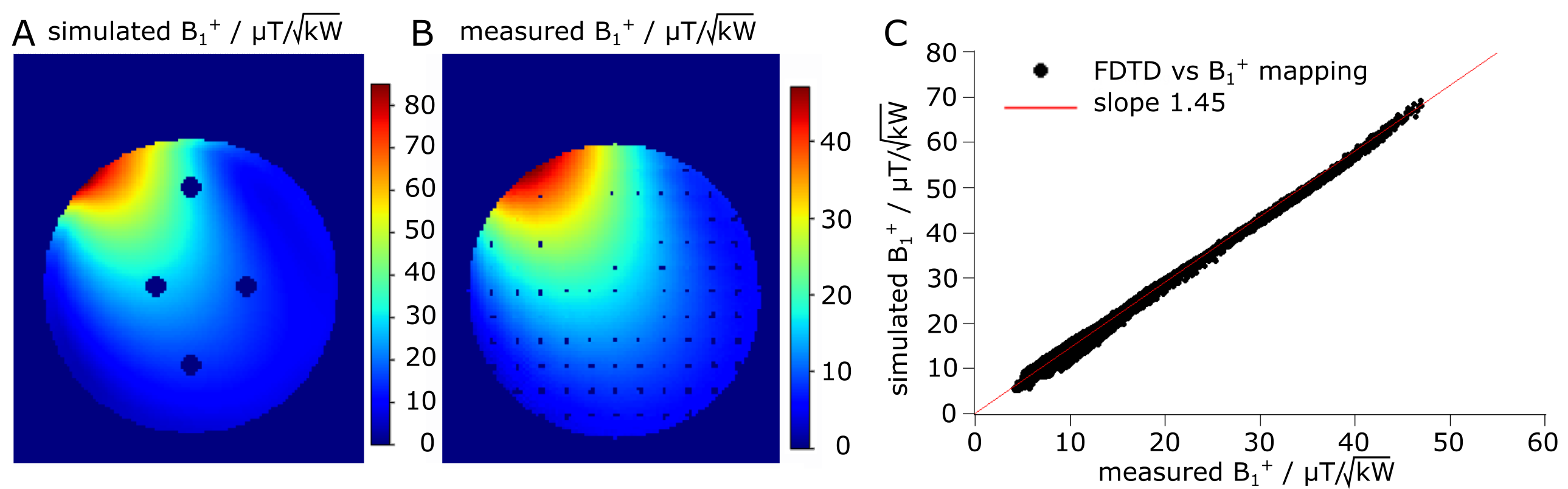
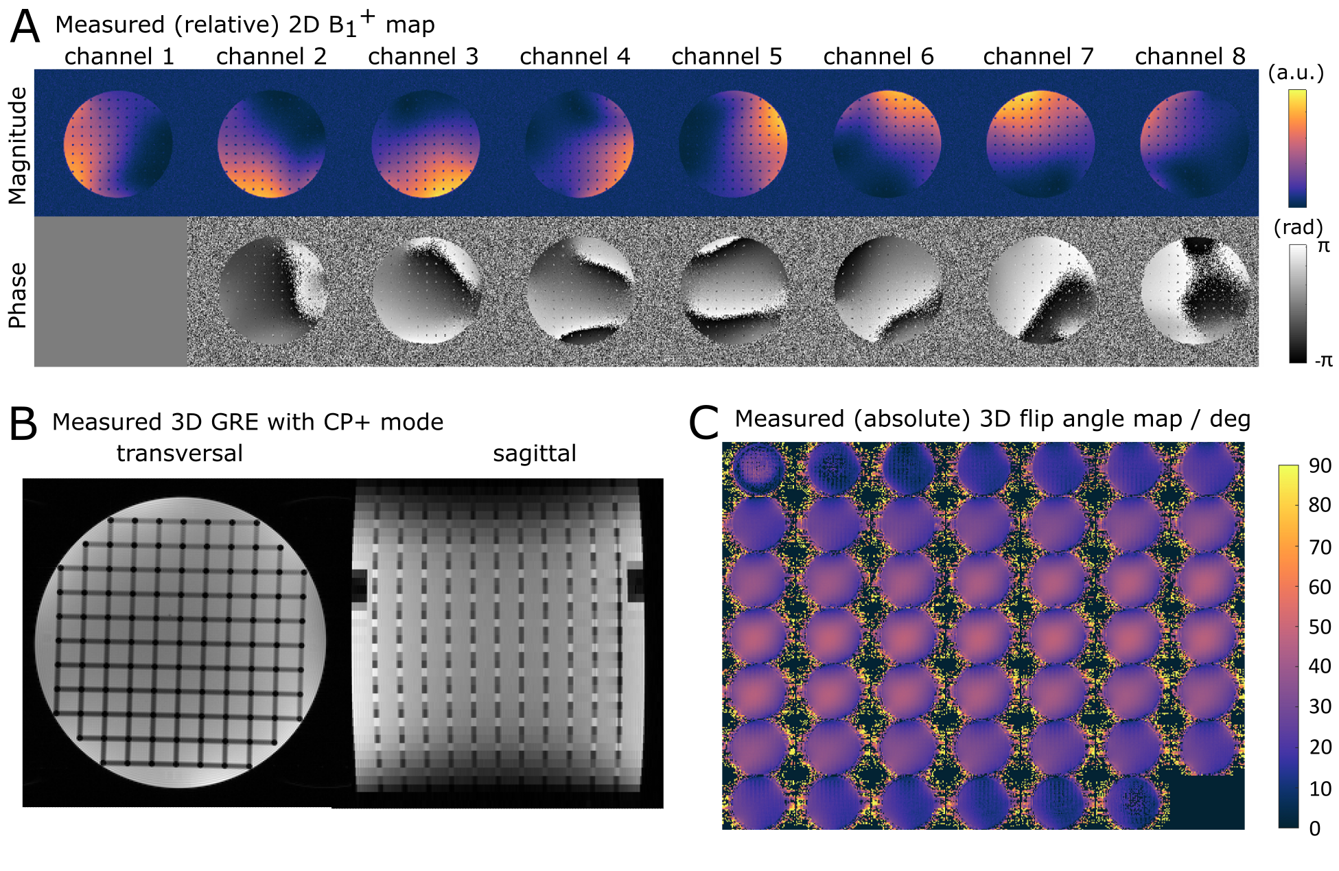
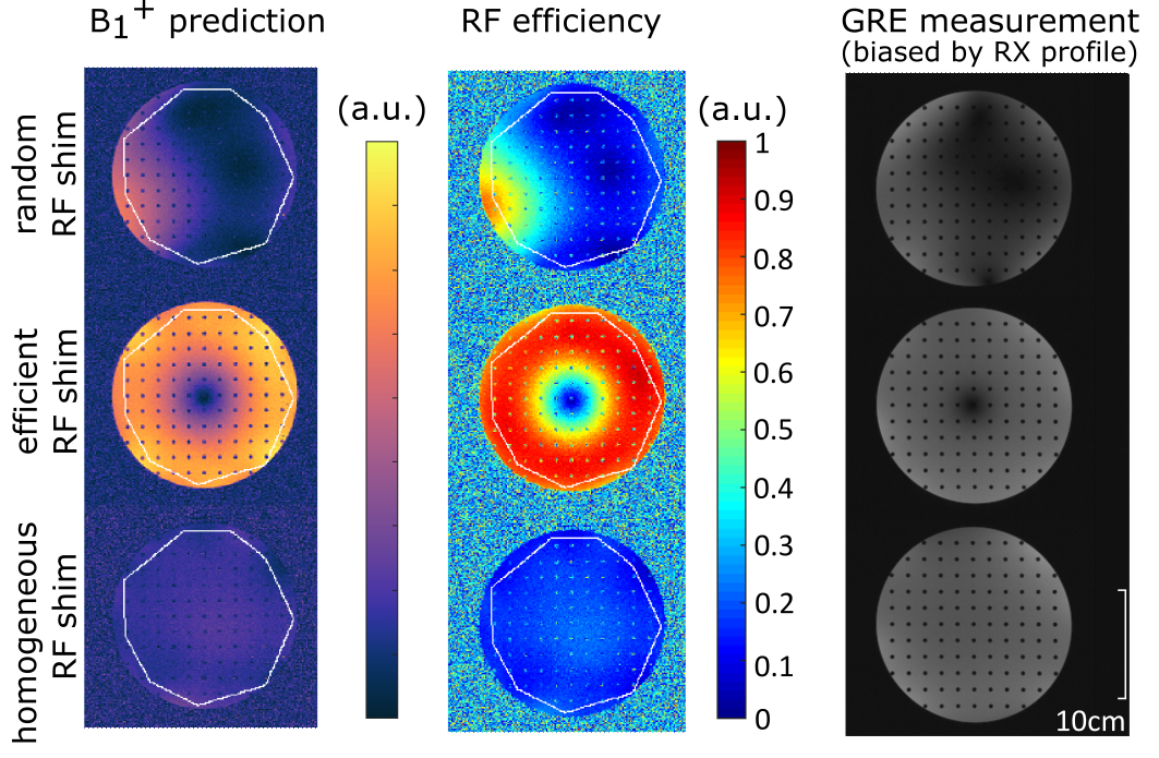
Fig.1 shows the schematic of the proposed coil scaffold, its FDTD voxel grid, and the assembled 8-channel TX/RX RF coil. Fig.2A shows the circuit schematics and the optimized capacitor values to tune and decouple the loops using the variable capacitors (Fig.2B). The measured S matrix (Fig.2C) reflects the simulated parameters and results in a coil coupling of nearest neighbor elements of approximately 8 dB with much less coupling to the other elements. The power loss due to the couplings is around 30%, excluding internal power losses. Fig.3 shows one representative RF channel's simulated and measured absolute B1+-maps (2D preparation-based method). As expected, there is a good agreement between simulated and measured absolute B1+-maps with a scaling factor of 1.45, consistent with the measured voltage losses due to cable loss and TX/RX switch. A similar trend was observed for all eight RF channels, with an average of $$$7µT/\sqrt{kW}$$$ and a range of $$$4.93µT/\sqrt{kW}$$$ and $$$9.82µT/\sqrt{kW}$$$. The combined B1+-efficiency (CP+ mode; not shown) of the coil in the center is approximately $$$35µT/\sqrt{kW}$$$. Fig.4 shows 2D channel-wise relative B1+-maps together with a 3D GRE scan using the CP+ mode and 3D AFI maps in a phantom. For the CP+ mode, the signal maximum occurs in the phantom's center, but if desired, e.g., for single-voxel spectroscopy, it can be steered to other areas of interest with little loss in intensity by different RF shims. Fig.5 shows the results of three different RF shim settings: (i) random, (ii) effective, and (iii) homogeneous RF shim. Qualitatively, there is a good match between the B1+-prediction, RF efficiency and the acquired 2D GRE scan.Conclusion
This work describes the development of a low-cost, easy-to-build, open-source, 8TX/8RX 3T head coil that allows rapid pTx development, safety assessment and 3T pTx applications. In addition, the open-access design files could serve as a basis for new RF coil design or pTx research without needing high expertise in RF coil development.Acknowledgements
This work has received funding from the German Research Foundation (SCHM 2677/4-1, GRK2260), VILLUM FONDEN and the European Partnership on Metrology, co-financed by the European Union's Horizon Europe Research and Innovation Programme and by the Participating States, under grant number 21NRM05 STASIS.References
[1] Silemek, B, Seifert, F, Petzold, J, et al. Rapid safety assessment and mitigation of radiofrequency induced implant heating using small root mean square sensors and the sensor matrix Qs. Magn Reson Med. 2021; 87: 509– 527. https://doi.org/10.1002/mrm.28968
[2] Padormo, F., Beqiri, A., Hajnal, J. V., and Malik, S. J. Parallel transmission for ultrahigh‐field imaging. NMR Biomed., 2016; 29: 1145– 1161. doi: 10.1002/nbm.3313
[3] Winter, L, Seifert, F, Zilberti, L, Murbach, M and Ittermann, B. MRI-Related Heating of Implants and Devices: A Review. Journal of Magnetic Resonance Imaging 53:1646–1665 doi: 10.1002/jmri.27194.
[4] Brühl, R, Ihlenfeld A, Aydin, S, et al. On the comparability of volumetric brain data in the multicentric IMAGEN study. Proc. 21st Annu. Meet. ISMRM, Salt Lake City, Utah, USA: Abstract 893; 2013.
[5] Seifert, F, Pfeiffer, H, Mekle, R, Waxmann, P and Ittermann, B. 7T 8-channel pTx head coil with high B1+ efficiency optimized for MRS. Proc. 24st Annu. Meet. ISMRM, Singapore, Singapore: Abstract 3545; 2016.
[6] Seifert, F, Wübbeler, G, Junge, S, Ittermann, B and Rinneberg, H. Patient safety concept for multichannel transmit coils. Journal of magnetic resonance imaging : JMRI, 26(5):1315–21, 2007.
[7] Yarnykh, V.L. Actual flip-angle imaging in the pulsed steady state: A method for rapid three-dimensional mapping of the transmitted radiofrequency field. Magn. Reson. Med, 2007; 57: 192-200. 10.1002/mrm.21120
[8] Van de Moortele, P and Ugurbil, K. Very fast multi channel B1 calibration at high field in the small flip angle regime. Proc. 17th Annu. Meet. ISMRM, Honolulu, Hawaii, USA: Abstract 367; 2009.
[9] Aigner, CS, Dietrich, S and Schmitter, S. Three-dimensional static and dynamic parallel transmission of the human heart at 7 T. NMR in Biomedicine. 2021; 34:e4450. 10.1002/nbm.4450
Figures