2690
Relaxing exclusion criteria for human subjects in the UHF cardiac MRI with 8Tx/16Rx cardiac array using the SAR analysis for conductive implants.1Chair of Molecular and Cellular Imaging, Comprehensive Heart Failure Center, University Hospital Würzburg, Wuerzburg, Germany
Synopsis
Keywords: RF Arrays & Systems, Safety
The incomplete consensus regarding SAR safety in ultra-high-field MRI leads to a large variety of exclusion criteria for volunteer cohorts in the different centers, especially regarding the acceptance of conductive implants. Therefore, SAR analysis of new commercial transceiver arrays contributes to supplying local IRBs with information regarding the safety of human subjects. This study aimed to analyze SAR for a prototype of a new 8Tx/16Rx array for 7T cardiac MRI. The main goal was to analyze the array safety for human subjects with a different type of passive implant located outside of the array borders.Introduction
MRI at ultra-high B0 field (UHF) is an emerging technique to improve the signal-to-noise ratio (SNR) compared to clinical MRI scanners (1.5-3T). However, the application of UHF MRI faces B1+ homogeneity problems, especially when applied in the thorax and abdominal body regions. Parallel transmit (pTx) technology has been implemented to overcome this problem. However, pTX RF excitation turns the analysis of the electromagnetic (EM) energy deposition in the body (required for subject safety) into a complex problem. So far, the overall problems concerning SAR safety (including simulations, soft- and hardware control, and efficient procedures of finding the appropriate B1+-shimming) did not allow vendors to approach the FDA/CE for certification of 7T MRI of the thorax, and abdomen, or pelvis using transceiver arrays. All UHF MRI studies with such arrays, in particular for cardiac applications, need to be approved by an institutional review board (IRB). Passive conductive implants are usually listed as exclusion criteria due to the tissue heating following RF-array irradiation, which limits the number of potentially suitable subjects for UHF MRI to those without an implant, which makes difficult studies in large cohorts [1]. The incomplete consensus regarding safety leads to a large variety of exclusion criteria for volunteer cohorts in the different centers, especially regarding the acceptance of conductive implants that are remote from the array of conductors. Additional analysis on each new commercial transceiver array is an important contribution, supplying local IRBs with reliable information to allow for informed decisions regarding the safety of human subjects. Therefore, this study aimed to make a consideration of the SAR safety for a prototype of a new 8Tx/16Rx array for 7T cardiac MRI with elements geometry implemented later in a commercial array[2]. The main goal was to analyze the array safety when used in human subjects with a different type of passive implant located outside of the array borders.Method
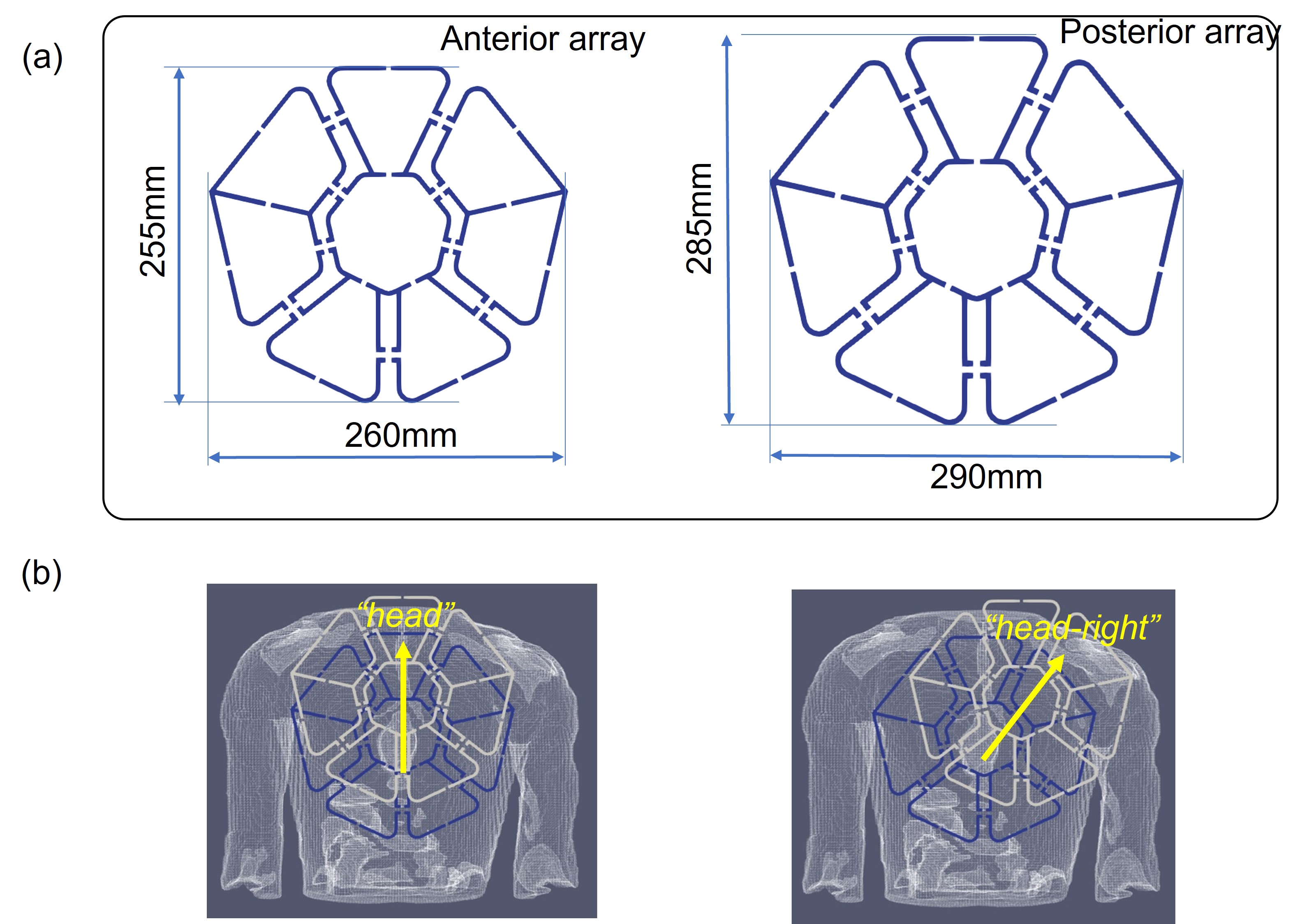
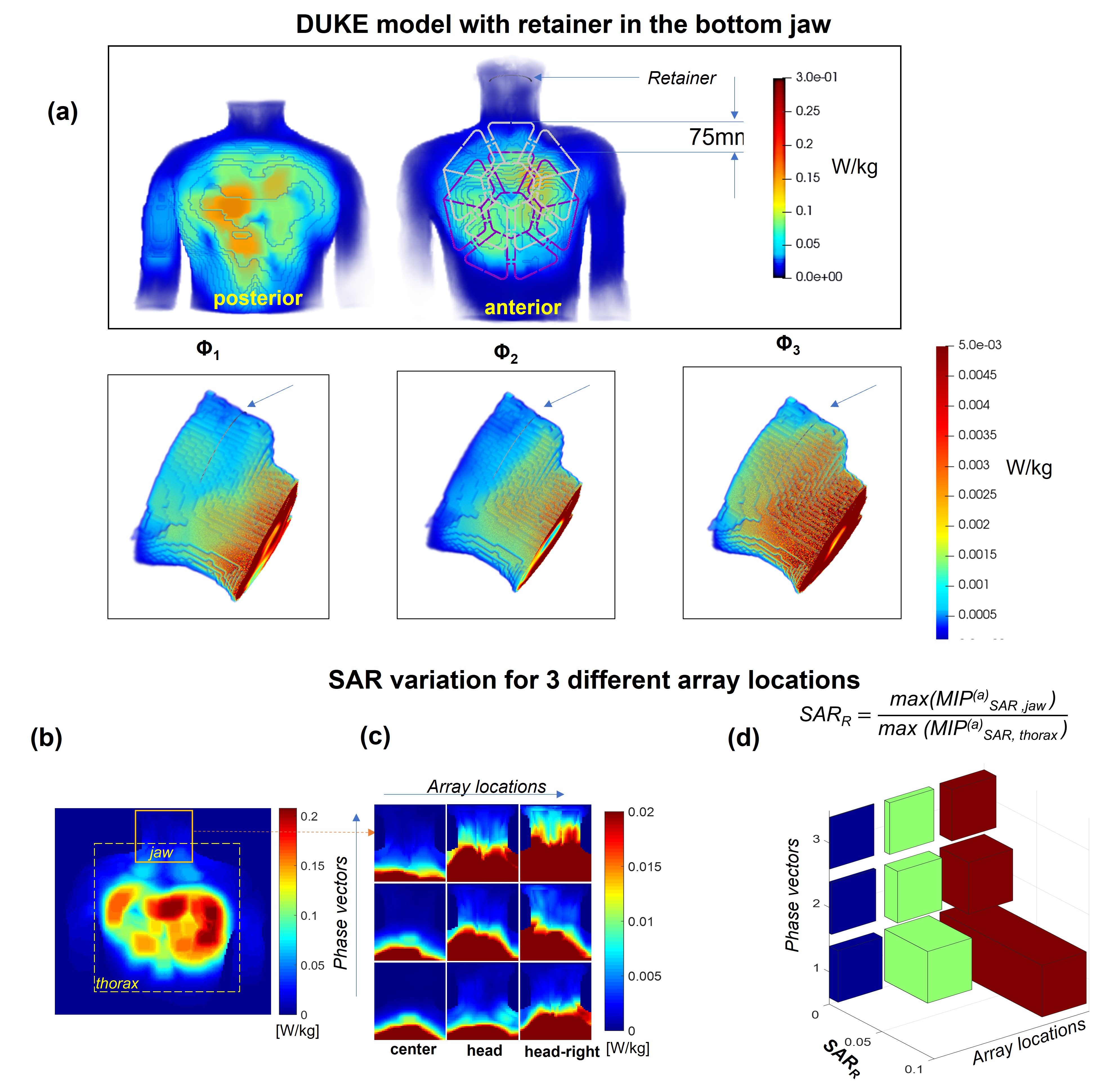
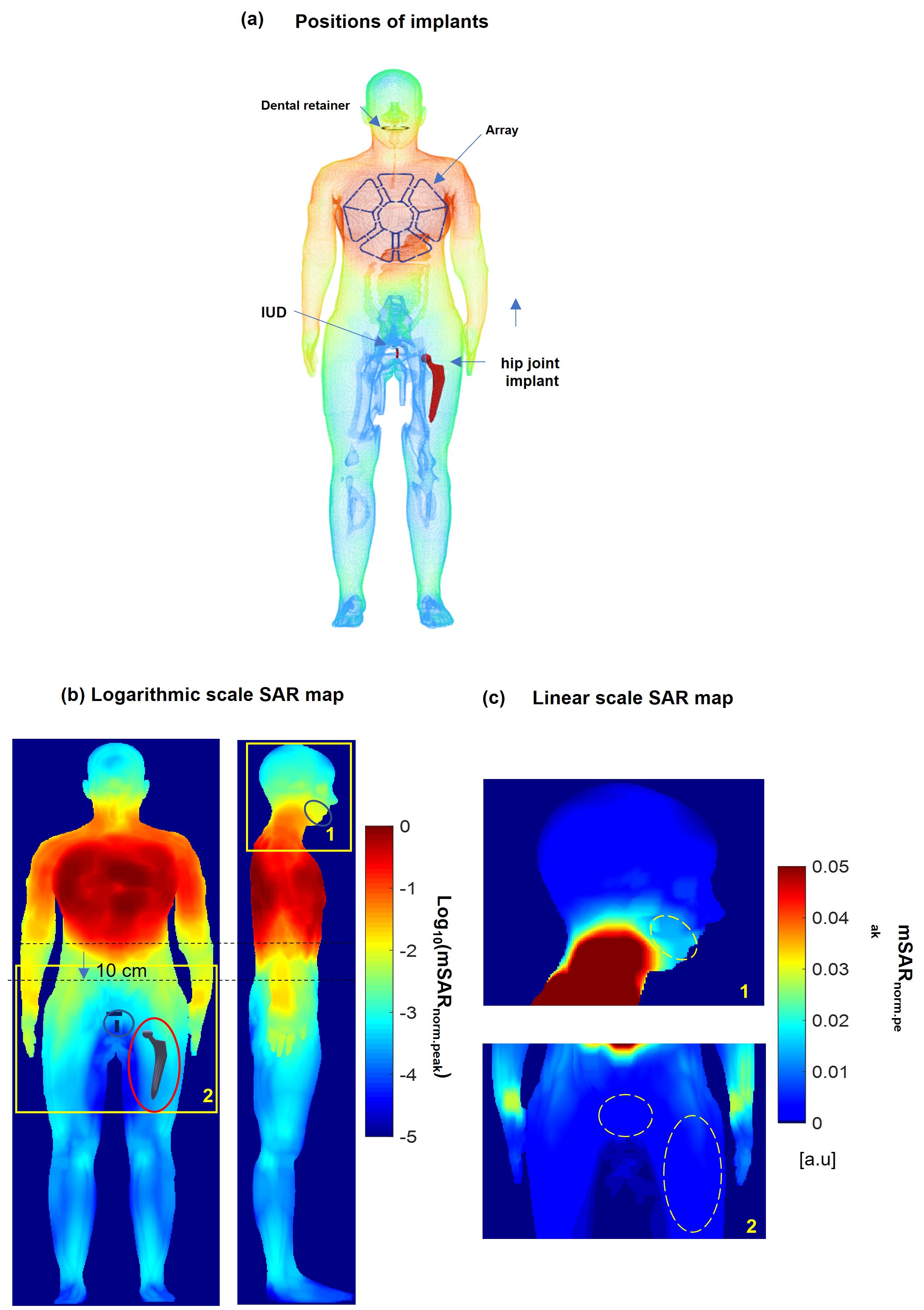
For SAR safety analysis the EM-simulations were performed with CST-Microwave-Studio (CST-MWS, Dassault Systeme) using “Duke” and “Ella” human models (ITI’S Foundation). The local averaged 10g SAR was evaluated using the IEEE/IEC-62704-1. The 16 loop elements of the array were excited with the same normalized input accepted power (Pin =1W) using three optimized static phase-only shim settings computed in the work [[3]]. The simulations of peak SAR were made for (1) a dental retainer (DR) 75mm in length and placed in the lower jaw, (2) a T-shape spiral intra-uterine device (IUD), and (3) a hip joint implant (HJI). The distance from the nearest array edge for the IUD and a hip joint implant is 24 cm and 28 cm respectively. The IUD and HJI were simulated in the “Ella” model and a DR in both models. For all simulations, the array was positioned such that the centers of both anterior and posterior parts (Figure 1a) were located on the body's vertical axes and matched the center of the heart. Additionally, for the Duke model with the allocated DR, the anterior array was simulated shifted to the right-and-head direction (on 50mm), and straight to the head (on 75mm) as shown on Figure 1(b).Results
Figure 2 presents the simulation results for SAR in the presence of a dental retainer in the bottom jaw of the “Duke” model. The peak SAR at 1 W accepted power in the region of the DR does not exceed 0.005 W/kg, whereas as expected the peak SAR under the array is higher by up to two orders of magnitude. The results show that even a 75 mm shift towards the head keeps the SAR in the region of the retainer on average by one order of magnitude lower than the maximal SAR within the array conductor perimeter. Figure 2b with results for diagonal shift confirms this observation. The maximal predicted SAR in the tissue surrounding the retainer does not exceed 10% of the peak value predicted within the array. Figure 3 (a) shows the position of the implants and the results of the SAR simulations in the “Ella” model. The SAR decreases in all the directions in-plane with the array. The peak SAR decreases at least by one order of magnitude within 10 cm from the array perimeter (b,c) Beyond this distance, at 15-20 cm the peak local SAR value is 2..3 orders of magnitude smaller even in the presence of a massive conductive body such as a stainless-steel HJI.Discussion
The simulation results confirm that the local SAR values in all the directions co-planar to the array plane and are negligible compared to the peak values predicted within the array borders. In our opinion, these results can be generalized for considerations regarding SAR safety and massive conductive implants located outside of the array’s perimeter.Conclusion
Based on our results we suggest, for the analyzed array geometry, that the presence of passive electrically conductive implants located beyond 10 cm from the conductor perimeter of the array should not lead to detectable RF-induced tissue heating around the implants if their size and geometry are similar to an IUD or a dental implant. The subjects with such implants may be included in 7T cardiac MRI studies using the considered array type.Acknowledgements
Part of the study obtained financial support from the German Ministry of Education and Research (BMBF) under grants # 01EO1004 & 01EO1504. L.M. Schreiber receives research support from Siemens Healthineers. The position of D. Lohr is partially paid for that research support. We thank Dr. Titus Lanz and Carsten Kögler ( Rapid Biomedical) , Dr. Robin Heidemann and Dr. Adriane Groeger (Siemens Healthineers) for the encouraging and insightful discussions.References
1. Reiter, T., et al., On the way to routine cardiac MRI at 7 Tesla - a pilot study on consecutive 84 examinations. PLoS One, 2021. 16(7): p. e0252797.
2. Terekhov, M.L., D. Reiter, T, Elabyad, I.A., Hock, M., Schreiber, L.M. New commercial 8Tx/16RX array for Clinical Application in 7T Cardiac MRI: initial experience in Healthy Volunteers. in ISMRM Annual Meeting. 2021. Virtual Meeting.
3. Terekhov, M., Elabyad, IA, Resmer, F., Lanz, T., Reiter, T., Lohr, D., Schlöttelburg, W., Schreiber, L.M. Customized B1+-Shaping using Multi-Channel Transceiver Array Prototype for 7T Cardiac MRI with Central Elements Symmetry. in International Society for Magnetic Resonance in Medicine Annual Meeting. 2020. Virtual Meeting.
Figures