2687
Rapid transfer function-based transmission field shimming for safe and B1+ artefact free MRI of implantation sites
Mostafa Berangi1,2,3, Helmar Waiczies2, and Thoralf Niendorf1,2,3
1Berlin Ultrahigh Field Facility (B.U.F.F.), Berlin, Germany, 2MRI.TOOLS GmbH, Berlin, Germany, 3Charité – Universitätsmedizin Berlin, Berlin, Germany
1Berlin Ultrahigh Field Facility (B.U.F.F.), Berlin, Germany, 2MRI.TOOLS GmbH, Berlin, Germany, 3Charité – Universitätsmedizin Berlin, Berlin, Germany
Synopsis
Keywords: Safety, Parallel Transmit & Multiband
Fixation of bone fractures with screws is common clinical practical including follow-up monitoring of the implantation site and of the healing process. MRI-based monitoring can be compromised by tissue heating and transmission field distortion. To overcome this challenge, this work uses parallel transmission using an optimal transmission vector. The proposed approach leverages a single EMF simulation without the implant, while the effect of implant electromagnetic scattered fields are estimated using a transfer matrix. Optimal shim vectors are computed by an optimization process using a multilevel genetic algorithm. Our findings demonstrate the feasibility and performance of the transfer function driven approach.Introduction
Bone fracture fixation using screws is common clinical practice.1 Biodegradable screws2 are currently clinically available, and they substantially improve patient comfort by eliminating the need for implant removal surgery. After implantation, the healing process at the implant site, and the corrosion status of the biodegradable implants are closely monitored3. MRI can be used to study the implant-tissue interface and the degradation status of biodegradable implants4. However, the electrically conductive nature of implants presents challenges for MRI, including: 1) MR safety risks due to concentrated energy deposition in tissue adjacent to the implant 5; 2) B1+ field distortions resulting from the implant-induced scattered radiofrequency (RF) field. These constraints can be greatly reduced or eliminated by parallel transmission of multichannel RF coil arrays. Recognizing this opportunity, recent reports have demonstrated the feasibility of safe MRI of small implants at 7.0 T.6,7 We propose a generalized approach, to translate these findings to any patient, with arbitrary implant geometry, location and positioning, and to any RF coil configuration. This approach leverages a single EMF simulation without the implant, estimating the implant electromagnetic scattered fields using an implant-specific transfer matrix.Material and method
EMF distribution of an 8-channel modular loop-dipole RF transceiver8 placed around a cylindrical phantom (r=85mm; L=300mm) mimicking the electrical properties of muscle tissues was simulated at 297.2 MHz (Fig.1) (CST Studio Suite 2022, CST MWS). Next, the transfer matrix9 of a metallic rod (r=2mm, L=70mm) mimicking an implant was calculated. The transfer matrix defines the current distribution along the implant resulting from incidence of a localized and purely tangential electric field along a certain spatial length on the implant. This localized excitation was simulated in CST by importing the EMFs from two counter-propagating plane wave in a 100×100×5mm3 domain as source fields into another simulation with the implant. The current distribution along the implant in a scenario where the implant is placed at any arbitrary location and orientation inside the phantom can be estimated in the first step using the transfer matrix and incident tangential electric field of the RF transceiver. The B1+, tangential E-field and specific absorption rate (SAR) derived from the first step, along with the transfer matrix deduced from the second step were incorporated into an optimization step using a multi-objective genetic algorithm (GA) that aims to maximize a uniform B1+ in a cylindrical (r=20mm; L=110mm) region of interest (ROI), while minimizing SAR and implant-induced current throughout the simulation domain. The result of the optimization is a (GA-driven) excitation vector that provides a strong and uniform B1+ in the ROI, while avoiding SAR increase at the implantation site, and minimizing SAR throughout the phantom. The performance of this optimized excitation vector was evaluated in another simulation in which an implant was inserted into the phantom at the exact location for which the optimization was performed. For benchmarking this excitation vector was compared to the CP mode.Result
An example current distribution along the implant is shown in Figure2 together with the corresponding transfer function. B1+ and point SAR maps obtained for GA-driven and CP excitations derived from the simulations w/wo the implant are shown in Figure 3. For transmission field shimming using the CP algorithm, a strong bow-shaped B1+ void was formed close to the implant. GA transmission field shimming eliminated B1+ artefacts, and hence facilitated the acquisition of uniform images close to the implant. The SAR reduction of the GA approach over the CP approach is highlighted in Figure4. Notwithstanding the strong and uniform B1+ field in the implant region, the GA-driven excitation vector derived from the simulations w/wo the implant in conjunction with the transfer function successfully eliminated implant SAR. For comparison, CP-based excitation showed substantial SAR hot spots at the tips of the implant. The performance gain of the transfer function-based GA approach benefits MRI of the implant site.Discussion
CP excitation induces B1 artifacts near the implant and excessive local RF power deposition. These constraints are detrimental, or even prohibitive for MRI of implant sites. This work demonstrates that pTX, in conjunction with transfer function-driven genetic algorithms for transmission field shaping, ensures MR safety and transmission field uniformity suitable for MRI-aided monitoring of tissue healing of implantation sites, including MRI characterization of the degradation state of biodegradable orthopedic implants. While the impact of the RF transmit array on the efficiency of GA-based excitation vector optimization is acknowledged, it stands to reason that the approach proposed and evaluated here is compatible with any RF array with an arbitrary number of transmit channels to facilitate safe and B1+ distortion-free MRI of implants. The proposed transfer function-driven approach is not limited to scenarios where there is only one implant in the simulation domain, but supports more than one implant, if coupling between implants is negligible.Conclusion
Our findings help to meet MR safety and transmission field uniformity requirements of MRI-guided implant site monitoring. Notwithstanding that this proof-of-principle study was demonstrated at 7.0 T, the proposed approach provides a technological basis for MRI of orthopedic and other conducting implants at clinical field strengths.Acknowledgements
This project is supported by the H. 2020 European Training Network of the European Union (MgSafe, grant agr. No. 811226)References
1. Slone, R. M., Heare, M. M., vander Griend, R. A. & Montgomery, W. J. Orthopedic fixation devices. https://doi.org/10.1148/radiographics.11.5.1947319 11, 823–847 (1991). 2. Luthringer, B. J. C., Feyerabend, F. & Römer, R. W. Magnesium-Based Implants: A Mini-Review. Magnesium Research Preprint at https://doi.org/10.1684/mrh.2015.0375 (2014). 3. Myrissa, A. et al. In vitro and in vivo comparison of binary Mg alloys and pure Mg. Materials Science and Engineering C (2016) doi:10.1016/j.msec.2015.12.064. 4. Paramitha, D. et al. Monitoring degradation products and metal ions in vivo. Monitoring and Evaluation of Biomaterials and their Performance In Vivo 19–44 (2017) doi:10.1016/B978-0-08-100603-0.00002-X. 5. Winter, L., Seifert, F., Zilberti, L. & Murbach, M. MRI-Related Heating of Implants and Devices : A Review Physics of Implant Heating. 1–20 (2020) doi:10.1002/jmri.27194. 6. Mostafa Berangi, Andre Kuehne, Helmar Waiczies & and Thoralf Niendorf. Excitation vector optimization for safe parallel transmission MRI of passively conducting implants in the presence of motion. in (2022). 7. Mostafa Berangi, Andre Kuehne & Thoralf Niendorf. Safe 7T MRI of tissues neighboring Mg-based biodegradable implants using parallel transmission. in (2021). 8. Ertürk, M. A., Raaijmakers, A. J. E., Adriany, G., Uğurbil, K. & Metzger, G. J. A 16-channel combined loop-dipole transceiver array for 7 Tesla body MRI. Magn Reson Med (2017) doi:10.1002/mrm.26153. 9. Tokaya, J. P., Raaijmakers, A. J. E., Luijten, P. R., Sbrizzi, A. & van den Berg, C. A. T. MRI-based transfer function determination through the transfer matrix by jointly fitting the incident and scattered field. Magn Reson Med 83, 1081–1095 (2020).Figures
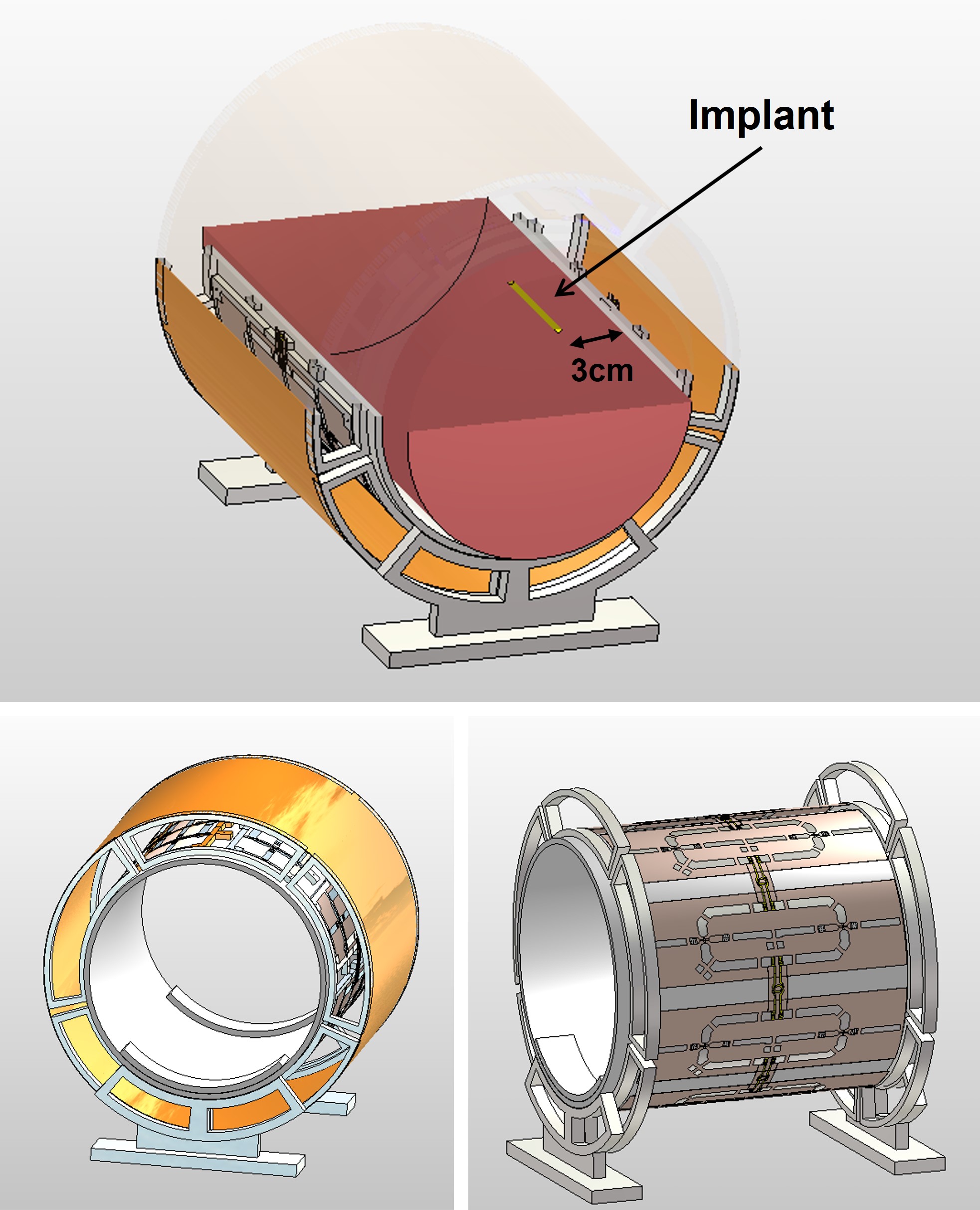
Figure 1:
RF transceiver representing different sections of the RF array with the
position of the phantom and implant inside the phantom.
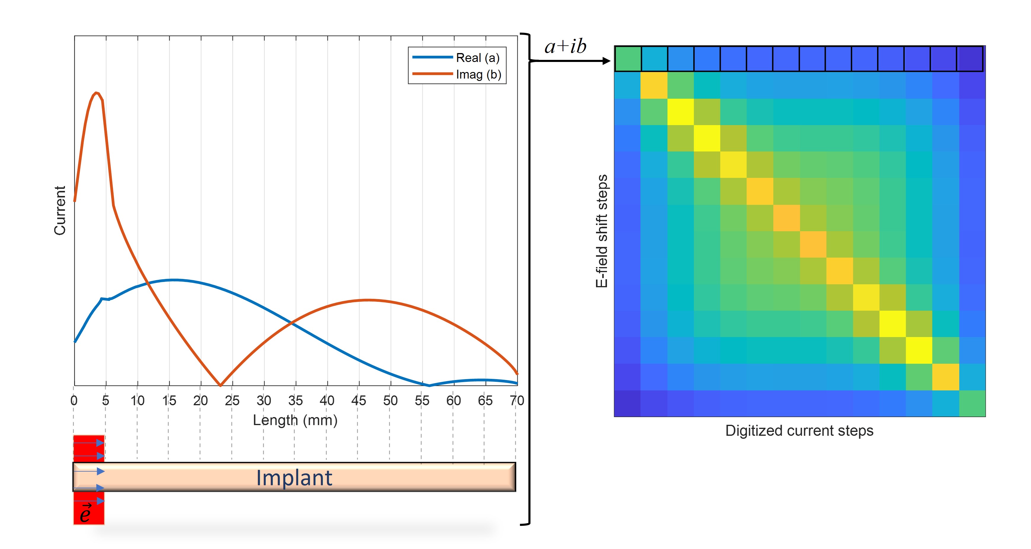
Figure 2:
Transfer function: Implant excited with a localized e-field, and corresponding induced
current is plotted. This current was then digitized and forms the transfer
function.
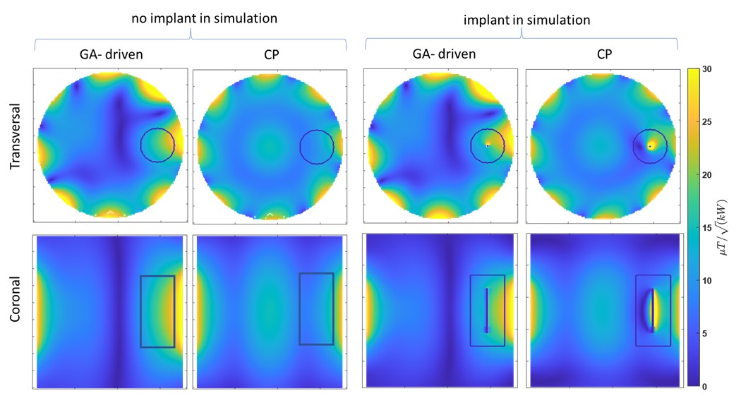
Figure 3;
left two -columns) Simulation results of transversal (top row) and coronal (bottom
row) B1+ maps at the center of the implant corresponding
to GA-driven and CP excitation without implant. The ROI is shown as a black
contour. Right two columns) B1+ maps of the same
simulation setup but with the implant placed inside the phantom.
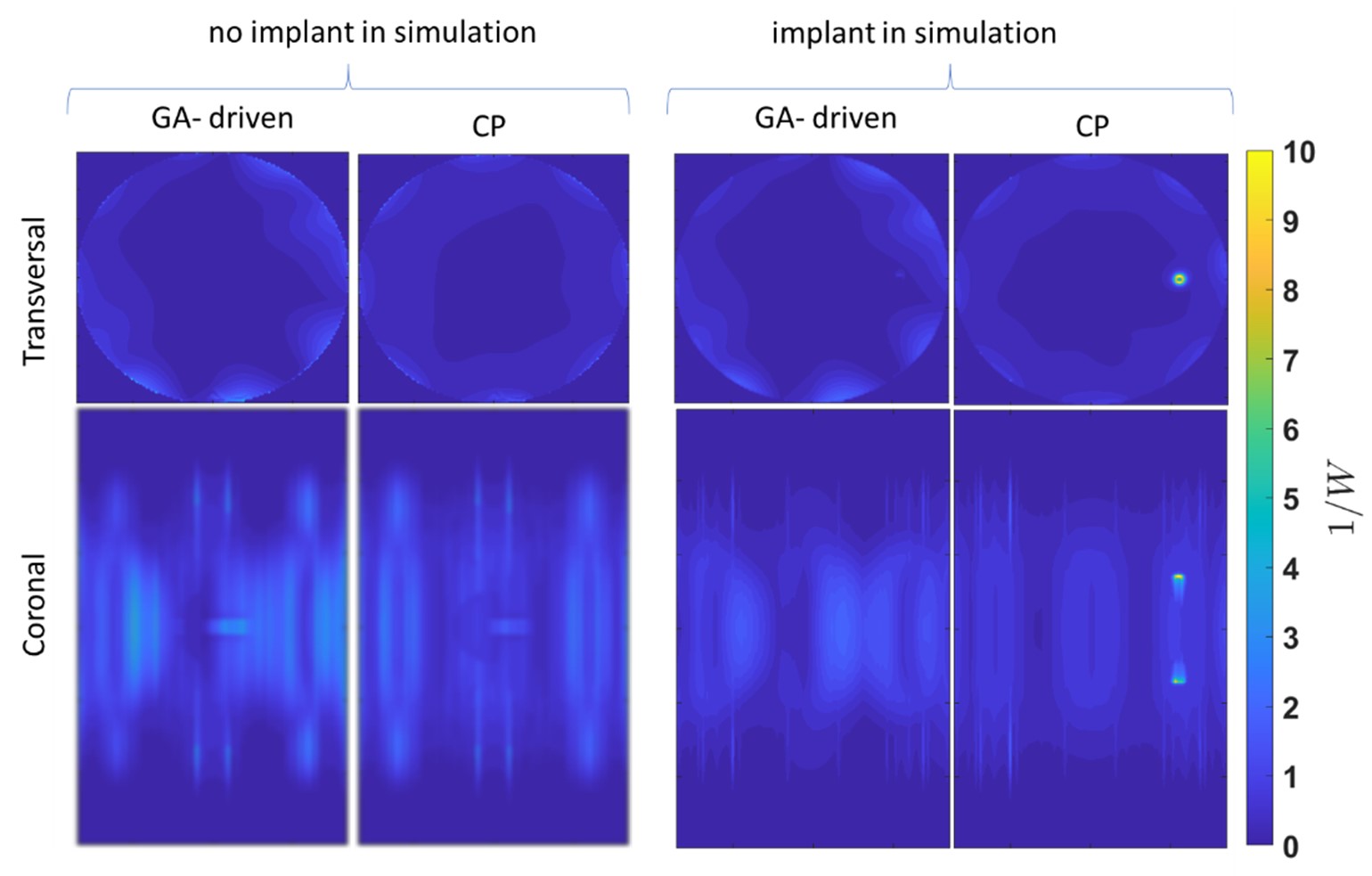
Figure 4:
Transversal and coronal SAR maps obtained for GA-driven and CP transmission in
un-averaged with and without the implant. The maps are projection of maximum SAR
though all available slices.
DOI: https://doi.org/10.58530/2023/2687