2232
Model-Based Dynamic B0 Compensation of a 0.35T MRI-Linac using Inclinometer Data1Biomedical Engineering, Washington University in Saint Louis, Saint Louis, MO, United States, 2Radiation Oncology, Washington University School of Medicine, Saint Louis, MO, United States, 3Duke University, Durham, NC, United States, 4Radiology, Washington University School of Medicine, Saint Louis, MO, United States
Synopsis
Keywords: Artifacts, MR-Guided Interventions
Balanced steady state free procession (bSSFP) sequences are commonly used for real-time imaging during MRI guided radiotherapy treatments (MR-IGRT). bSSFP sequences offer high temporal resolution and SNR but are sensitive to B0 fluctuations which lead to imaging artifacts during radiotherapy (RT) gantry rotatation.1 Previous work demonstrated that RT gantry rotation induced artifacts could be significantly reduced by compensating for B0 fluctuations using data from a free induction decay (FID) navigator prior to each bSSFP image.2 A model-based approach to B0 compensation using the gantry inclinometer was evaluated to reduce the SNR loss and temporal resolution associated with the navigator approach.Purpose
The ViewRay MRIdian 0.35T MRI-Linac utilizes six ferromagnetic shield buckets spaced 60° to house accelerator components. While stationary, RT gantry angle dependent B0 offsets are relatively small (± 40 Hz). During gantry rotation, the magnetic shields result in large B0 fluctuations (± 400 Hz). These B0 fluctuations result in imaging artifacts (null bands) and isocenter misalignments between the MRI and radiotherapy systems which can affect tumor tracking and treatment accuracy.3 As a result, commercial MR-IGRT systems are limited to step and shoot delivery, meaning that the gantry and multi-leaf collimators (MLCs) are stationary while the radiation beam is on.4–6 While step and shoot delivery avoids the imaging issues associated with gantry rotation, treatment times can be longer and target conformality can be worse than volumetric modulated arc therapy (VMAT).7–10 MRI guided arc therapy will require dynamic B0 compensation to ensure adequate target tracking, image quality, and patient safety.Methods
Center frequency offsets during gantry rotation were acquired at 7.4 frames/s using a FID navigator employing a nonselective RF excitation pulse (flip angle: 35◦, RF duration: 500 μs, acquisition dwell time:8 μs,64 complex data points). The navigator was incorporated into a sagittal 2-D Cartesian bSSFP cine sequence. Measurements were acquired on a 24 cm diameter spherical phantom doped with 5 mM NiSO4 (T1/T2: 330/260 ms) using the system body coil.Gantry angles positions were obtained from the inclinometer on the MRI-Linac via the motion controller. To reduce the noise in the data, the gantry angle data was smoothed by computing the 11-point moving average. To calculate the angular velocity of the RT gantry, a symmetric low-pass differentiator with an 11-point window length was numerically convolved with the inclinometer data. These filters resulted in a 0.125 second delay in the gantry angle data.
To estimate the B0 fluctuations using the inclinometer data, a model was created based on the convolution of a sinusoidal input function (s) and a long time-constant eddy current transfer function (m): $$\Delta f (t) = s(t) \otimes m(t) \\ s(t) = \left(A \cdot \mid \frac{\dot{\theta}(t)}{\omega_{max}}\mid \cdot \sin{\left[6 (\theta (t) + B) \right]} \right)(u \left[t_{start} \right] - u \left[t_{start} - t_{end} \right]) + C\\ m(t) = D\cdot Exp[\frac{-t}{\tau}]\cdot u[t]\\$$
A-D and $$$\tau$$$ are fitting parameters, $$$\omega_{max}$$$ is the maximum angular velocity (0.06 rad/s for the 0.35T MRI-Linac). $$$\theta (t)$$$ is the gantry angle at time $$$t$$$ in radians. $$$\dot{\theta}(t)$$$ is the angular velocity. $$$u$$$ is the Heaviside step function with start and stop times indicated by $$$t_{start}$$$ and $$$t_{end}$$$. The factor of 6 appears in the sine function due to the gantry mounted mu-metal shield buckets spaced every 60°. $$$\frac{\dot{\theta}(t)}{\omega_{max}}$$$ scales the amplitude of the sinusoidal function by the gantry velocity.
The model was fit using MATLAB 2022a for a complete clockwise (33°→180°→360°→30°) and a complete counterclockwise (30°→0°→270°→33°) gantry rotation. By design, the gantry cannot travel to 31° or 32°. The fits were separated into clockwise and counterclockwise rotations due to the observed asymmetry in the central frequency between rotation directions.1 The models were then compared to center frequency offsets from a 30° gantry rotation (cw: 300° → 330°, ccw: 330° → 300°) using the parameter estimates from the full gantry rotations. Root mean square errors (RMSE) between the model estimates and measured B0 fluctuations were calculated.
Results
The model displayed a good fit with both the complete clockwise gantry rotation (RMSE = 23.23 Hz) and the complete counterclockwise gantry rotation (RMSE = 25.74 Hz). Likewise, the model estimation demonstrated good agreement with the 30° gantry rotations (RMSE = 19.58 Hz for 300° to 330° rotation and RMSE = 23.28 Hz for 330° to 300° rotation). Counterclockwise fits are shown for the full gantry rotation (Figure 2) and the 30° counterclockwise gantry rotation (Figure 3). Fits could likely be further improved by replacing the DC offset parameter (C) with a look-up table of static B0 offsets at varying gantry angles.Conclusions
A model-based approach may provide a means of compensating for the large B0 fluctuations that occur during the gantry rotation of an MRI-Linac without incurring the SNR or temporal resolution penalties of a navigator-based approach.Acknowledgements
No acknowledgement found.References
1. Michael Gach, H., Curcuru, A. N., Kim, T. & Yang, D. Technical Note: Effects of rotating gantry on magnetic field and eddy currents in 0.35 T MRI-guided radiotherapy (MR-IGRT) system. Med. Phys. 48, 7228–7235 (2021).
2. Curcuru, A. N., Kim, T., Yang, D., Gach, H. M. & Gach, C. H. M. Real-time B 0 compensation during gantry rotation in a 0.35-T MRI-Linac. (2022) doi:10.1002/mp.15892.
3. Kim, T. et al. Characterizing MR Imaging isocenter variation in MRgRT. Biomed. Phys. Eng. Express 6, (2020).
4. Mutic, S. & Dempsey, J. F. The ViewRay System: Magnetic Resonance-Guided and Controlled Radiotherapy. Semin. Radiat. Oncol. 24, 196–199 (2014).
5. Green, O. L. et al. First clinical implementation of real-time, real anatomy tracking and radiation beam control. Med. Phys. 45, 3728–3740 (2018).
6. Raaymakers, B. W. et al. First patients treated with a 1.5 T MRI-Linac: Clinical proof of concept of a high-precision, high-field MRI guided radiotherapy treatment. Phys. Med. Biol. 62, L41–L50 (2017).
7. Holt, A. et al. Multi-institutional comparison of volumetric modulated arc therapy vs. intensity-modulated radiation therapy for head-and-neck cancer: a planning study. (2013) doi:10.1186/1748-717X-8-26.
8. Xhaferllari, I., El-Sherif, O. & Gaede, S. Comprehensive dosimetric planning comparison for early-stage, non-small cell lung cancer with SABR:fixed-beam IMRT versus VMAT versus TomoTherapy. J. Appl. Clin. Med. Phys. 17, 330 (2016).
9. Cho, I. et al. Dosimetric analysis of stereotactic rotational versus static intensity-modulated radiation therapy for pancreatic cancer. (Cancer Radiother, 2018).
10. Oliver, M., Ansbacher, W. & Beckham, W. A. Comparing planning time, delivery time and plan quality for {IMRT}, {RapidArc} and {Tomotherapy}. (Phys, 2009).
Figures
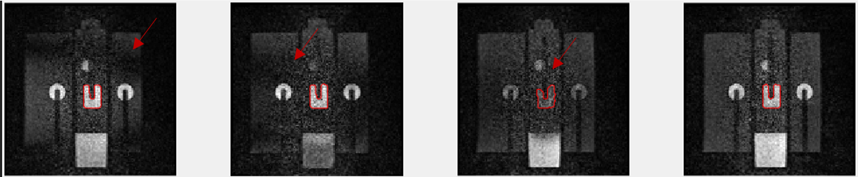
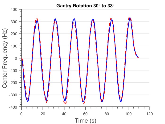
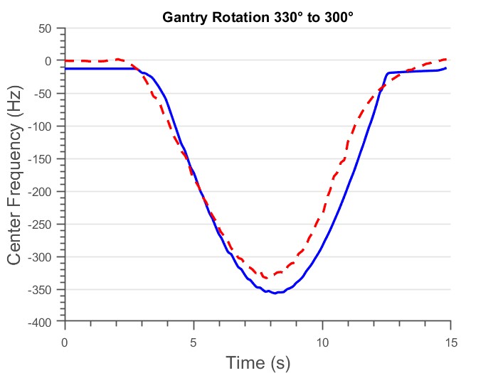
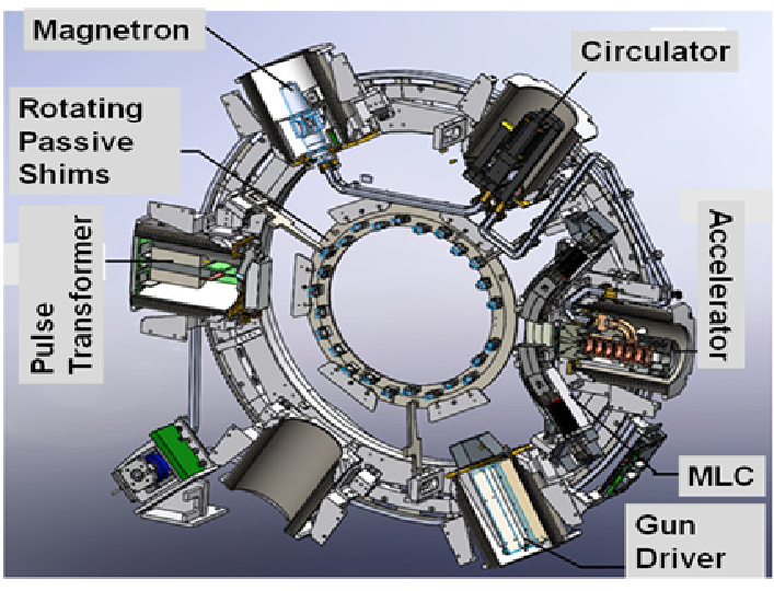
Figure 4: Illustration of the 0.35T MRI-Linac gantry depicting the six mu-metal buckets and rotating passive shim tray. The 60° radial spacing between the shield buckets results in the periodic B0 offsets observed during gantry rotation.