2213
Reproducing the effect of Steady-State stabilization on MR signals and images and its relation to pulse sequences by MRI simulation
Noriyuki Tawara1 and Daiki Tamada2
1Department of Radiological Sciences, Faculty of Health Sciences, Japan Healthcare University, Sapporo, Japan, 2Department of Radiology, Yamanashi University, Yamanashi, Japan
1Department of Radiological Sciences, Faculty of Health Sciences, Japan Healthcare University, Sapporo, Japan, 2Department of Radiology, Yamanashi University, Yamanashi, Japan
Synopsis
Keywords: Visualization, Visualization
The objective of this study was to reproduce the generation process of Steady-State and FLASH Band in MRI phenomena that cannot be reproduced by the actual equipment because of the restrictions imposed by venders, in order to directly confirm their relationship with pulse sequences. MRI simulation can reproduce Bloch equation faithfully, and thus it is possible to reproduce the relation between pulse sequences and the phenomena related to MRI as numerical data.Purpose
Assuming ideal conditions, MR images similar to those of the actual scanners can be reproduced computationally using the Bloch equation1, which is widely a used simulation method. On the other hand, it has been considered difficult to simulate realistic MR images within the practical computational time since solving the equation is computationally expensive. However, recent advancement in computational power enables complicated simulation of MR imaging. MR images using Steady-State can reduce the image scanning time, but the early imaging methods generated the image artifact as FLASH Band2, which had to be controlled. Although a solution for FLASH Band has already been established, it is not possible to reproduce the mechanism in actual equipment due to the limitations of vendors. The purpose of this study was to generate the Steady-State phenomenon (Steady-State) and FLASH Band, which is challenging to reproduce with the actual equipment due to constraints of its system interfaces, using an MRI simulation and to demonstrate the relationship among Steady-State, FLASH Band and the pulse sequence.Methods
Two numerical phantoms with the matriz size of 256×256 were prepared, and a) MR signal and b) MR image data were obtained by MRI simulation. The phantom consists a) of 1-pixel with T1 of 1000 ms and T2 of 100 ms placed at the center. The other phantom has for b) co-axial cylindrical regions with different T1/T2(Figure 1). The proton density (PD) for both phantoms was set at 1000. MRI simulations were implemented by BlochSolver3 (MRIsimulations Inc., Tokyo, Japan), which is the Bloch-Torrey equation-based MRI simulator. Two gradient echo sequences (GrE) a-1) without and a-2) with spoiler gradient were used for the phantom a), as shown in the pulse sequence diagrams in Figure 2. An RF phase increment angle of 117˚4 was used for the RF pulses. All conditions except gradient and increment angle were common and TR=40 ms, TE=6 ms, FA=30, the number of phase-encoding (PE)=256, and slice thickness=5 mm. The number of subvoxels in the x, y, z directions were 32, 1, 1, respectively. Two GRASS sequences with b-1) without and b-2) with PE rewinder, and b-3) spoiled GRASS (SPGR) were used, as shown in the pulse sequence diagrams in Figure 3. All conditions except gradient and RF increment angle were common and TR 25 ms, TE 10 ms, FA 30, and slice thickness 5 mm. The number of subvoxels in the x, y, z directions were 8, 1, 8, respectively. The calculations for MRI simulation were performed on a laptop PC (OS: Windows 10) equipped with GPU (GeForce GTX 1650, 1024 CUDA core, NVIDIA, Santa Clara, CA). Data processing acquired by MRI simulations was performed using Interactive Data Language software (IDL; Harris Geospatial Solutions KK, Boulder, CO, USA).Results and Discussion
Figure 4 shows FID signals (imaginary part) and MR signals with and without the addition of spoiler gradient. Although the signal evolution does not completely reach Steady-State as the number of excitation increases because the spoiler gradient is not used in Figure 4a, FID signal is shown to be stable even when the RF number is increased due to spoiler gradient loading in Figure 4b. Similarly for MR signal, signal oscillation is observed in MR signal because the spoiler gradient is not used in Figure 4c, but MR signal is shown to be stable in Figure 4d due to the spoiler gradient. Figure 5a shows MR images acquired using GRASS without PE rewinding. Since TR is shorter than T2 of the tissue in the phantom, FLASH band occurs along the y-direction, which is PE direction. Figure 5b shows MR images acquired using GRASS with PE rewinding. FLASH band artifacts is improved, but they have T2-weighted contrast due to the influence of the remaining transverse magnetization. Figure 5c shows MR images obtained by SPGR. Transverse magnetization is completely spoiled by RF spoiling, and FLASH band is also improved while retaining its characteristics as T1-weighted image. For MR signals, we were able to reproduce the result consistent with previous studies, which is Steady-State by setting phase angles of RF pulse and spoiler gradient at random for each 117˚4. In addition, achieving Steady-State using RF spoiling involves higher order echoes generated by short TR RF pulses. The number of subvoxels must be high because the higher order echoes can be correctly represented by adding up all the isochromats in the pixel, and the correct MR signal must be obtained. Furthermore, it was confirmed that Steady-State, which is widely utilized in MR imaging, can be realized by using RF spoiling and gradient spoiling. When only gradient spoiling is used, although Steady-State is reached, T2-weighted images are obtained due to residual transverse magnetization. Therefore, it was confirmed that to obtain T1-weighted images while reaching the Steady-State, RF spoiling and gradient spoiling must be used together as in SPGR.Conclusion
Reproduction regarding Steady-State and FLASH Band and the resolution of FLASH Band, and confirmation of the relationship between those phenomena and pulse sequences could be clarified by MRI simulation. This study suggested that there is a high possibility that the relationship between pulse sequences and various phenomena related to MRI can be clarified as numerical data by MRI simulation.Acknowledgements
We gratefully acknowledge Dr. Katsumi Kose (MRIsimulations Inc.) for his valuable advice.References
1. Bloch F. Nuclear Induction. Phys Rev. 1946; 70(7-8): 460-474.
2. Crawley AP. Elimination of transverse coherences in FLASH MRI. Magn Reson Med. 1988; 8(3): 248-260.
3. Kose R, Kose K. BlochSolver: A GPU-optimized fast 3D MRI simulator for experimentally compatible pulse sequences. J Magn Reson. 2017; 281: 51-65.
4. Zur Y, et al. Spoiling of transverse magnetization in steady-state sequences. Magn Reson Med. 1991; 21(2): 251-263.
Figures
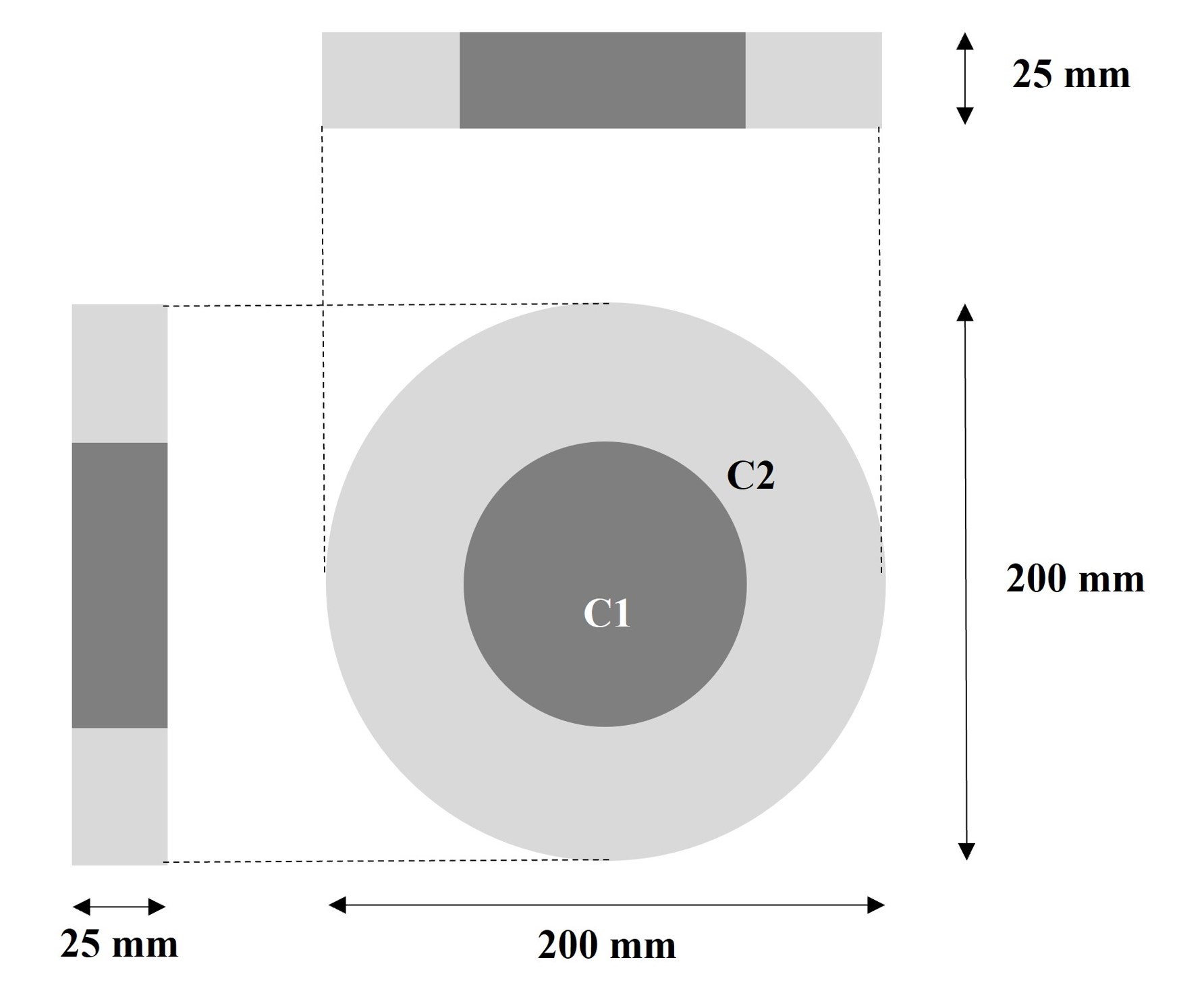
Figure 1 A
numerical phantom containing two types of circular materials. The material parameters were T1 300 ms and T2 50
ms for C1 and T1 800 ms and T2 800 ms for C2,
respectively.
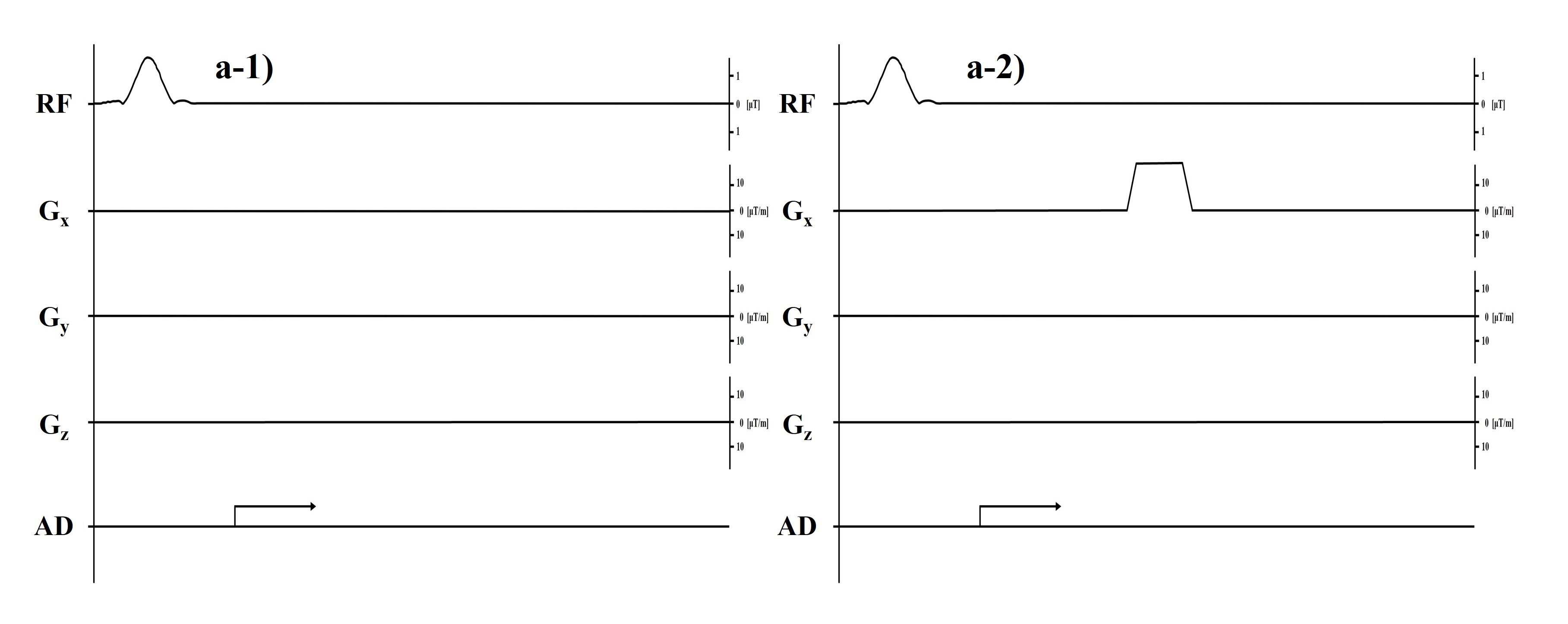
Figure 2 Pulse
sequences for acquiring the data in (a) MR signals. a-1) gradient echo (GrE)
without spoiler gradient, a-2) GrE without spoiler gradient.
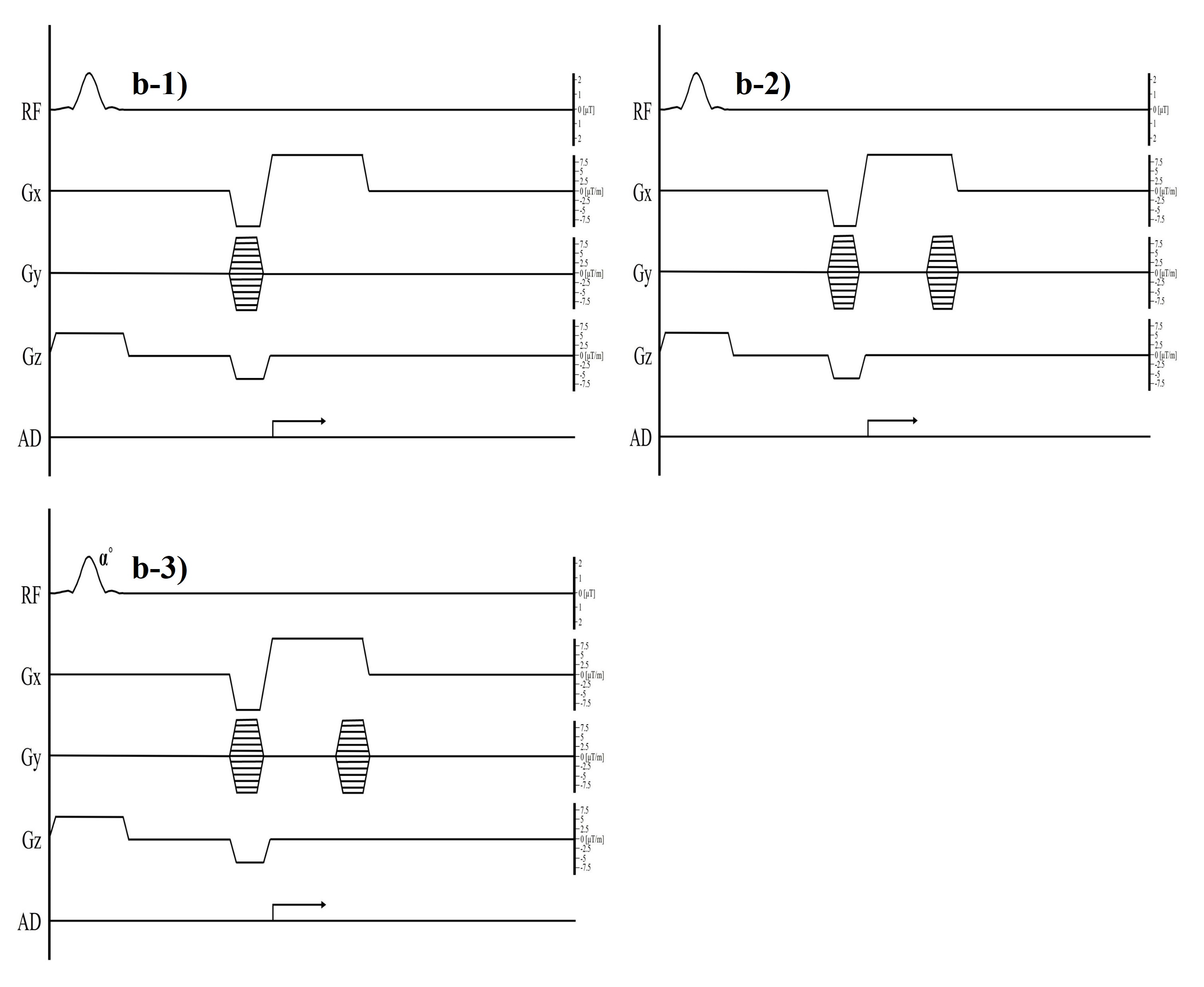
Figure 3 Pulse
sequences for acquiring the data in (b) MR images. b-1) GRASS without phase
encode (PE) rewinding, b-2) GRASS with PE rewinder, b-3) Spoiled GRASS (SPGR).
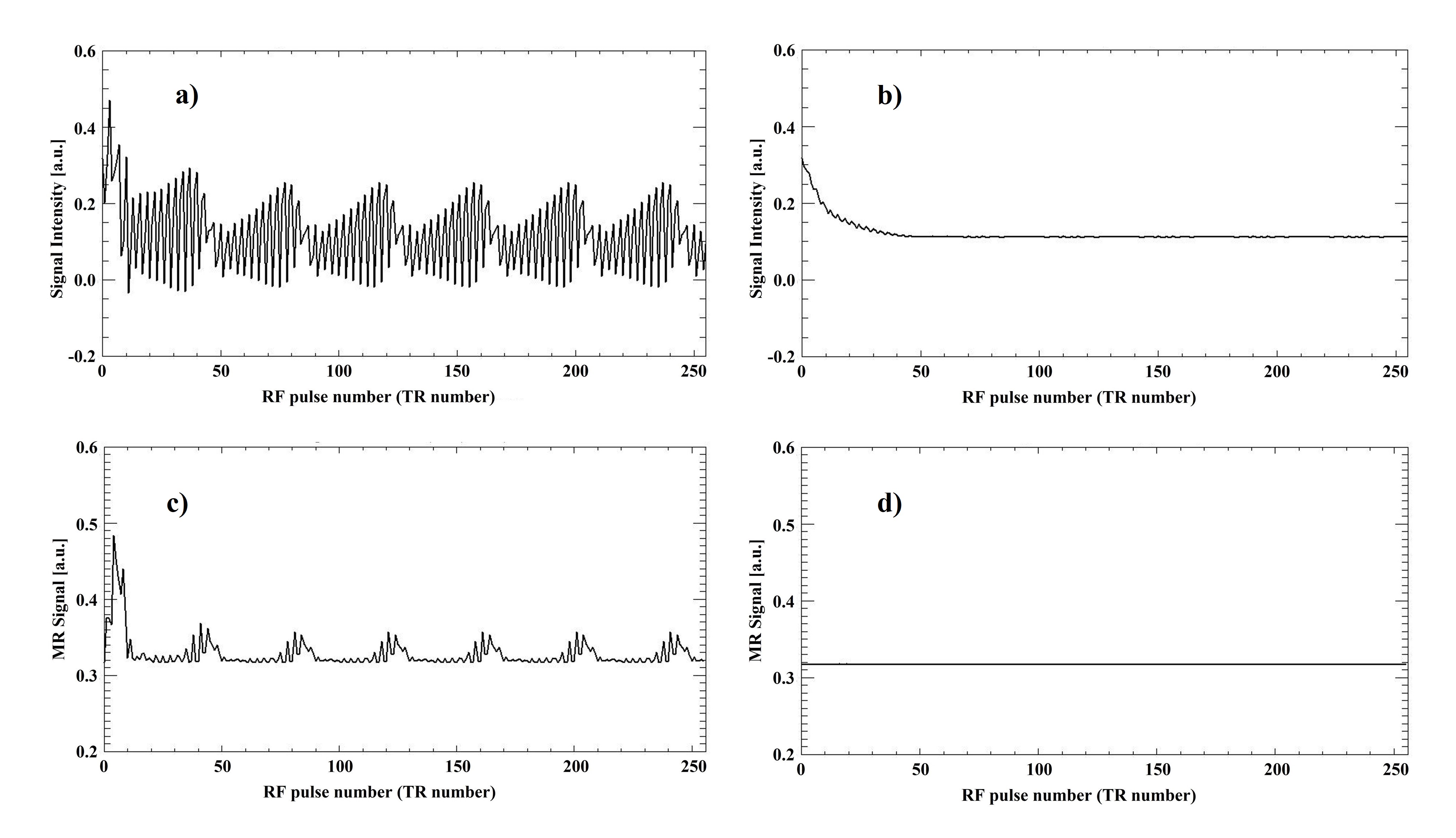
Figure 4 The
changes of FID signals and MR signals with and without the addition of spoiler
gradient. a) FID signal (imaginary part) acquired by GrE without spoiler
gradient, b) FID signal (imaginary part) acquired by GrE with spoiler gradient,
c) MR signal acquired by GrE without spoiler gradient, d) MR signal acquired by
GrE with spoiler gradient, respectively.
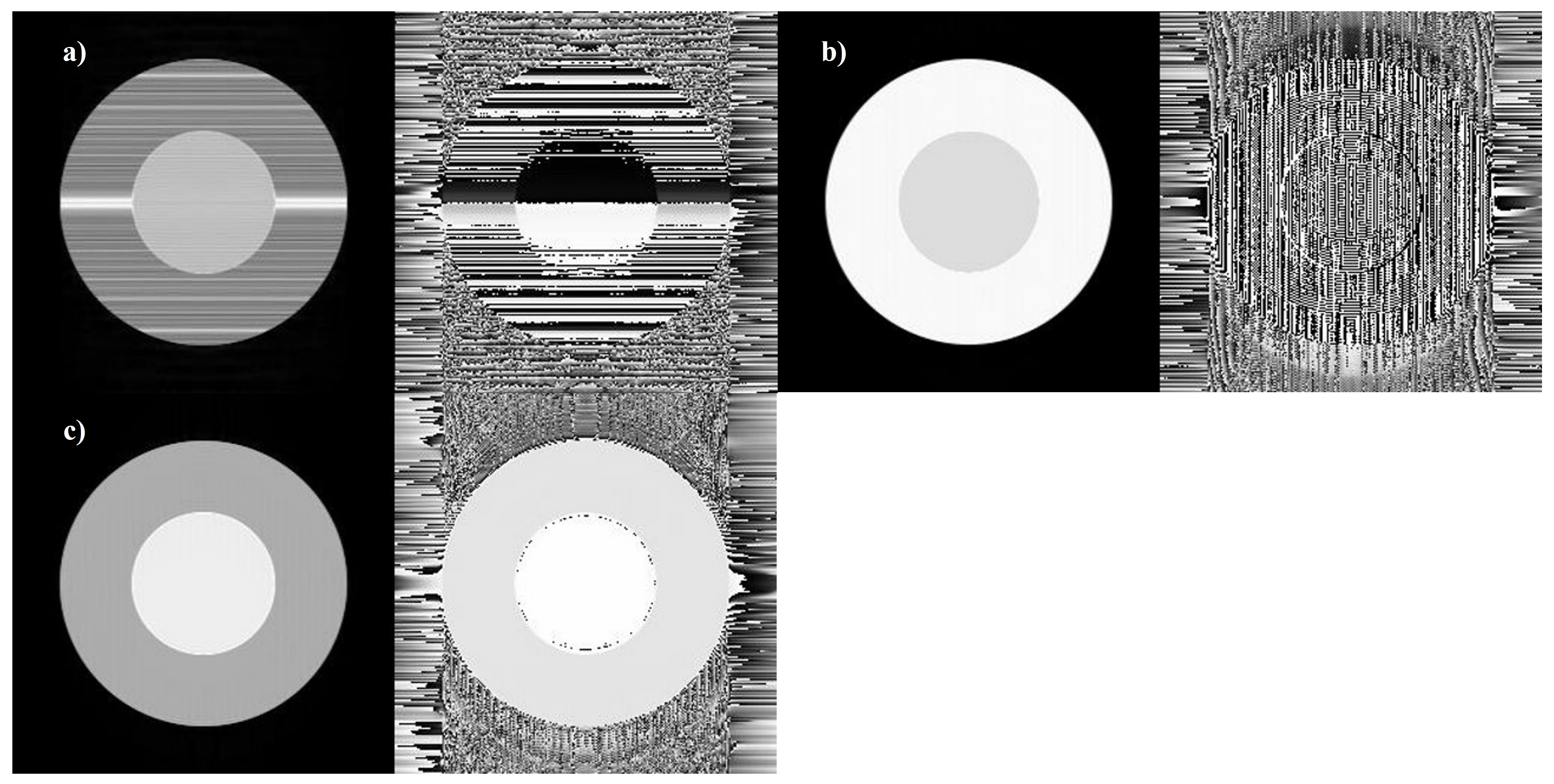
Figure 5 The
changes in magnitude images (left) and phase images (right) with different
imaging methods. a) GRASS without PE rewinding, b) GRASS with
phase encoding (PE) rewinding, and c) Spoiled GRASS (SPGR), respectively.
DOI: https://doi.org/10.58530/2023/2213