2006
Spectrally-encoded multi-spectral imaging (SEMSI) at 0.55T provides improved imaging adjacent to metallic implants1Department of Biomedical Engineering, University of Southern California, Los Angeles, CA, United States, 2Department of Electrical and Computer Engineering, University of Southern California, Los Angeles, CA, United States, 3Stanford University, Stanford, CA, United States
Synopsis
Keywords: Artifacts, Low-Field MRI, Metal
Spectrally-encoded multi-spectral imaging (SEMSI) enables imaging adjacent to metal implants without blurring due to off-resonance, and has been demonstrated at 3T. Here, we demonstrate application of this technique at 0.55T with appropriate adjustments to the spectral resolution and RF pulse bandwidth. A total hip arthroplasty phantom was imaged with SEMSI, turbo spin echo (TSE), and Slice Encoding for Metal Artifact Correction (SEMAC). Experiments demonstrate the feasibility of SEMSI at 0.55T, and examine ΔTE to support multi-echo acquisitions in a single TR.INTRODUCTION:
MRI is an important imaging modality for evaluating patients with metallic implants1. However, these metal implants distort the background magnetic field (proportional to B0), which causes large variations in the frequency spectrum. Resulting artifacts include signal voids and signal pile ups along the slice and readout directions2, which require advanced imaging methods such as view angle tilting and multi-spectral imaging3. One new method, called spectrally-encoded multi-spectral imaging (SEMSI), mitigates these artifacts and has been demonstrated at 3T4.Emerging low-field MRI (<1.5T) is attractive for imaging around metallic implants due to the reduced expected distortion5. Khodaremi et al. have shown that at 0.55T, SEMAC multi-spectral imaging can be applied with a lower SEMAC factor, and therefore reduced scan time6. In this work, we adapt the SEMSI method to 0.55T and test its efficacy compared to standard methods
METHODS:
Experiments were performed using a whole body 0.55T system (prototype MAGNETOM Aera, Siemens Healthineers, Erlangen, Germany) equipped with high-performance shielded gradients (45 mT/m amplitude, 200 T/m/s slew rate). A total hip arthroplasty (THA) phantom with cobalt chrome (CoCr) head and titanium (Ti) stem was scanned using SEMSI, SEMAC, and 2D TSE. Imaging parameters were TE = 25 ms; TR = 3900 ms; matrix size = 256x160; in-plane resolution = 1.2x1.2 mm2; ETL = 7; readout bandwidth = 1028 Hz/pixel; RF bandwidth = 0.5 kHz and 40 slices with slice thickness of 1.5mm for SEMSI; RF bandwidth = 1 kHz and 30 slices with slice thickness of 2mm for SEMAC (minimum slice thickness). 6 phase-encoding steps along the slice direction were used for SEMAC (SEMAC-6).Figure 1 illustrates the fundamental principles of SEMSI. Off-resonant spins from non-target slices are excited by a given RF bandwidth centered at a target slice while the gradient is on. After turning a slice gradient off, the frequency spectrum of a target slice consists of frequency bands coming from various slice locations. With echo shifting, an echo-shifted image represents a single point along the descending portion of FID. The number of samples and (echo shift) are determined according to the Nyquist criterion. MR spectroscopic images are obtained after a Fourier transform along the temporal dimension.
Figure 2 illustrates the SEMSI reconstruction using a set of multiple ∆TE data. With a finite number of ∆TE and a limited range of ∆TE, each ∆f image represents a sampled spectral component for each slice as illustrated in Figure 1.6, which can be used for x-translation and slice shift.
At 0.55T, the spectrum bandwidths of both cobalt chrome and titanium are less 20 kHz. ∆TE for the SEMSI acquisition were [-1000:50:950] us which results in a spectral FOV of 20 kHz with spectral resolution ∆f of 0.5 kHz. To examine the impact of spectral FOV for two different metal materials, Retrospective sub-sampling along ∆TE dimension was by 25%, 50%, 60%,75%, 87.5% from the 0.5 kHz SEMSI data to obtain the spectral FOVs of 15 kHz, 10 kHz, 8 kHz, 5 kHz, and 2.5 kHz with the same ∆f of 0.5 kHz.
RESULTS:
Figure 3 shows 5 central slices of TSE, SEMSI (spectral FOV = 20kHz, ∆f = 0.5kHz) and SEMAC-6 (spectral FOV = 6kHz). The signal distortion caused by titanium stem is negligible in all images at 0.55T, even for TSE. The signal loss and pile up near the CoCr area were reduced in SEMSI and SEMAC, and the quality of SEMSI correction is comparable to SEMAC for the center slice (Slice 21).Figure 4 shows the SEMSI results obtained with different spectral FOVs. Spectral FOV has no effect on the regions near titanium stem (yellow arrow), while the quality of artifact correction near CoCr head starts to degrade starting from a spectral FOV of 5 kHz spectral corresponding to ∆TE of [-1000:200:800] us.
DISCUSSION:
Although there is less susceptibility effect induced by Metallica implant at 0.55T, SEMSI shows promising results and is comparable to SEMAC-6. The total acquisition time could be reduced by 60~75% with a spectral resolution of 0.5 kHz based on the retrospective sub-sampling results for CoCr. The slight off-resonance artifacts and unchanged effect of spectral effect on the Ti stem part is probably due to being parallel to the direction of the main B0.A finer spectral resolution could resolve a more complete spectral distribution and improve the image quality but requires either a longer ∆TE with a fixed number of samples or a larger number of samples with fixed ∆TE. A longer ∆TE limits the spectral FOV to cover the frequency of interest from objects, while a larger number of samples may length the echo train. According to the results in Figure 4, the titanium results in negligible distortion within 2.5 kHz, but the SEMSI quality in nearby regions of CoCr starts to degrade when a spectral FOV of less than 5 kHz (∆TE = 200 us) is adapted. Future work on echo-planar spectroscopic imaging could improve the sampling efficiency but ∆TE should be carefully determined to cover the frequency range of CoCr.
CONCLUSION:
SEMSI is feasible and applicable to imaging around metallic implants at 0.55T. In phantom experiments, SEMSI shows artifacts near metal comparable to SEMAC-6 and reduced compared to TSE.Acknowledgements
We acknowledge grant support from the National Institutes of Health (R01-AR078912) and National Science Foundation (#1828736) and research support from Siemens Healthineers.References
1.Koch KM, Hargreaves BA, Pauly KB, Chen W, Gold GE, King KF. Magnetic resonance imaging near metal implants. J Magn Reson Imaging. 2010;32(4):773-787. doi:10.1002/jmri.22313
2. Hargreaves BA, Worters PW, Pauly KB, Pauly JM, Koch KM, Gold GE. Metal-Induced Artifacts in MRI. American Journal of Roentgenology. 2011;197(3):547-555. doi:10.2214/AJR.11.7364
3.Hargreaves BA, Taviani V, Litwiller DV, Yoon D. 2D multi-spectral imaging for fast MRI near metal: 2D Multi-Spectral Imaging near Metal. Magn Reson Med. 2018;79(2):968-973. doi:10.1002/mrm.26724
4.Yoon D, Lee P, Nayak K, Hargreaves B. Spectrally-encoded multi-spectral imaging (SEMSI) for o -resonance correction near metallic implants. :3.
5. Khodarahmi I, Keerthivasan MB, Brinkmann IM, Grodzki D, Fritz J. Modern Low-Field MRI of the Musculoskeletal System: Practice Considerations, Opportunities, and Challenges. Invest Radiol. 2022;Publish Ahead of Print. doi:10.1097/RLI.0000000000000912
6. Khodarahmi I, Brinkmann IM, Lin DJ, et al. New-Generation Low-Field Magnetic Resonance Imaging of Hip Arthroplasty Implants Using Slice Encoding for Metal Artifact Correction. Investigative Radiology. 2022;57(8):10.
Figures
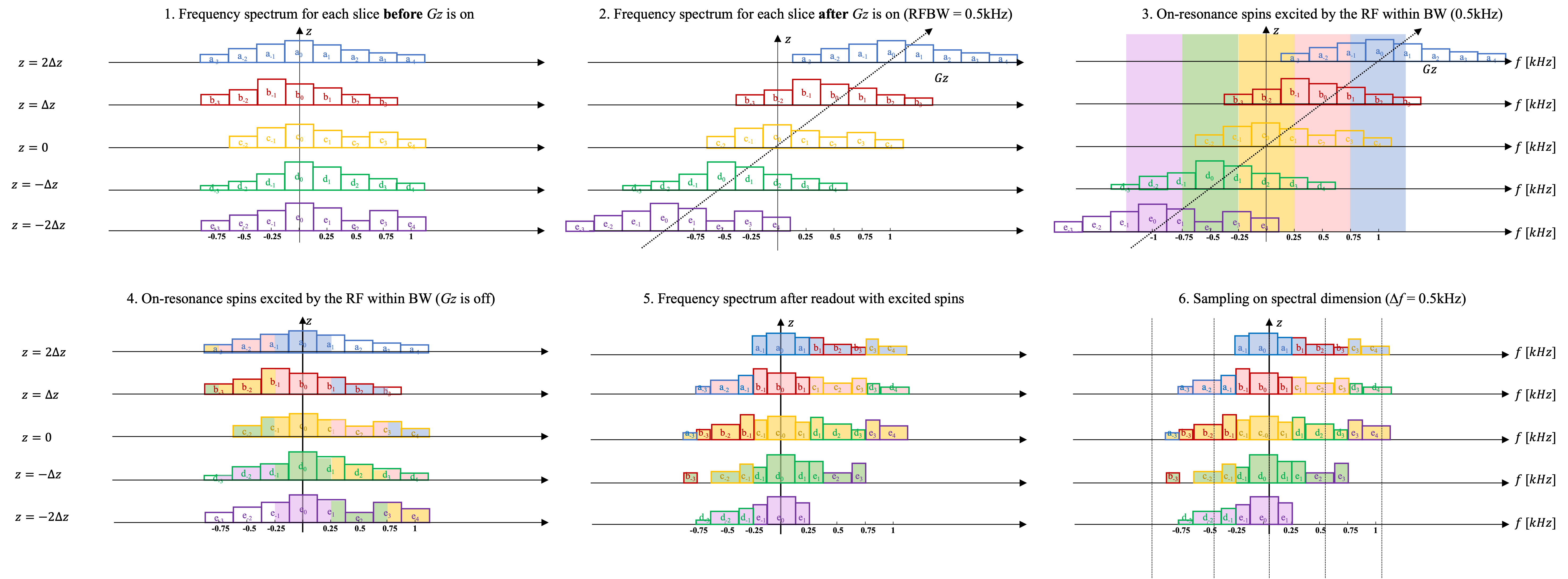

Figure 4. Comparison of SEMSI performance at different spectral FOVs. Central 5 slices are shown. The SNR of the center slice (Slice 21) is 30.4, 29.2, 28.6, 27.1, 27.6, 28.2, and acquisition time is 60, 45, 30, 24, 15, 7:30 minutes for 20 ~ 2.5 kHz SEMSI results, respectively. Distortion correction in regions near the CoCr head (red arrows) improves as a function of spectral FOV and shows marginal improvements after a spectral FOV of 8 kHz. Regions near Ti stem are not affected by different spectral FOVs.