2005
Fast Prospective Motion Correction using Directional Couplers as Motion Sensors
Jason Daniel van Schoor1,2, Mark Gosselink3, Dennis Klomp3, Giel Mens3, Hans Hoogduin3, Wim Prins4, and Tijl van der Velden3
1High Field MRI, UMC Utrecht, Utrecht, Netherlands, 2Utrecht University, Utrecht, Netherlands, 3UMC Utrecht, Utrecht, Netherlands, 4Philips, Best, Netherlands
1High Field MRI, UMC Utrecht, Utrecht, Netherlands, 2Utrecht University, Utrecht, Netherlands, 3UMC Utrecht, Utrecht, Netherlands, 4Philips, Best, Netherlands
Synopsis
Keywords: Motion Correction, Motion Correction, Directional coupler
Motion is a prevalent issue in MRI. Here, we present a fast prospective motion correction (PMC) algorithm using directional couplers as head-motion sensors. The mean reflectances (per volume) of an 8 channel pTx head coil are modelled to head-position recorded by the systems built-in PMC during a calibration scan. Thereafter, the model is used for motion correction at a per RF pulse temporal resolution. Results indicate partial motion correction with error in correcting fast motions due to the necessary presence of filters to remove unidentified low-frequency noise. Mitigating low-frequency noise contributions would allow for less filtering thereby improving dynamic performance.Introduction
The effects of motion in MRI cause image artifacts and corrupt information in advanced MRI applications. Prospective motion correction (PMC) aims to alleviate image artifacts and preserve spin history effects. In this abstract, we provide an update on our previous work of prospective head-motion correction using directional couplers (DiCo’s) as motion sensors [1,2]. Now, acquisition updates can be sent on a per-RF-pulse basis. The reflectance measured during the RF transmit phase from a multi-channel head coil is modelled to head position in a calibration phase. The model is used in subsequent scans to detect and correct for motion. The algorithm to achieve this is termed DiCo motion correction (DMC). DMC has been successfully implemented in the scanner environment and runs as a separate client application.Methods
Experiments were performed using an 8-channel Nova Medical head coil on a Philips 7T MR scanner. The sequence used is a 3D FFE scan (TR/TE=5/1ms, SENSE 4x2, half-scan 75% in the phase encoding directions; 0.8s per volume). DiCo’s in the RF amplifiers record the reflected and forwards signal during every RF excitation. The DMC algorithm requires a calibration phase prior to performing PMC. In this phase the volunteer is asked to move while DiCo data is streamed from the scanner to the DMC where the reflectances are calculated and stored at a per RF-pulse resolution. Low-pass filters are used to filter high-frequency, non-motion associated reflectance components. During this phase, a modified version of the scanner’s built-in PMC algorithm is used to record the rigid-body head position at a per volume temporal resolution. The calibration scan used 500 volumes. After the calibration scan, the mean reflectances over a single volume are modelled to the corresponding position. The models treat the real and imaginary reflectances from each channel as independent variables. A linear model is used to fit the data. The same sequence is used during the motion correction phase. In this phase, the DMC streams DiCo data and computes the position at a per RF pulse temporal resolution (i.e. 5ms). If the position is greater than some threshold, then the DMC sends a volume acquisition update to the scanner. The threshold for sending updates is a detected motion change of 0.5mm translation or 0.5° rotation. Two scans are performed with this motion correction active. In the first scan, the volunteer remains still and in the second scan the volunteer moves in the same manner as was done in the calibration scan. The low-pass filter defines the DMC sensitivity to motion and has been set to 0.5Hz.Results & Discussion
Figure 1 conveys the motion trajectory used during the calibration scan with an experienced volunteer. Figure 2 shows the linear model fitting for each motion to fit well to the data. During a motion correction scan, acquisition updates can successfully be sent every RF pulse for TR>=5ms. Figure 3 presents a snippet of the interpreted motions during the no-motion scan: updates are sent during the pre-pulse phase to reach steady state (dummy pulses) and during the acquisition. Updates during the acquisition are sent due to false-motion interpretations caused by an unidentified low-frequency component in the system. Increasing the cut-off frequency introduces larger false motion interpretations. Figure 4 presents the reconstructed motion trajectory during the motion correction phase per RF pulse. The algorithm is tracking real-motions and correlates well with the trajectory seen in Figure 1. However, with DMC motion correction active, a residual motion is still seen by the scanners built-in PMC – particularly at points of faster, more extreme motion – see Figures 5. This outcome is a result of the low-pass filter. To prevent false-motion interpretations, the filter frequency is set low, this penalizes the DMCs capacity to correctly interpret and correct for fast motions. Additional to this, there is an assumption that a model calibrated at a per volume temporal resolution will be the same as the model that performs best at the per RF pulse temporal resolution. This assumption may not be valid and could be a contributor to the current performance.Conclusion & Outlook
Fast prospective motion correction has successfully been implemented on the scanner with promising results. Efforts to investigate and obviate low-frequency signals in the reflectance could see the method become a successful technique of PMC. Furthermore, investigating calibration sequences which use fewer RF excitations could improve model performance at a per pulse temporal resolution.Acknowledgements
No acknowledgement found.References
[1] Proceedings ISMRM 2020, Abstract 1280.
[2] ISMRM Workshop on Motion Detection & Correction 2022. Abstract 44.
Figures
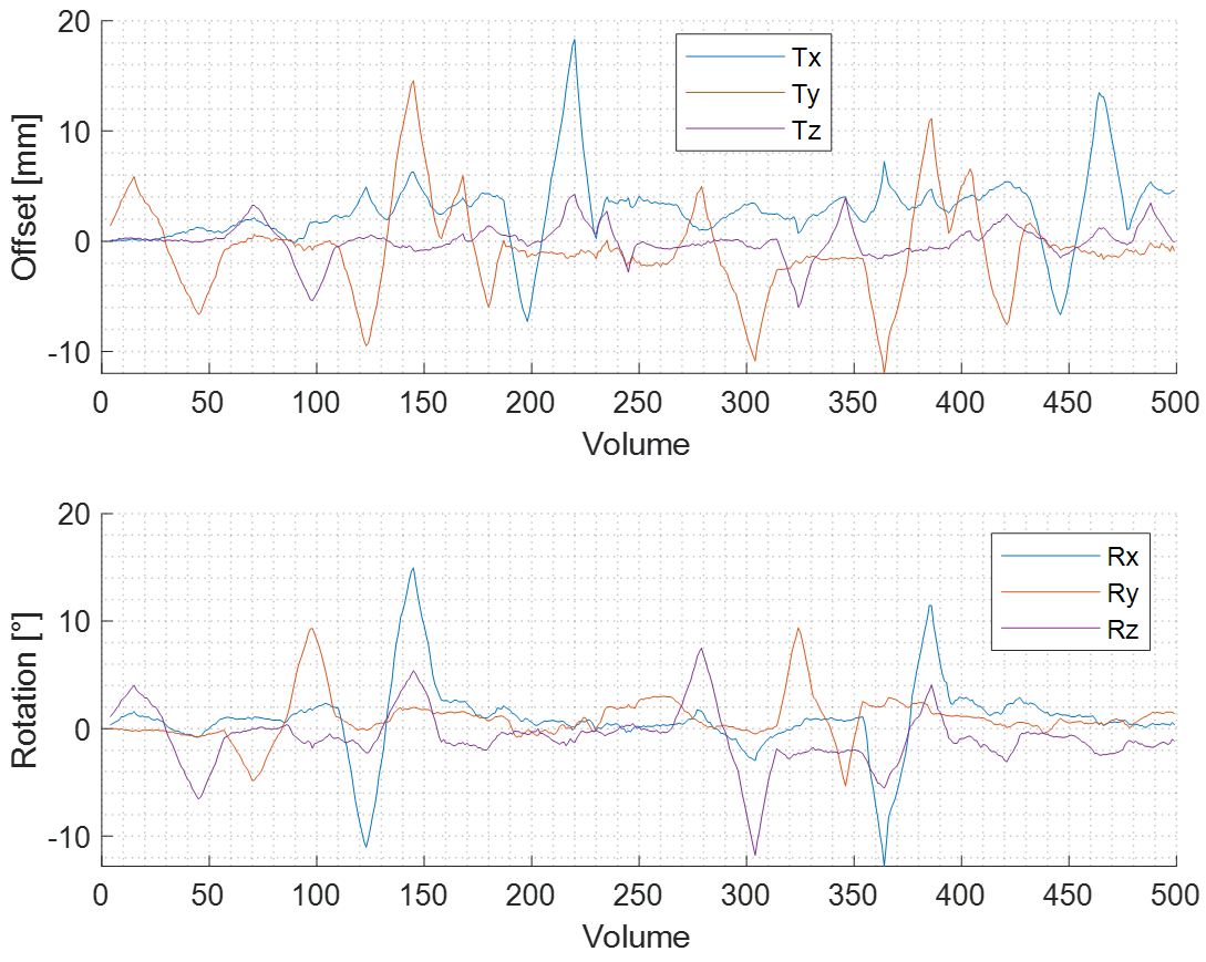
Motion trajectory
from calibration phase. Motions are recorded with respect to
the first volume.
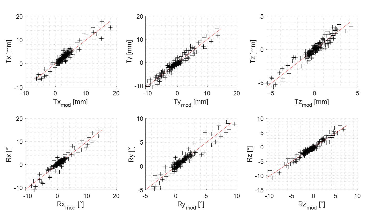
Linear model
performance from calibration phase.
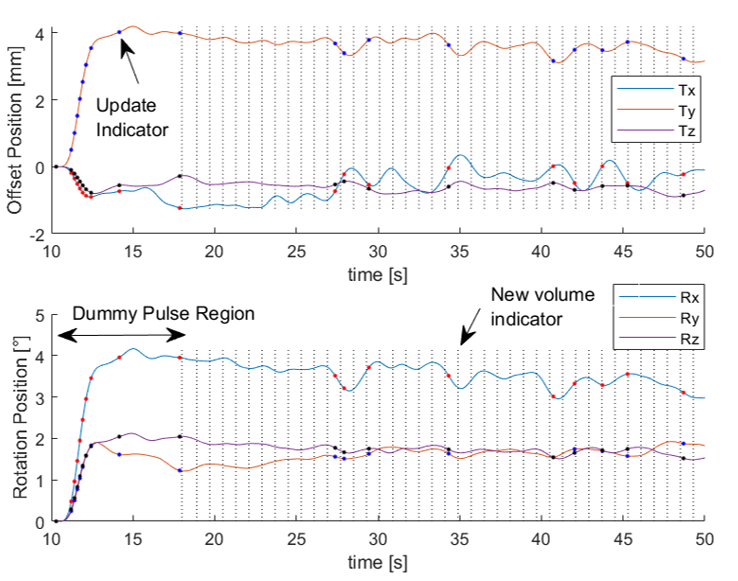
Snippet of motion
correction phase during scan with no-motion. Observe the system takes time to
correct for the position during the initial (dummy) pulses due to the presence
of the low-pass filter.
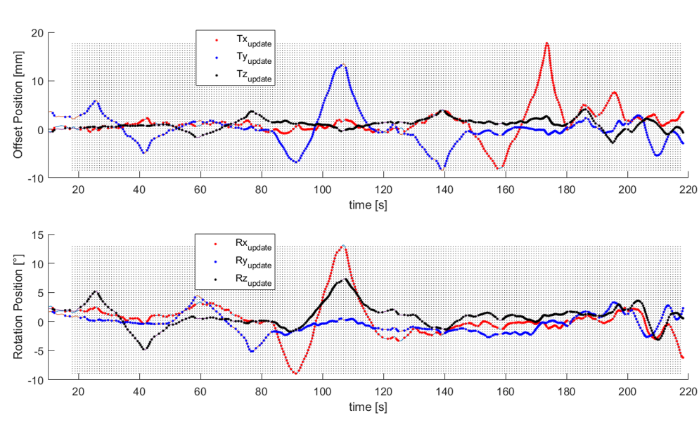
Reconstructed and
corrected for motion trajectory as seen by DMC algorithm during a motion scan.
Note that motions are recorded and updated per RF excitation at a much higher
temporal resolution than the built-in PMC.
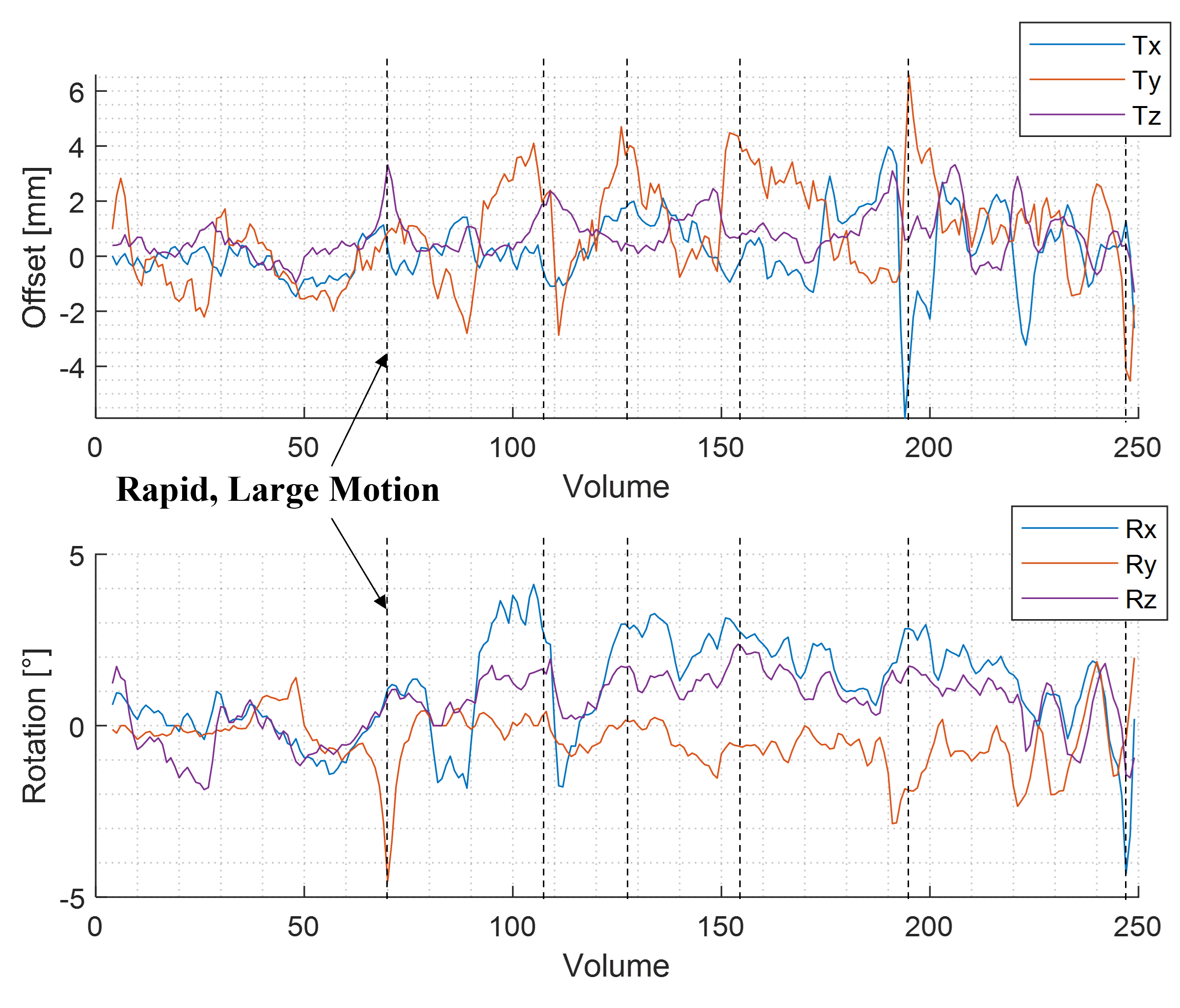
Residual motions
detected per volume. The residual motions are detected with the scanner’s
built-in PMC algorithm running simultaneously to the DMC. Note the motion scale
is much smaller than previously seen in the calibration run.
DOI: https://doi.org/10.58530/2023/2005