1999
Optical position tracking fiducial marker for rigid body motion parameter estimation with high performance1Department of Medical Biophysics, University of Toronto, Toronto, ON, Canada, 2Sunnybrook Research Institute, Toronto, ON, Canada
Synopsis
Keywords: Data Acquisition, Motion Correction, Optical Position Tracking
Optical position tracking (OPT) using fiducial markers is advantageous for data acquisition of rigid body head motion parameters and motion correction in magnetic resonance imaging (MRI). Many opportunities still remain to improve OPT through the development of new devices. A promising prototype OPT marker and analysis pathway are described. The marker through-plane degree of freedom (DOF) precision was enhanced via moiré patterns and stereovision. Precision was assessed using positional and rotational stages in all 6DOF. Initial results strongly suggest that with minimal additional work, the OPT marker will provide excellent performance in a 3 T MRI system.Introduction
Optical position tracking (OPT) using fiducial markers is advantageous for tracking rigid body head motion and for artifact correction in magnetic resonance imaging (MRI), providing high spatiotemporal resolution, MR-compatibility, and precision. For use in prospective or retrospective correction, such tracking should exceed the millimeter spatial resolution typical of most 1.5 and 3 T MRI systems1. Although OPT fiducials already have impressive capabilities, many opportunities for improvement remain, such as concurrent use of other optical methods and multiple camera views2–4, towards increasingly demanding MRI applications. Here we describe promising work assessing the precision of a prototype OPT marker and analysis pathway, prior to validation testing at 3 T.Methods
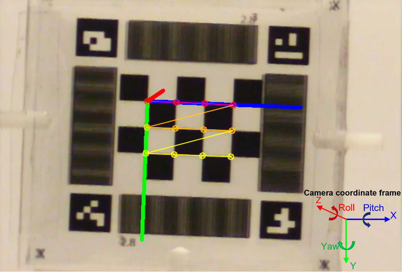
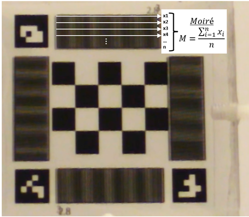
A planar marker (Fig. 1) was fabricated consisting of two laser-printed transparencies adhered to a transparent acrylic plate, for observation by two CCD cameras (WATEC-204CX) with 200 mm focal length lenses at 3 m. Ultimately, the cameras will be wall-mounted at the rear of the magnet room at this distance from magnet isocenter - without encumbering the magnet bore and reducing cost associated with MRI-compatibility. The transparency included a chessboard pattern to track position in six degrees of freedom (DOF) by using corner points to solve the perspective n-point (PnP) problem with the OpenCV library5,6. ArUco symbols were positioned at the four corners of the marker to perform a projective transformation, moving the marker to an undistorted horizontally and vertically aligned planar view such that all marker features had consistent pixel size for analysis.The PnP solution was anticipated to provide high quality outputs for in-plane motion (roll, x, y), but insufficient outputs through-plane (pitch, yaw, z). For the latter 3DOF, the chessboard was augmented with moiré patterns to capture through-plane rotations, and stereovision was adopted to capture z, with constrained optimization planned to enhance precision using the 5DOF already obtained.
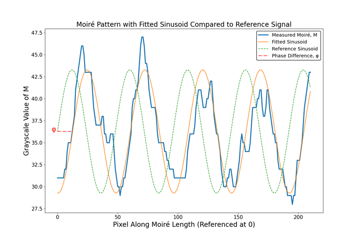
Moiré patterns were added to the marker vertically and horizontally, providing sensitive capture of pitch and yaw based on the linear relationship of pattern phase with rotation7. Moiré phase was assessed by averaging rows of grayscale values through the moiré pattern (Fig. 2). The average signal, M, was then fitted to a sinusoidal function via non-linear least squares to estimate the amplitude, frequency, and phase of M. The phase difference, φ, of M was found by subtracting the fitted parameter from the phase of a reference function (Fig. 3).
Next, stereoscopic tracking was performed via the direct linear transformation (DLT) algorithm by identifying the intersection point of back-projected lines in both camera images8, thus estimating through-plane translation (z). In future work, constrained optimization of the DLT cost function will be investigated using the PnP and moiré estimates to improve estimation of z.
Benchtop testing was performed for each DOF separately using positional and rotational stages (Newport Corp. 423 & 481-A). 5DOF were calculated using one 200 mm focal length camera at 3 m. Z translation was assessed in proof-of-concept stereoscopic tracking with two cameras of 50 mm focal length at 1 m, as matching 200 mm lenses were not available at the time of testing. Measurements were taken at stationary positions during 5 s of recording (~150 frames), with individual pose and moiré estimation at each frame. Translations were measured in 0.1 mm increments from 0-1.5 mm; rotations were measured in 0.5° increments from 0-25°. Moiré measurements involved through-plane rotations in 0.1° increments from 0-2°.
Results
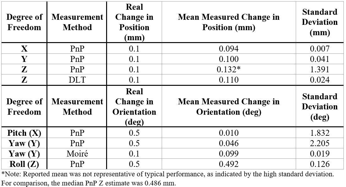
Results are shown in Table 1. As expected, in-plane DOF (roll, x, y) were well-estimated by PnP whereas through-plane DOF (pitch, yaw, z) were poorly estimated with high standard deviation. However, moiré results and z measured via DLT performed notably better than their PnP counterparts, indicating their suitability for through-plane tracking. Moiré performance is visualized in Figure 4.Discussion
These initial results strongly suggest that with minimal additional work, the prototype OPT marker and analysis pathway will provide excellent performance in a 3 T MRI system. A coarse moiré pattern will additionally be needed for in-plane rotations >2°, which are presently ambiguous with the fine moiré because of phase-wrapping. The original plan was to track through-plane rotations using the moiré patterns to refine the PnP pitch and yaw estimates, but this proved infeasible due to the poor quality of these PnP data.In addition, the moiré results can likely be improved even further by improving the marker fabrication procedure, ensuring more uniform adhesion of the transparencies. Z translation results are promising and suggest feasibility at 3 m; although as error increases with the square of distance from the camera, a nine-fold error increase is expected9. Additional research will be required to improve z precision by optimization with 5DOF constraints and to practically mount the marker on individuals for tracking.
Conclusion
A low-cost, high precision OPT tool is proposed here. This tool has the potential to enable research that requires high quality DOF estimates such as characterizing head motion, validating other MR motion correction methods, connecting certain artifacts to types and levels of motion, and more.Acknowledgements
No acknowledgement found.References
1. Maknojia, S., Churchill, N. W., Schweizer, T. A. & Graham, S. J. Resting state fMRI: Going through the motions. Frontiers in Neuroscience 13, (2019).
2. Maclaren, J. et al. Measurement and Correction of Microscopic Head Motion during Magnetic Resonance Imaging of the Brain. PLoS ONE 7, (2012).
3. Lerner, T., Rivlin, E. & Gur, M. Vision-Based Tracking System for Head Motion Correction in FMRI Images. in Advances in Computer Graphics and Computer Vision (eds. Braz, J., Ranchordas, A., Araújo, H. & Jorge, J.) 381–394 (Springer Berlin Heidelberg, 2007).
4. Forman, C., Aksoy, M., Hornegger, J. & Bammer, R. Self-Encoded Marker for Optical Prospective Head Motion Correction in MRI. Med Image Anal 15, 708–719 (2011).
5. Bradski, G. The OpenCV library. Dr. Dobb’s Journal 25, 120–125 (2000).
6. Chikop, S. A. et al. Automatic motion correction of Musculoskeletal MRI using DSLR camera. Magnetic Resonance Imaging 48, 74–79 (2018).
7. Armstrong, B. S. R., Verron, T., Karonde, R. M., Reynolds, J. & Schmidt, K. RGR-6D: low-cost, high-accuracy measurement of 6-DOF pose from a single image. (2007).
8. Hartley, R. & Zisserman, A. Multiple View Geometry in Computer Vision. (Cambridge University Press, 2004).
9. Hossack, W. Topic 10: Stereo Imaging. (2006).
Figures