1828
Optical camera calibration to implement various marker-based motion correction techniques in open geometry 0.5 T upright scanner1SPMIC, University of Nottingham, Nottingham, United Kingdom
Synopsis
Keywords: Motion Correction, Motion Correction, Marker-based, calibration
Open MRI scanner improves patient comfort but allows movement during scanning. Hence, implementation of MoCo techniques is crucial to maximize image quality. Here, we established a method to use a standard commercial optical motion tracking set-up in an Open MRI scanner. The optical system has been calibrated to provide tracking measurements in the image reference frame. Then, a simple phantom movement was tested and corrected using NUFFT algorithm in BART.Introduction
Open MRI allows MR images to be acquired whilst the patient is positioned in a wide range of physiologically relevant body poses1. This increases the participant’s comfort, particularly for claustrophobic subjects and children, but tends to lead to increased motion2.The aim of this abstract is to propose a calibrated system for monitoring motion in the scanner using a standard commercial optical motion monitoring system, and to test it in retrospective motion correction of rigid body motion of a phantom.Methods
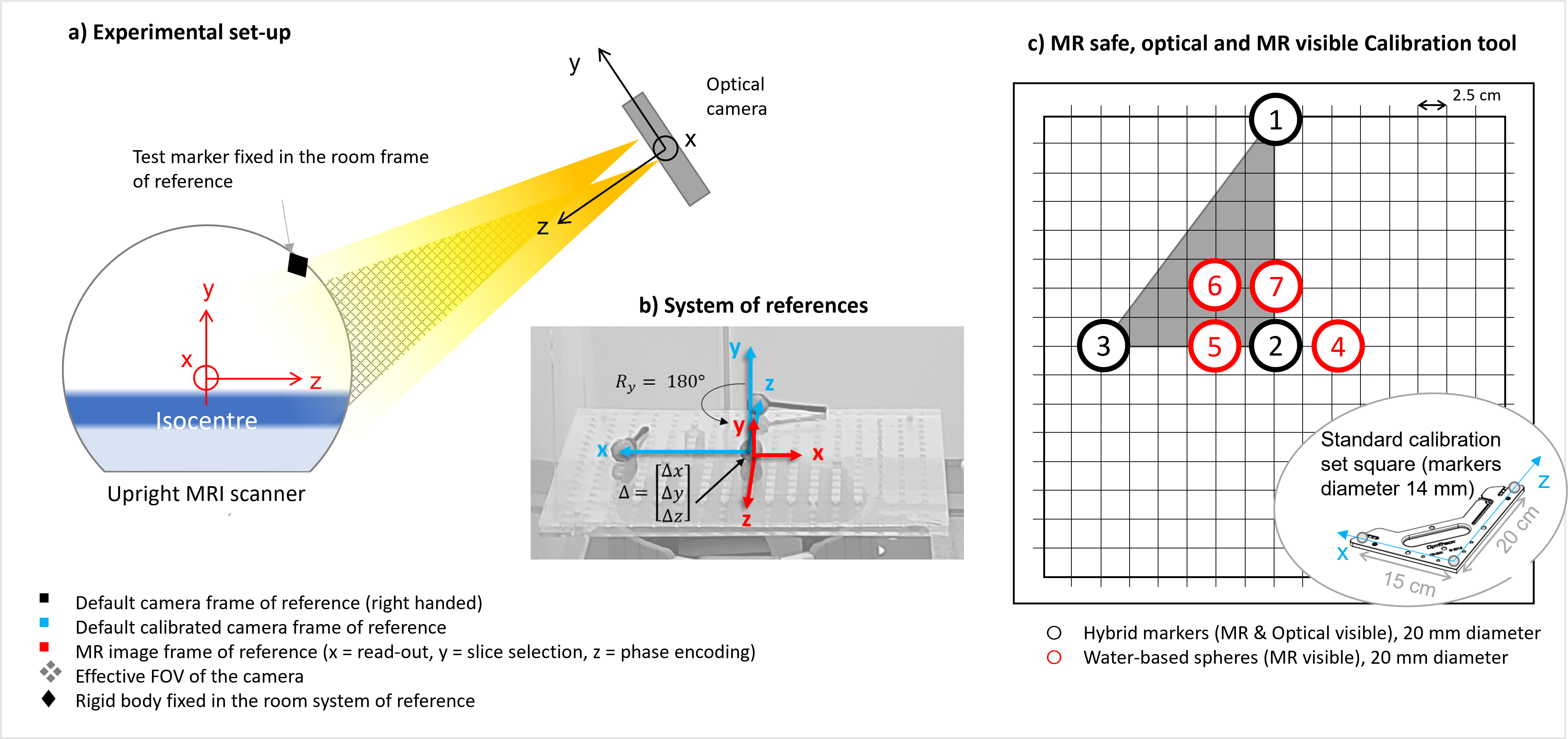
Motion was monitored using a dual optical motion monitoring camera (https://optitrack.com/cameras/v120-duo/) placed 2m above and in front of the 0.5T Paramed scanner (Fig.1a). To implement MoCo the tracking measurements have to be referred to the Frame of Reference (FoR) of the scanner gradients. However, it is difficult to align the camera calibration system directly on isocentre, so a two-stage process was adopted.The default FoR of the camera has its origin at the physical centre of the camera system. First, this FoR is translated to the FoR of a standard calibration set-square (Fig.1c) using the camera’s software. We created a hybrid MRI/optical phantom, mimicking the calibration set-square, including MRI visible markers (water-filled and optical-reflective d=2cm markers, located within 6cm of each other, remaining within the scanner’s DSV Fig.1c).
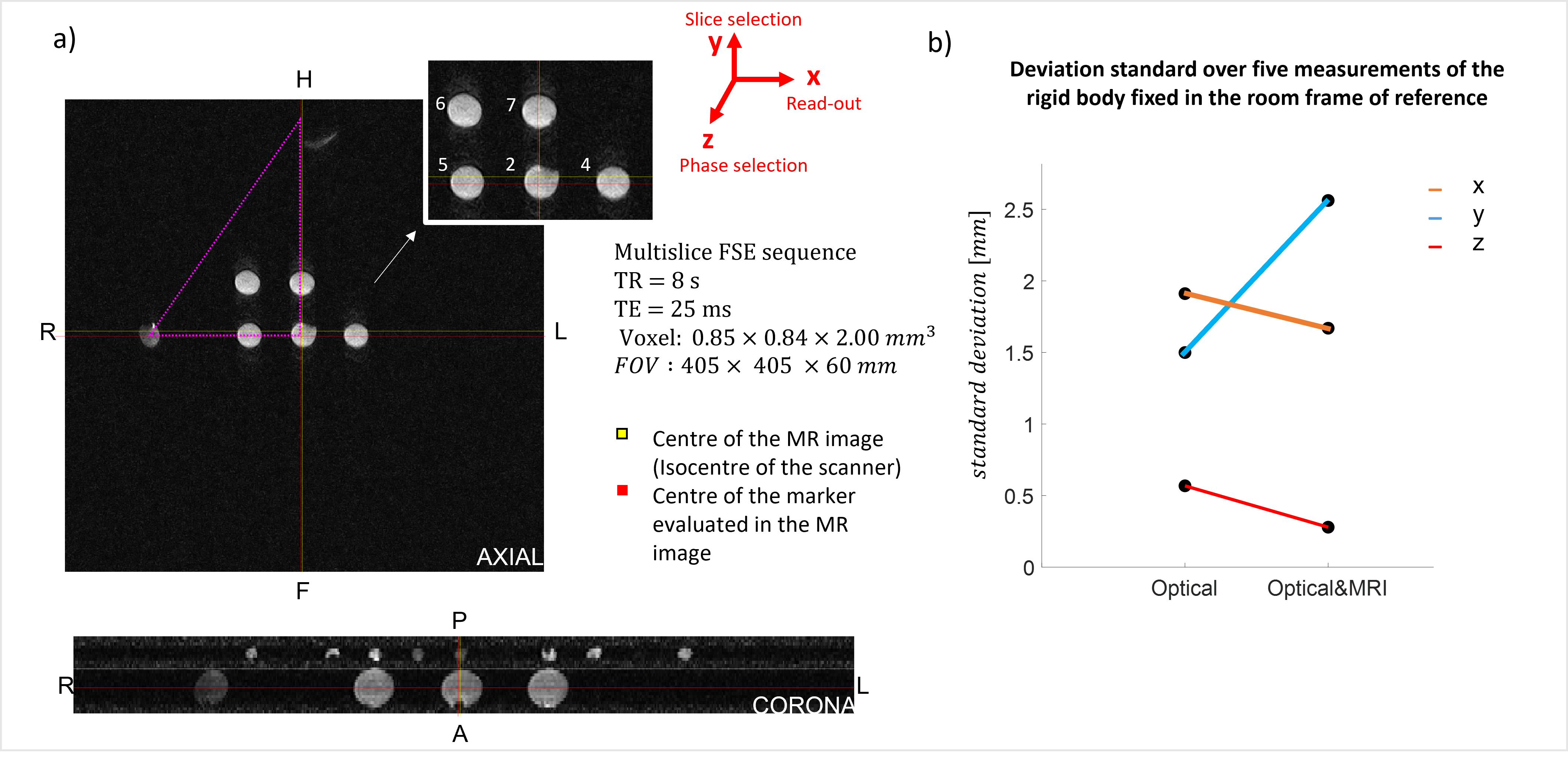
This hybrid set-square was placed close to the scanner isocentre3, horizontally on the scanner bed. Next, the FoR of the set-square FoR was shifted to the FoR of the gradients, by imaging the hybrid set-square using a surface receiver coil (multislice FSE, TR=8s, TE=25ms, 0.85×0.84×2.00mm3 voxel) and determining the shift between the set-square FoR origin and the gradients’ isocentre.
The calibrated camera was used to determine the position of a test-marker placed on the side of the scanner, in the FoR of both the set-square and the scanner (Fig.1). The set square was repositioned, the calibration process was repeated and the position of the test-marker was determined 5 times to assess the precision of the final calibration.
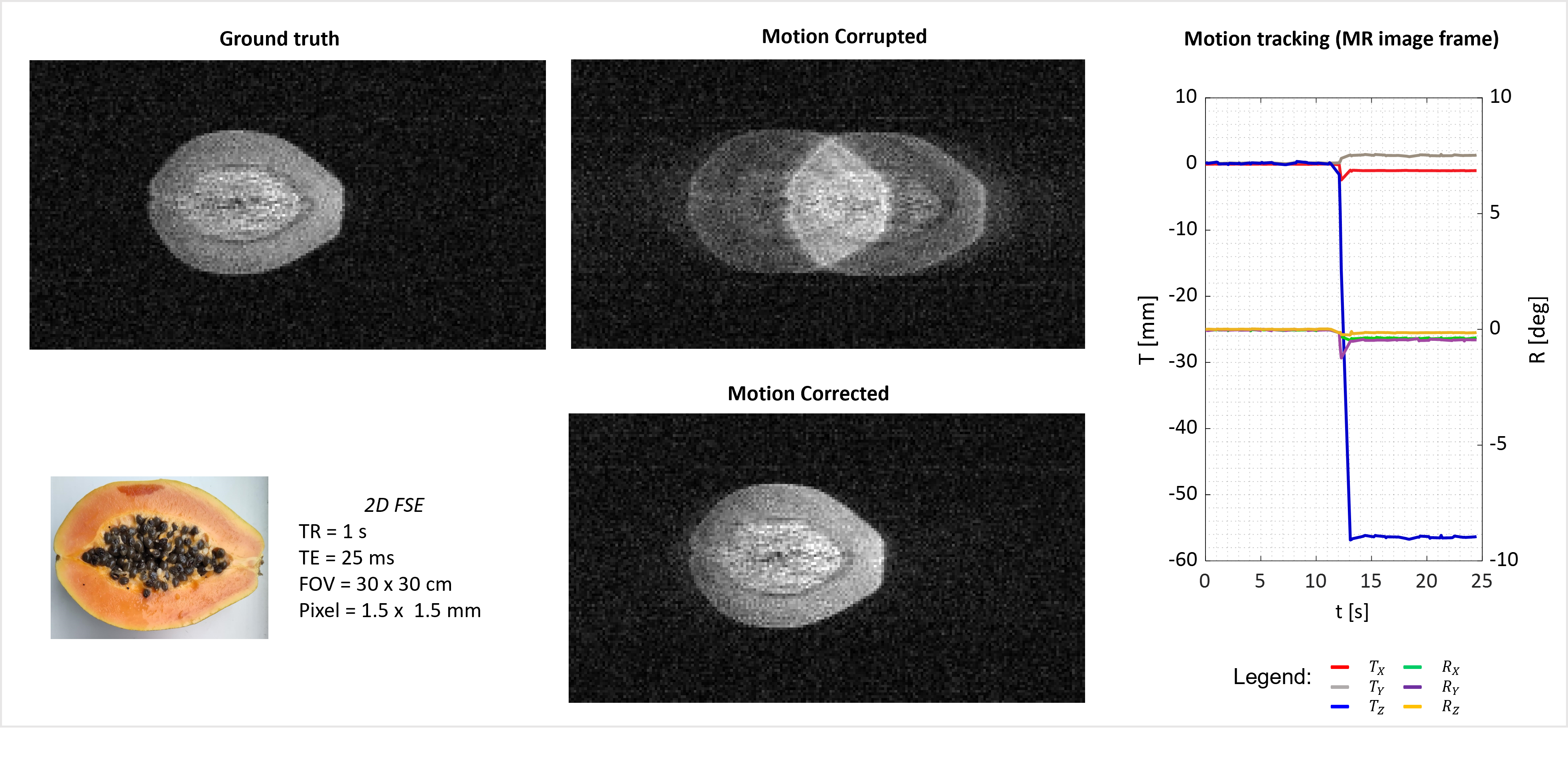
To test the use of the camera and calibration for retrospective MoCo, a set of three reflective, optically visible markers were fixed to a small support marker board (d~8cm) to form a rigid body, needed to track motion. The test object was a papaya fruit, wedged tightly in a plastic box coupled to the marker board. Papaya was chosen to be small enough to be moved within the region of the MRI scanner that is free from distortions4. We tested pure translations in the phase encoding direction (Tz). MR images were acquired using 2D FSE (TR=1s, TE=25ms, 1.5x1.5x10mm3 voxel size) at the initial position and during motion. Simultaneous recording of tracking data and the timing of the RF pulses was achieved using Matlab-controlled NI-DAQ board. With this system, a single marker board could be tracked at minimum rate of 8ms. In post-processing, this information allowed to identify the motion parameters relevant to each k-space line and to implement RMC in BART5,6.
Results
The camera calibration was successfully performed 5 times. Fig.2b shows the standard deviation of the test-marker location in the set-square FoR (which depends on its location) and the scanner (which should be constant). This was smaller in the FoR of the scanner in the x and z axes, corresponding to the read-out and phase encoding directions of the MRI scan (resolution=0.8mm). The precision was worse in the y direction, corresponding to slice selection direction (slice thickness=2mm).The calibrated camera was used to correct Tz motion sucsefully using RMC pipeline (Fig.3).
Discussion
The Open MRI scanner allows direct optical calibration of the camera into a FoR defined by its calibration set square. However, it is experimentally challenging to have this directly aligned with the scanner system of reference, the FoR to whom the tracking measurements have to be referred to in order to perform MoCo. The use of a hybrid optical/MRI visible marker allowed translation of the FoR of the camera into the frame of reference of the scanner with good accuracy in the imaging plane. In the future, 3D imaging will be used to determine the position of the set square in the scanner FoR accurately in all directions.The static and gradient fields of the open scanner are only uniform and linear within a 120mm diameter spherical volume (DSV) [4]. Successful calibration relies on the fact that the hybrid marker lays within that volume. Similarly, the object used to test the RMC was only moved within this 120mm DSV. Future work will focus on incorporating field inhomogeneities and gradient nonlinearities into the MoCo.
The sampling rate of the optical camera, and so of the tracking, is determined by the number of rigid bodies monitored. For one marker board the sampling rate was 120Hz, likely sufficient for most MRI pulse sequences. However, it significantly increases if more marker boards are tracked e.g. to monitor non rigid motion of the human torso (down to 20Hz for tracking 5 rigid bodies). This needs to be considered for the future development of PMC technique.
Conclusion
This work represents a step forward implementing the first fully functioning motion correction technique for open geometry MRI scanner.Acknowledgements
I’d like to thank my research group for the amazing team working done to achieve these results.References
1. https://www.asgsuperconductors.com/progetto/mropen
2. Zaitsev M et al. Motion artifacts in MRI: A complex problem with many partial solutions. Magnetic Resonance in Medicine 2015;42(4):887-901
3. Zahneisen B, Lovell-Smith C, Herbst M, Zaitsev M, Speck O, Armstrong B, Ernst T. Fast noniterative calibration of an external motion tracking device. Magn Reson Med. 2014;71(4):1489-500. doi: 10.1002/mrm.24806
4. Mistry D J, Gowland P A, Bowtell R W, Mougin O, Glover P. Characterising the Magnetic Field Inhomogeneity in Open MRI at 0.5T using a Screened Coil NMR Probe Design. Abstract #1204, presented by: Laura Bortolotti
5. Fessler J A. On NUFFT-based gridding for non-Cartesian MRI. J Magn Reson. 2007;188(2):191-5. doi: 10.1016/j.jmr.2007.06.012
6. Berkeley Advanced Reconstruction Toolbox (BART)
Figures