1777
Optimization and Construction of a Low-Field MRI System Using Permanent Magnets1University of Toronto, Toronto, ON, Canada, 2University of British Columbia, Kelowna, BC, Canada
Synopsis
Keywords: Low-Field MRI, Magnets (B0)
A low-field tabletop spoke-and-hub permanent magnet array was constructed and assessed for homogeneity as a B0 field. Spatial encoding in the x and y directions was achieved by tilting the hubs relative to one other to generate a linearly increasing field in the tilt direction. A non-array RF coil was designed and optimized for low field strengths, where the signal-to-noise ratio is limited by the weak signal from the sample. The optimized coil design was tuned and matched to the resonant frequency of the spoke-and-hub magnet.Introduction
In pre-clinical research settings, fundamental to basic health research, MRI imaging data can be both important and difficult to obtain. The expense and complexity of the diagnostic imaging system can limit the access and application of MRI as a research and assessment tool to large institutions and clinical settings. Low-field MRI is of increasing interest to bridge these gaps and reduce demand for the limited high-field systems.1 The development of cheap, portable low-field MRI systems, capable of low-resolution imaging would expand the availability of non-invasive MRI evaluations. This tool could expand the availability of imaging in remote or otherwise inaccessible locations.We aim to construct a low-field MRI system using primarily open-source or off-the-shelf components. To this end, a main magnet assembly was constructed using a spoke-and-hub design2 and the field characterized. Gradients in x and y were expected when the hubs were tilted relative to one another3 and this was supported by measurements in our system. Finally, several RF coil designs were considered and optimized for use with this system based on the method of Blasiak et al.4
Methods
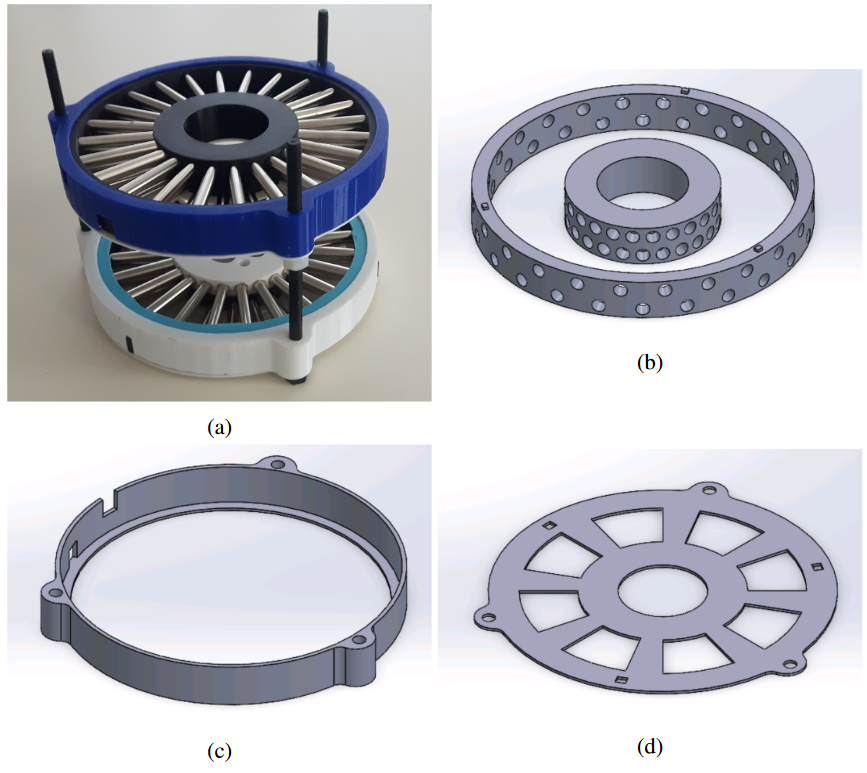
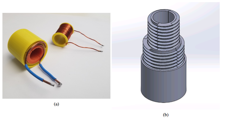
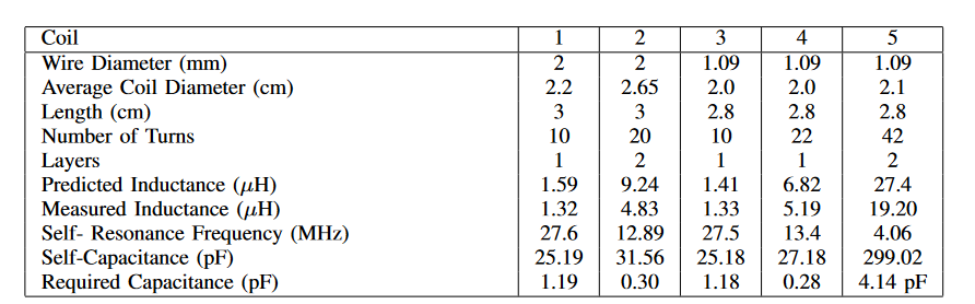
Main Magnet Construction and Optimization: The main magnet (Figure 1a) was constructed of two magnetic hubs with 3D printed chassis. Each hub consisted of two layers of 24 ¼ in diameter, 2 in N42 neodymium magnets for a total of 96 magnets. A chassis design with separate inner and outer rings (Figure 1b) was selected for ease of assembly. The strong repulsive force at the centre of the hub caused projectile risk during assembly in early prototypes with fixed outer shields, so a rotating shield (Figure 1c) was added to prevent magnets from being ejected. A locking plate (Figure 1d) was used to secure the shield and to allow the hubs to be accurately aligned. The hubs were levelled and the field was mapped using a TLE493 magnetic field sensor and a manual mapping tool at 1.6 mm intervals in the horizontal direction and 3 mm intervals in the vertical direction.RF Coil Construction and Optimization: At 5 MHz, a solenoid has previously been found to have the highest average maximum field intensity, the highest maximum overall field intensity, the highest Q factor and the highest homogeneity of several tested coil geometries.5 Therefore, five solenoidal RF coils (two examples shown in Figure 2a) were constructed using two different sizes of copper wire (1.09 mm diameter and 2 mm diameter). Formers were designed and printed for each coil with an example shown in Figure 2b, and the coils analyzed using a DG8SAQ 3SE VNA with a 1.6 cm diameter test tube water phantom.
Results
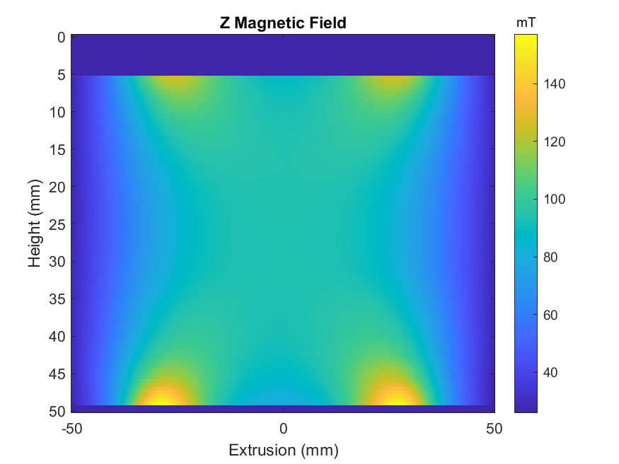
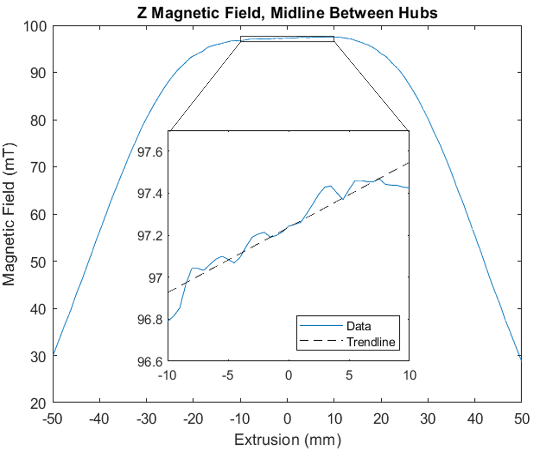
The central field of the main magnet was found to be 93.87 mT, giving a resonance frequency of 3.998 MHz (see Figure 3). When the hubs were offset by ~1 mm, a linear gradient of 3 mT/m was generated, as shown in Figure 4.The predicted and measured properties of the tested RF coils are presented in Table 1. The Q factor of coils 2 and 4 was observed to peak near the target frequencies, therefore these coils were tuned and matched to the resonance frequency of the main magnetic field. These designs demonstrated Q factors of upwards of 10 000 when loaded with a water phantom. The coil resistances of the two coils were estimated at 0.415 Ω for coil 2 and 0.642 Ω for coil 4.
Discussion
The horizontal imaging region of highest homogeneity is approximately 2 cm in width and 1 cm in height. The predictable gradients in x and y demonstrate a low-power method of generating spatial encoding in two of three directions. Based on the geometry of the spoke-and-hub magnet, a simple Helmholtz coil that lies in the plane of the magnets is suggested to generate the z gradient.If the B1 field extends into regions where the gradients are nonlinear, it can cause artifacts in the resulting images,6 however, too-short a coil sacrifices B1 homogeneity. A 3 cm long solenoid is within the linear region of the main magnetic field, which is about 4 cm horizontally, and allows for shortening of the linear region when tilt-induced gradients are applied.
In both wire sizes tested, the 20-turn coil performed optimally at the target frequency. This supports previous assertions that 20-30 turns for a 2 cm diameter coil at 4 MHz generates the highest Q factor.7 Given the low signal intensities at low field strengths, the optimal coil must have the lowest resistance, and the resistance is increased by 50% by decreasing the wire thickness. Therefore, the 20-turn, 2 mm diameter coil is the optimal design for this system. The extremely high Q factors observed with the coils in isolation imply that even in the presence of an RF system, high Q factors can be achieved by this coil.
Conclusion
Our design demonstrates the feasibility of an off-the-shelf, low-field MRI system that could be adapted for use in educational kits and pre-clinical research settings. We also present an optimized RF coil design for use with a spoke-and-hub permanent magnet B0 field at 4 MHz with Q factors in the 1000s in isolation.Acknowledgements
This research was supported by the Canadian Foundation for Innovation John R Evans Leaders Fund, Natural Sciences and Engineering Research Council of Canada Discovery Grant, and UBC Okanagan Undergraduate Research Award.References
1. L.L. Wald, P.C. McDaniel, T. Witzel, J.P. Stockmann, and C.Z. Cooley, J Magn Reson Imaging 52, 686 (2020).
2. I.A. Kuang, Equivalent-Charge-Based Optimization of Spokes-and-Hub Permanent Magnets for Hand-Held MR Imaging, Thesis, Massachusetts Institute of Technology, 2020.
3. I. Kuang, J. Stockmann, E. Adalsteinsson, and J. White, in (ISMRM, 2021), p. 3100.
4. B. Blasiak, V. Volotovskyy, C. Deng, and B. Tomanek, Magnetic Resonance Imaging 27, 1302 (2009).
5. M. R and S.Y. Huang, in 2021 IEEE International Symposium on Antennas and Propagation and USNC-URSI Radio Science Meeting (APS/URSI) (2021), pp. 1669–1670.
6. C.Z. Cooley, J.P. Stockmann, T. Witzel, C. LaPierre, A. Mareyam, F. Jia, M. Zaitsev, Y. Wenhui, W. Zheng, P. Stang, G. Scott, E. Adalsteinsson, J.K. White, and L.L. Wald, Journal of Magnetic Resonance 310, 106625 (2020).
7. C.-N. Chen and D.I. Hoult, Biomedical Magnetic Resonance Technology (A. Hilger, Bristol ; New York, 1989).
Figures