1776
EM shielded spiral RF coil design for array coil decoupling at ultra-low field MRI1Radiology and Biomedical Imaging, Yale University, New Haven, CT, United States, 2Biomedical Engineering, Yale University, New Haven, CT, United States
Synopsis
Keywords: RF Arrays & Systems, RF Arrays & Systems
We introduced a new RF coil made with Moebius cable and RF shield bowl that can be tuned with relatively low capacitance and has good isolation between the coils at low field. B1 amplitude, isolation between the coils, and SNR of the NMR signal of the proposed coil were compared with reference coils (made with copper wire and Moebius cable without an RF shield). Both bench measurements and MR experiments have demonstrated that this coil performs well as part of a low field coil array.Purpose
Receive array coils are widely used in high field MRI and may also improve SNR at low field. Furthermore, array coils may allow a reduction in scan time by allowing undersampling of k-space. Despite these advantages, array coils are not widely used in low-field MRI for a range of reasons. To tune the coil at low frequency, higher capacitance is required for both tuning and matching capacitors. Thus, either more expensive (barely available) capacitors or a large number of capacitors connected in parallel must be used1. Many of the well-known decoupling methods, with the exception of geometrical decoupling methods, do not work well due to both the unusual capacitance and inductance at low field1, 2. In this work, we introduced a new RF coil that can be tuned with relatively low capacitance and has good isolation between the coils.Methods
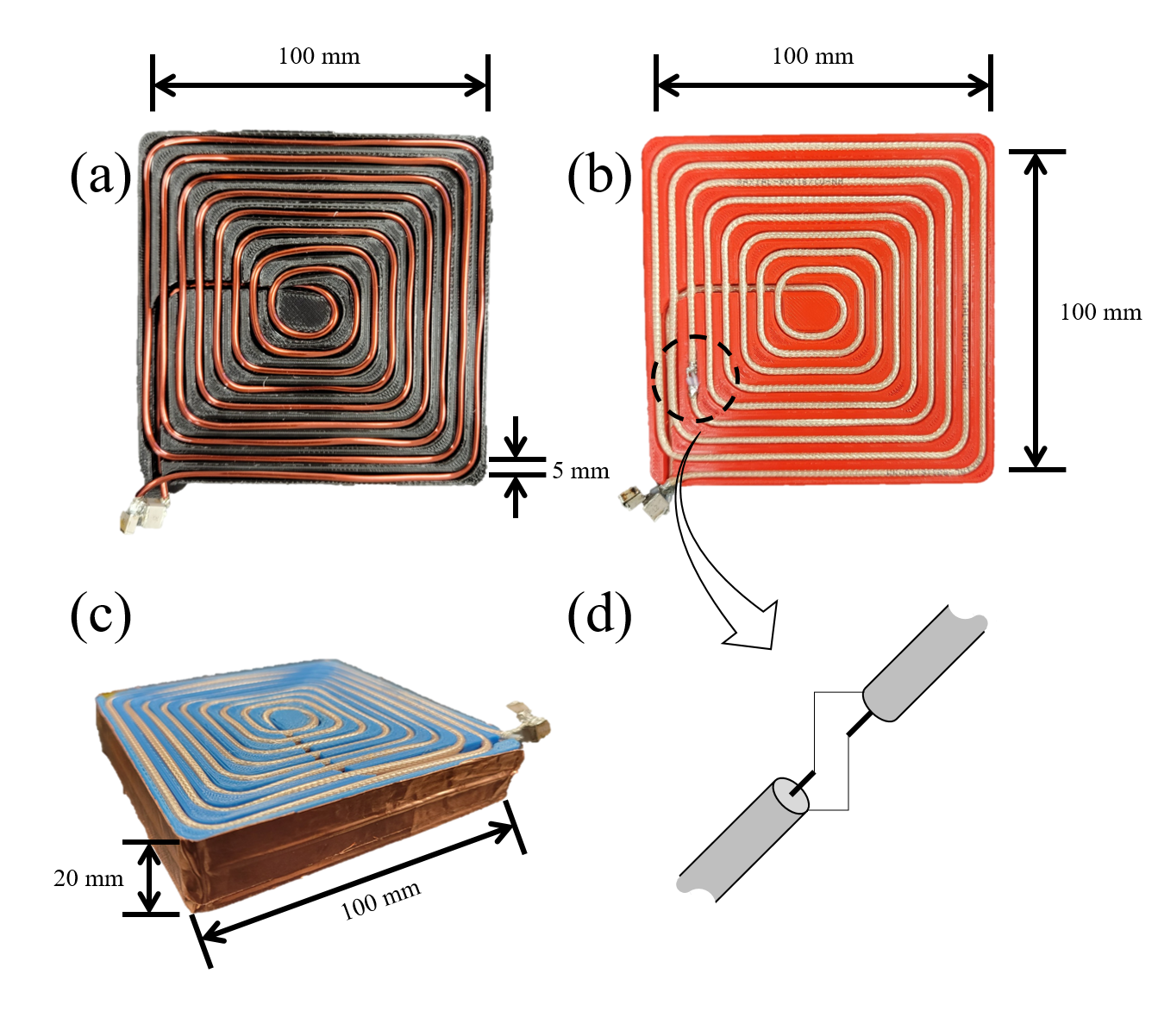
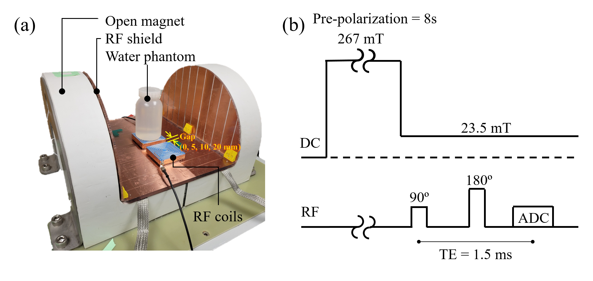
Figure 1 shows the spiral loop coils3, 4 made with (a) copper wire (4.6 mm diameter) and (b, c) co-axial cable (RG-316). For the spiral coil with co-axial cable, the inner conductors of each cable end are connected to the outer conductors of the opposite cable end as shown in Fig. 1d5. Using this Moebius loop configuration increases the inductance of the coil, which in turn allows the coil to be tuned with a smaller capacitance. Notably, the tuning capacitance to tune the coil at 1 MHz for the copper wire loop and Moebius loop were 7,700 pF and 1,720 pF, respectively. Figure 1c shows the EM shielded spiral coil. The coil is the same as the co-axial spiral coil in the Moebius loop configuration, except that it is shielded on five faces with copper tape. Compared to the unshielded case, higher capacitor values were required (1,900 pF and 680 pF for tuning and matching, respectively), but this can help reduce coupling between the loops. To verify this, S21 between two elements of each coil design was measured and compared using a vector network analyzer. Axial B1 maps of the coils for single channels were also measured with a 3-axis probe interfaced with a commercial 3D printer6. All the bench measurements were performed on the table-top MRI system which includes an RF shield on the surface of the magnet (Fig. 2a)7. Spin-echo signal was acquired with three different spiral coils under different coil distance conditions using the table-top MRI system (Fig. 2b). For each scan, Tx power was adjusted to apply proper 90/180 degree pulses.Results
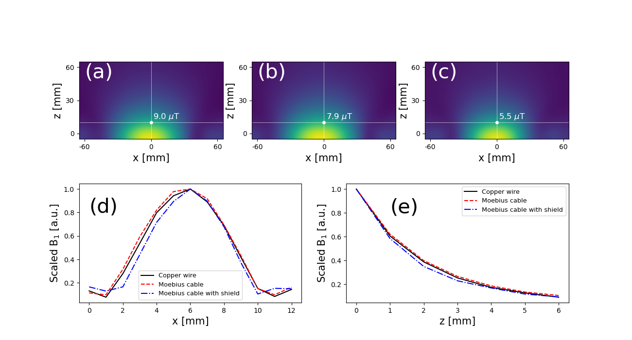
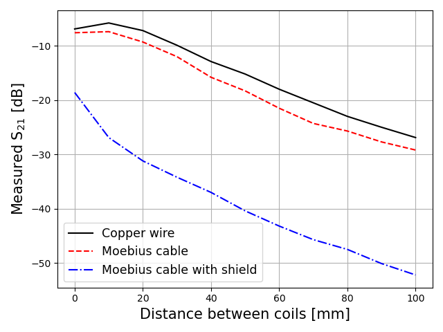
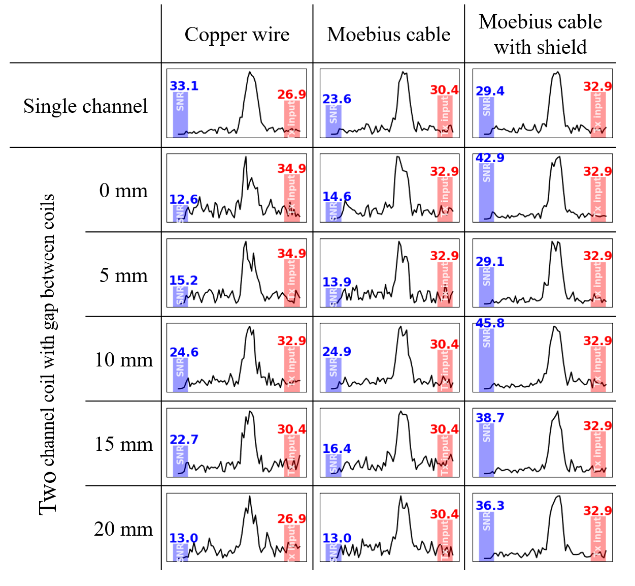
Figure 3 shows the measured B1 maps associated with the the three spiral coil designs shown in Figure 1. The measured field profile was qualitatively similar in all cases, but the B1 amplitude was highest for the copper wire (Fig 1a) and lowest with the EM shield (Fig 1c). Figure 4 shows the measured S21 values between the coil elements. With the EM shield, isolation between the coils is improved by more than 20 dB in most cases (more than 11 dB improvement with 0 distance between the coils) compared to other methods. Figure 5 shows the spin-echo signal acquired with spiral coils under different coil distance conditions. Despite larger B1 values in the two unshielded coils, which are typically associated with higher sensitivity as well as better RF encoding patterns, Figure 5 shows that unshielded coils have significantly lower SNR than the design that implements a shielded bowl. In addition, higher Tx input power was required for the unshielded coils for low coil separations. In contrast, the required input power for the shielded coil does not change with coil separation.Discussion
We have introduced a spiral coil made with a Moebius cable and RF shield at the bottom and side walls. This coil configuration helps reduce the coupling effect between adjacent elements in an array without the need for other decoupling methods. A further advantage is that lower capacitance was required for coil tuning and matching. Thus, trimmer capacitors can be used for coil tuning and matching. Both bench measurements and NMR experiments demonstrated that this coil design coil performs better when it is used for multi-channel array coil. As shown in Fig. 3, adding an RF shield has little effect on the shape of the B1+ field, but requires higher input power for the same B1 amplitude. However, as shown in Fig. 5, when used as an array coil, there is no change in transmission efficiency because it is not affected by the surrounding environment. This is in contrast to unshielded coils, which require higher input power due to the coupling effect. In addition, the SNR of the signal acquired with shielded coil was not reduced by adding an adjacent coil element, whereas it was significantly decreased for other coil designs. Both bench measurements and MR experiments have demonstrated that this coil performs well when used as an array coil for low field MRI.Conclusions
It was demonstrated using both bench measurements and NMR experiments that the bowl-shielded spiral Moebius coil outperforms unshielded coils in terms of decoupling the array coil elements. This method can be effectively used for array coil development, particularly at the low-field MRI system.Acknowledgements
No acknowledgement found.References
1.B. de Vos, J. Parsa, Z. Abdulrazaq, W. M. Teeusisse, C. D. E. Van speybroeck, D. H. de Gans, R. F. Remis, T. O’Reilly, and A. G. Webb, “Design, characterisation and performance of an improved portable and sustainable low-field MRI system,” Front. Phys., vol. 413, 2021.
2. C. J. Cooley, J. P. Stockmann, B. D. Armstrong, M. Sarracanie, M. H. Lev, M. S. Rosen, and L. L. Wald, “Two-dimensional imaging in a lightweight portable MRI scanner without gradient coils,” Magn. Reson. Med., vol. 73, no. 2, pp. 872-883, 2015.
3. K. N. Kim, Y. B. Kim, and Z. H. Cho, “Improvement of a 4-channel spiral-loop coil RF coil array for TMJ MR imaging at 7T,” J. Korean Soc. Magn. Reson. Med., vol. 16, no. 2, pp. 103-114.
4. S. Shen, Z. Xu, N. Koonjoo, and M. S. Rosen, “Optimization of a close-fitting volume RF coil for brain imaging at 6.5 mT using linear programming,” IEEE Trans. Biomed. Eng., vol. 68, no. 4, pp. 1106-1114.
5. O. Aluf, “Moebius loop antenna system stability analysis under parameters variation,” IEEE COMCAS, pp. 1-5, 2017.
6. Y. Ha, K. Selvaganesan, S. Hosseinnezhadian, B. Wu, K. Hancock, G. Galiana, and R. T. Constable, “Automatic 3D B1 field mapping using 3D printer and digital oscilloscope for gradient-free MRI system,” in Proc. 29th Annu. Meet. Int. Soc. Magn. Reson. Med., Virtual meeting, May 15-20, 2021.
7. R. T. Constable, C. Rogers III, B. Wu, K. Selvaganesan, and G. Galiana, “Design of a novel class of open MRI devices with nonuniform B0, field cycling, and RF spatial encoding,” in Proc. 27th annu. Meet. Int. Soc. Magn. Res. Med., Montreal, Canada, May 10-13, 2019.
Figures