1775
Demonstrating the Scalability of Spokes-and-Hub Magnet Designs1Electrical Engineering and Computer Science, Massachusetts Institute of Technology, Cambridge, MA, United States, 2Institute for Medical Engineering and Science, Massachusetts Institute of Technology, Cambridge, MA, United States
Synopsis
Keywords: Low-Field MRI, Low-Field MRI
The easily constructed Aubert ring-inspired “spokes-and-hub” magnets show promise as a topology for handheld MR imaging, particularly for educational purposes. In this paper we show the scalability of the spokes-and-hub design, and associated tools and RF signal processing, by scaling up the magnet. Constructing a 2x larger magnet yields a volume large enough to potentially image a finger (with which we hope to inspire students). We used our simulator to design and optimize the magnet topology, then constructed it from off-the-shelf small bar magnets, and verified its fields by direct Hall-effect measurements as well as indirectly through spin echoes.Introduction
“Spokes-and-hub” magnets, initially inspired by Aubert’s ring pair, are easily designed and optimized using very fast charge-based simulation, easily constructed from off-the-shelf bar magnets, and easily scaled to a variety of applications1-4. In this paper, we demonstrate this scalability by designing a magnet whose volume is large enough to image a finger—a key concern for use in educational settings. Below we show our 2x magnet, compare simulation and Hall-effect measured fields, and present final verification by generating spin echoes on both water phantoms and a human finger.Methods
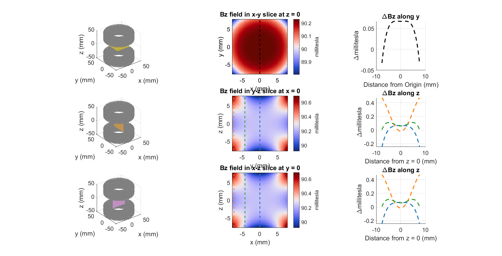
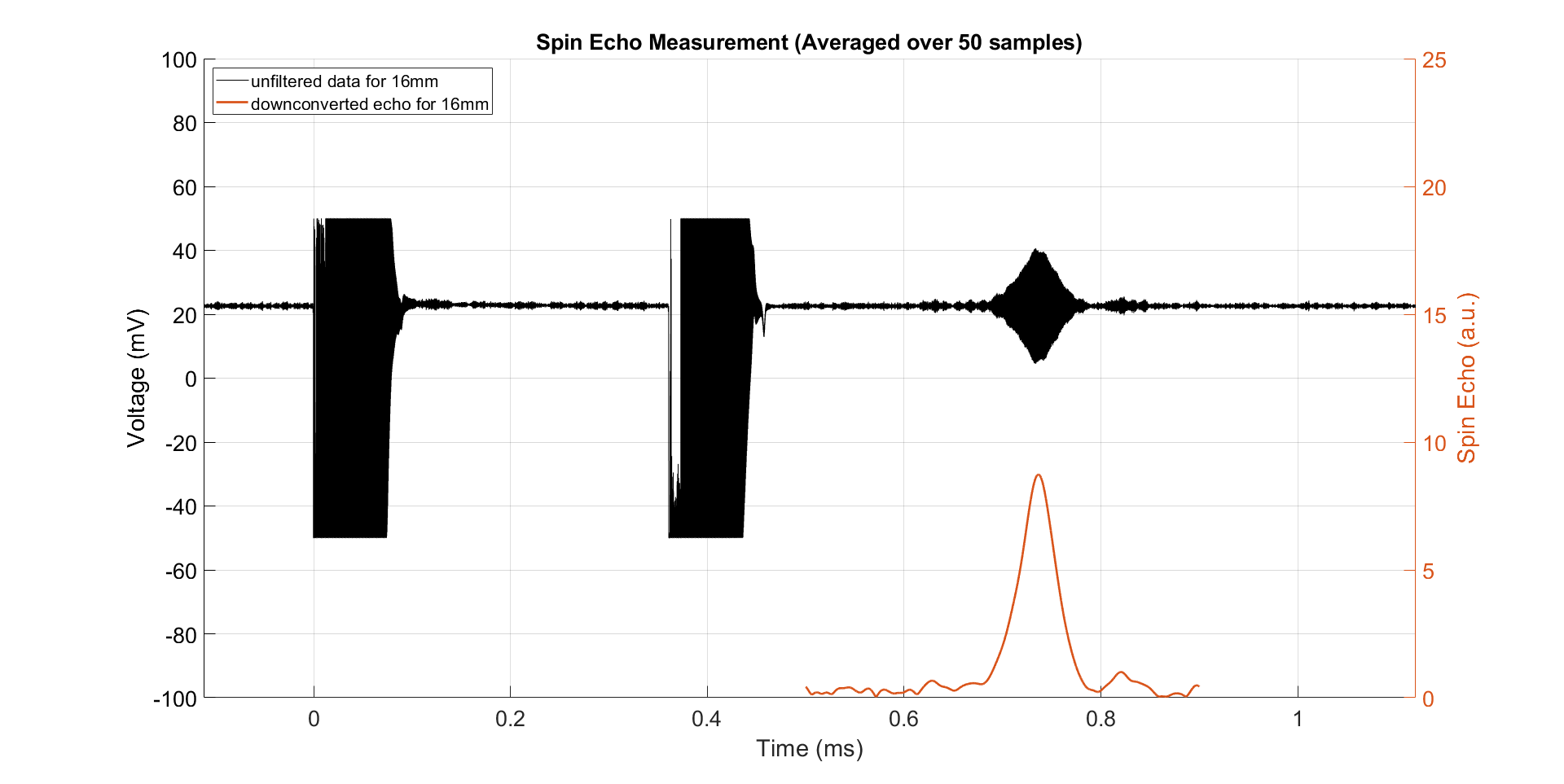
The first prototype of the spokes-and-hub magnet topology contains 32 bar magnets, extending radially around a 34.16mm diameter opening with a center point field of approximately 191.7 mT5. Our goal is to approximately double the size of the current magnet infrastructure, creating a spokes-and-hub ring pair with an inner diameter of 66mm that contains 50 rectangular bar magnets per ring. The magnets used in the smaller topology are 12.7 x 3.175 x 25.4 mm (1/2 x 1/8 x 1in), magnetized through the 25.4 mm (1in) thickness direction, whereas the magnets used in the larger topology are 25.4 x 3.175 x 12.7 mm (1 x 1/8 x 1/2in), magnetized through the 12.7mm (1/2in) thickness direction (both bar magnets from K&J Magnetics). Using the same MATLAB simulator as used for the first handheld MR prototype, we obtained the optimized separation distance for the two rings (36.65mm) along the z-axis to minimize field inhomogeneities around the center of the magnet. Plots of the simulated z-directed static B0 magnetic field in the x, y, and z=0 planes are shown in Figure 1 (B0 = 90 mT)5. The ring pairs were then constructed from 3D printed PLA, and the commercially available bar magnets were assembled in the same spokes-and-hub configuration as the functional scaled-down model. To verify that the assembled magnet matched the simulation plots, we used the ALS31300 Hall-effect sensor to measure the magnetic field along the diameter at the z=0 plane of the structure. Once confirmed that the center field matched the simulation calculations, the identical signal chain hardware from the previous spokes-and-hub magnet MR was used to excite the test phantoms. The signal chain consists of the Teensy 4.0 to send dithered, modulated square wave 90- and 180-degree pulses (with a duration of ~12 microseconds and a 50 kHz bandwidth) and the STHV800 8-channel ultrasound pulser to drive these signals6. A single solenoid coil (with an inductance of 0.627 microhenries for both coils), which has been tuned to match the magnet’s Larmor frequency (~3.845 MHz), was used for transmit and receive. We were able to successfully generate spin echoes from the magnet when exciting a 16mm diameter test tube of water.Results
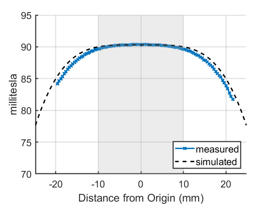
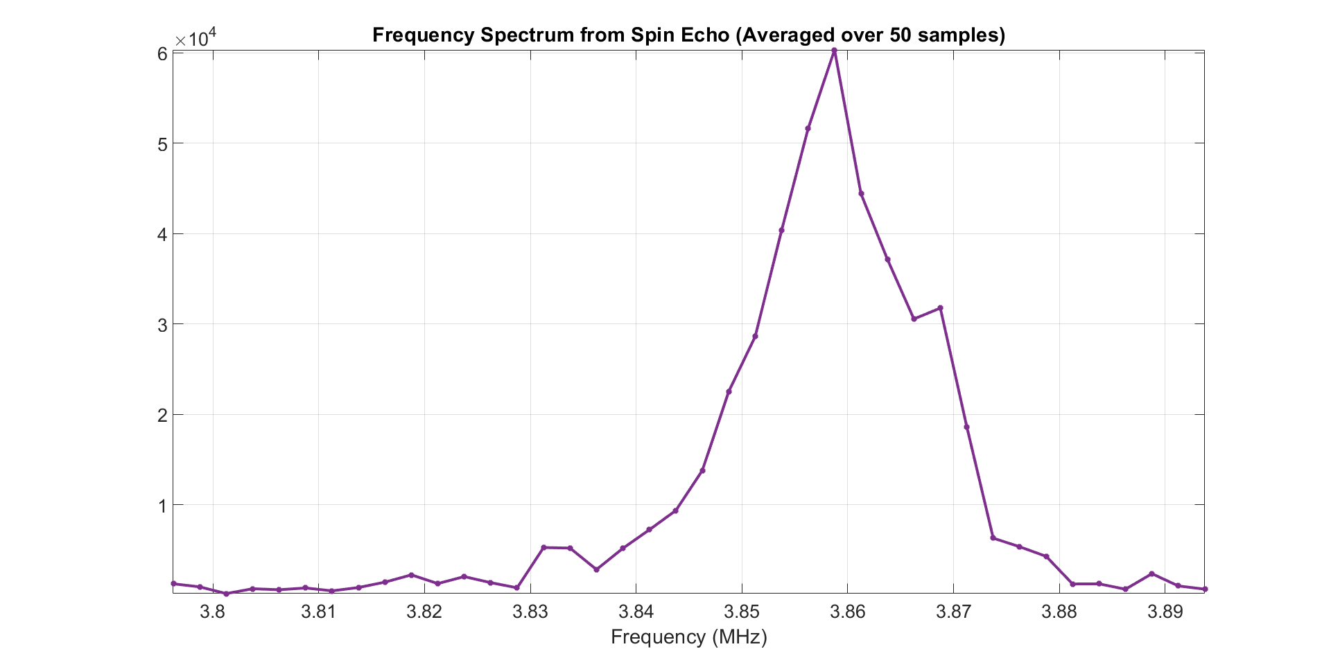
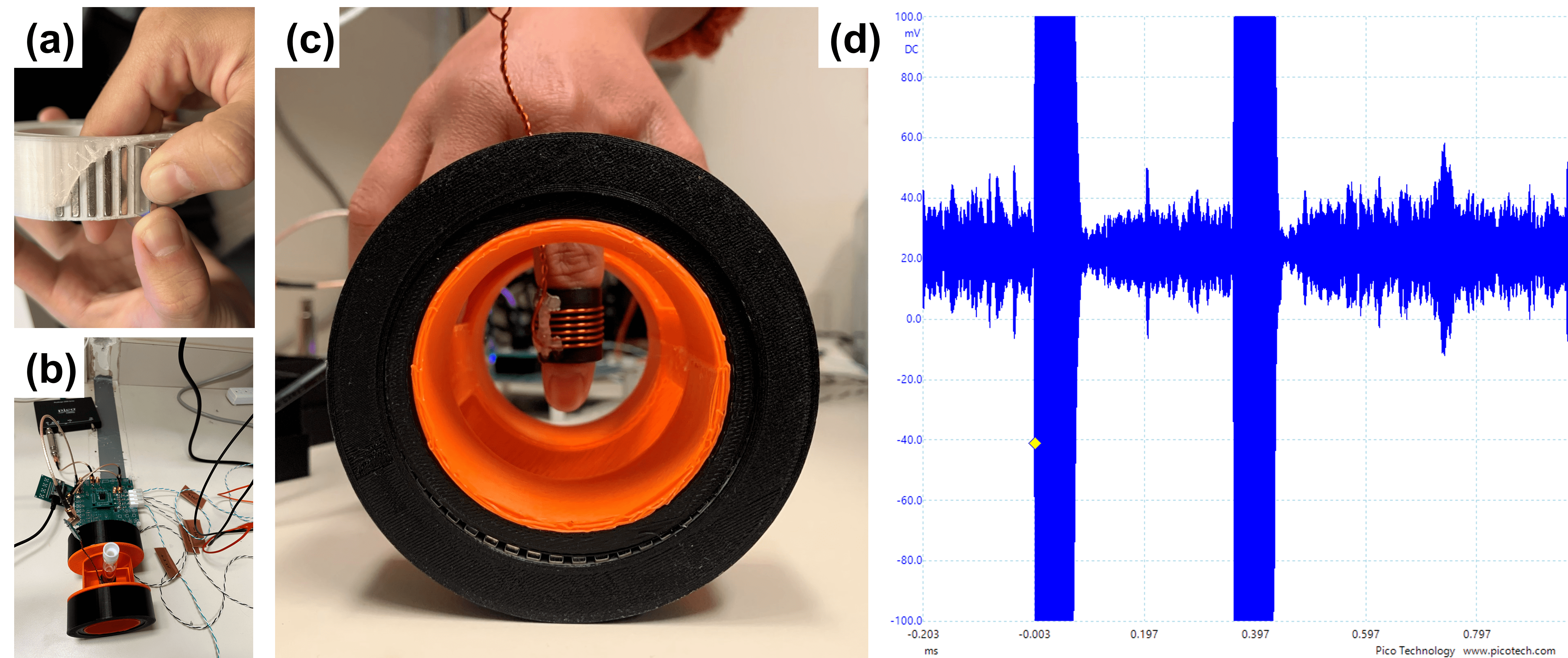
Figure 2 shows the measured field map of the magnet compared to the simulated field maps where the desired field-of-view (FOV) is highlighted in gray. It is observed that the simulated and measured magnetic field align closely, and that homogeneity is greatest within ±10mm of the origin (z=0). A shorter echo time (700 microseconds) was used when obtaining spin echoes to minimize the effect of the inhomogeneities within the magnetic field. Figure 3 shows the averages of fifty RF pulse spin echoes when exciting a 16mm test tube of Gadolinium-doped water. The frequency spectrum in Figure 4 shows a 20kHz bandwidth, matching the simulated field inhomogeneity of 0.5 mT, primarily in the z-direction (see Figure 1). To demonstrate potential for imaging human anatomy, we also present a spin echo acquired from a finger in Figure 5. The reproducible spin echoes validate the scalability of both the permanent magnet topology and the signal chain for the handheld MR magnet.Discussion and Conclusion
This scaled-up, lower-field prototype of the spokes-and-hub magnet verifies the scalability of the spokes-and-hub magnet design. Comparisons of the measured and simulated field maps, along with the generated spin echoes for different imaging volumes, demonstrate the feasibility of this low-field permanent magnet infrastructure for imaging. The previously developed methodology for building the small-scale permanent magnet handheld MR topology, including B0 field modeling in simulation and the signal chain for producing Bloch-optimized dithered pulses, proved to be successful in translating to a prototype that is twice as large and less than half the Larmor frequency as the original. The larger structure of the spokes-and-hub magnet allows for point-of-care imaging for more interesting human anatomy, with the eventual goal of the creation of a system that is more effectively optimized to be capable of clinical applications.Acknowledgements
Funding support from NIH NIBIB R01EB018976, DoD NDSEG Fellowship, and MIT EECS departmentReferences
1. Aubert G, Cylindrical permanent magnet with longitudinal induced field, US5014032A, 1991.
2. Hugon C, D’Amico F, Aubert G, Sakellariou D. Design of arbitrarily homogeneous permanent magnet systems for NMR and MRI: theory and experimental developments of a simple portable magnet. J. Magn. Reson. Imaging, 2010.
3. Ren ZH, Mu WC, Huang SY. Design and Optimization of a Ring-Pair Permanent Magnet Array for Head Imaging in a Low-Field Portable MRI System. IEEE Transactions on Magnetics, Vol. 55, 2019.
4. Huang SY, Ren ZH, Obruchkov S, Gong J, Dykstra R, Yu W. Portable Low-Cost MRI System Based on Permanent Magnets/Magnet Arrays. iMRI, 2019.
5. Kuang I, Arango N, Stockmann J, Adalsteinsson E, White J. Equivalent-Charge-Based Optimization of Spokes-and-Hub Magnets for Hand-Held and Classroom MR Imaging. Proc. Intl. Soc. Mag. Reson. Med. 27., 2019.
6. Kuang I, Arango N, Stockmann J, Adalsteinsson E, White J. Bloch-Optimized Dithered-Ultrasound-Pulse RF for Low-Field Inhomogeneous-Permanent-Magnet MR Imagers. Proc. Intl. Soc. Mag. Reson. Med. 28., 2020.
Figures