1770
Characterization of Concomitant Gradient Fields and their effects on a 46 mT Halbach-Based point-of-care MRI system1C.J. Gorter MRI Center, Leiden University Medical Center, Leiden, Netherlands, 2Circuits and Systems, Delft University of Technology, Delft, Netherlands
Synopsis
Keywords: Low-Field MRI, Artifacts, Concomitant fields
Low field Halbach systems are susceptible to concomitant gradient effects. The associated fields are significantly different from clinical systems and are presented here for the first time. The corresponding equations and associated effects are verified using a spin echo sequence on a 46 mT Halbach system where a gradient strength of 10 mT/m on a phantom with maximum dimension of 200 mm is observed to create distortions. These are most evident in the transverse plane, where the phase encoding gradient causes blurring and overlapping the other transverse gradient lobe results in an additional warping effect.Introduction
Magnetic field gradients have undesired but unavoidable vector-components known as concomitant fields. Their effects have been extensively studied at clinical field strengths1, where distortions occur for large field of views2 and when using sequences, such as spiral, EPI and RARE4-5, which are sensitive to phase errors. At low field (<0.6T), gradient fields for a given field of view become more significant with respect the background field. Therefore, distortions are to be expected for smaller field of views and using sequences such as conventional spin and gradient echo6. For low-field point-of-care (POC) systems, the effects of concomitant fields have not yet been extensively modelled: notably the cylindrical gradient coils designed for a transverse B07 create concomitant fields which are geometrically different than in clinical systems.In this work the concomitant fields associated with a Halbach-array-based system are derived. The effects were simulated and verified by acquiring spin-echo images on a 46mT system.
Methods
Maxwell’s equations require that in a source-free region the magnetic flux density must be curl and divergence free. Consequently, the components of the magnetic flux density can be expressed with the following matrix vector product1$$\begin{bmatrix}B_x\\B_y\\B_z-B_0 \end{bmatrix}=\begin{bmatrix}-\alpha G_z&0&G_x\\0&(\alpha -1)G_z &G_y\\G_x&G_y&G_z\end{bmatrix}\begin{bmatrix}x\\y\\z\end{bmatrix},\quad(1)$$
where B0 is in the $$$z$$$-direction. For a Halbach system $$$x$$$ represents the axial, and $$$y$$$ the vertical, direction. In (1) the $$$\alpha$$$-term is determined by the gradient coil geometry. Conventional systems have $$$\alpha=0.5$$$: in contrast, numerical simulations of our gradient coils reveal that $$$\alpha=0$$$.
The magnitude of the magnetic flux density is required to determine the phase error and deflection from the main concomitant field component. This is evaluated using a Taylor expansion: for Halbach systems this has the following form
$$|\textbf{B}(\textbf{r},\textbf{g})|\approx B_0+\textbf{g} \cdot \textbf{r}+\frac{1}{2B_0}\left[ (G_y^2+ G_x^2)z^2+G_z^2 y^2-2G_yG_z yz \right] + \frac{1}{2B^2_0}[..., \quad (2)$$
where $$$B_0+\textbf{g}\cdot\textbf{r}$$$ are the desired components for imaging, and the remaining terms describe the concomitant fields. The majority of the concomitant field effects are represented by the $$$\frac{1}{2B_0}$$$ terms, i.e. three self-squared and a single cross-term. The effects of these terms for a spin-echo sequence were simulated in Matlab using a phantom of multiple tubes: experimental results were obtained using a corresponding physical realization of doped water-filled tubes. Additional experimental results were obtained from a 1cm thick (transverse) brain slab phantom with dimensions 180x200mm and compartments containing agarose doped with CuSO4, such that relaxation times correspond to brain tissue at 50mT8.
The 46mT system has a maximum gradient strength of 10mT/m, and so to investigate the effects of stronger gradients an additional bipolar pulse, which only creates concomitant phase is added (Fig.1). Fig.1A. shows the pulse sequence used to depict the effect of the self-squared-terms. In Fig.1B. the dephasing and phase gradient lobes are overlapped to add the effect of the cross-term.
Results
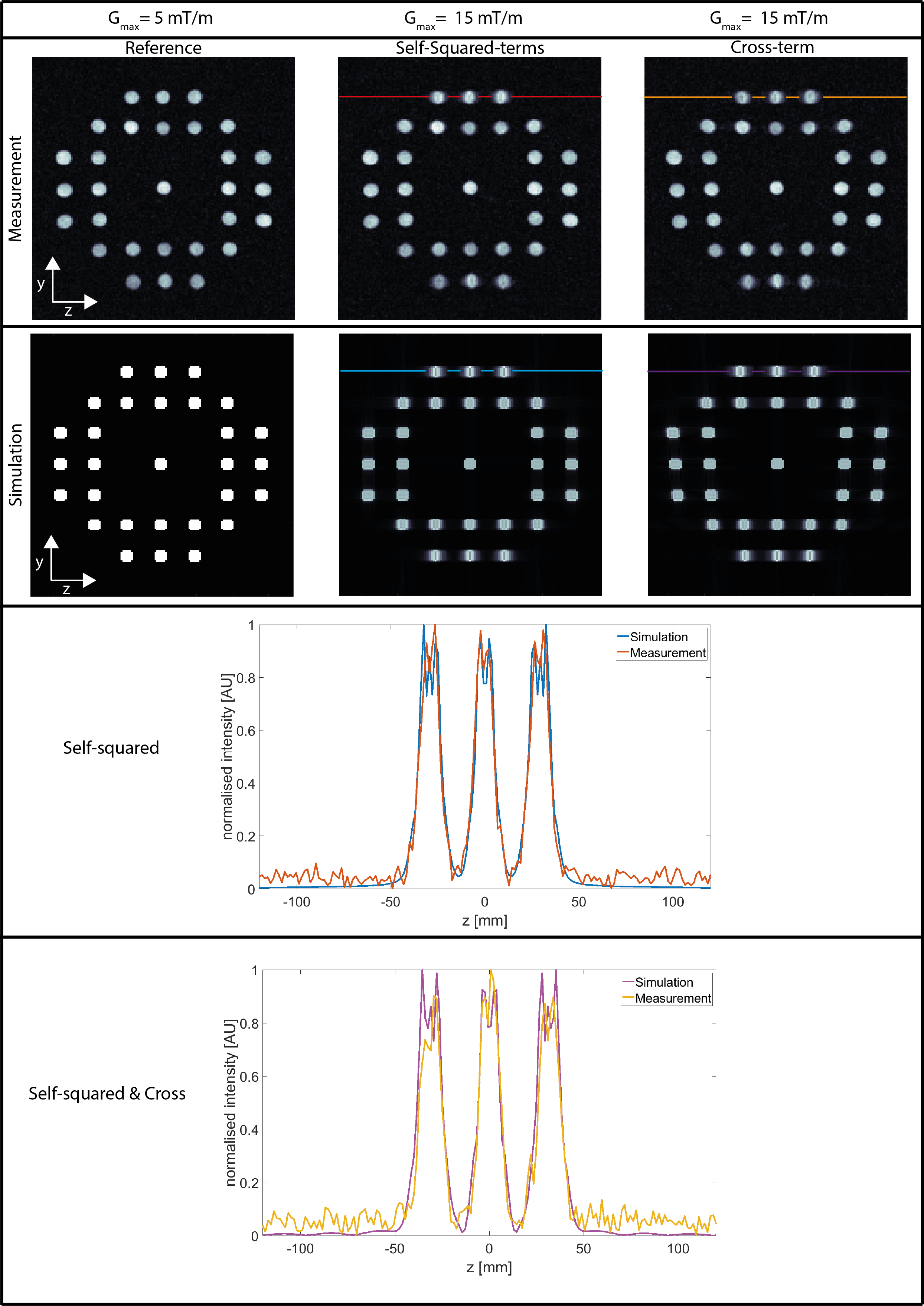
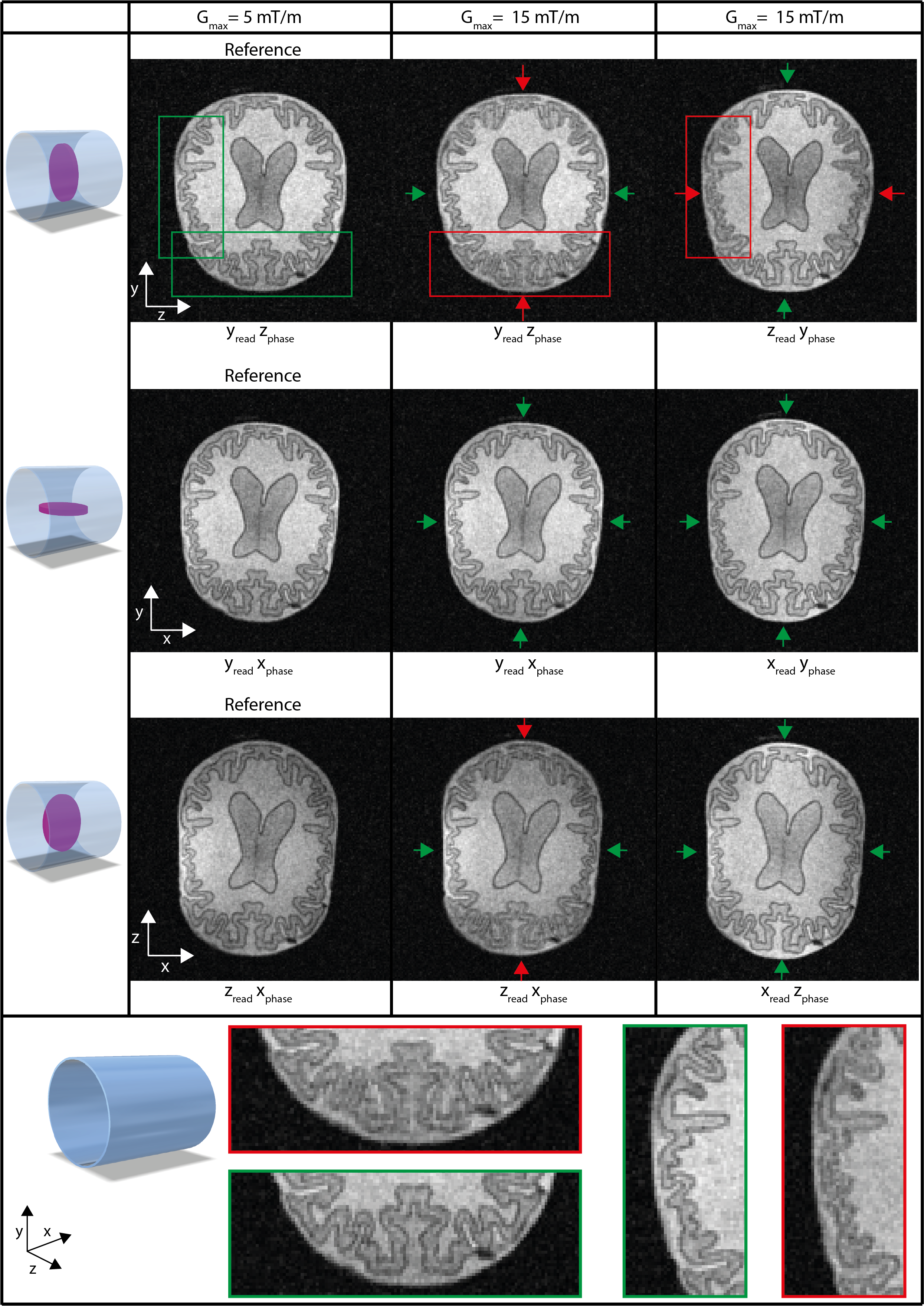
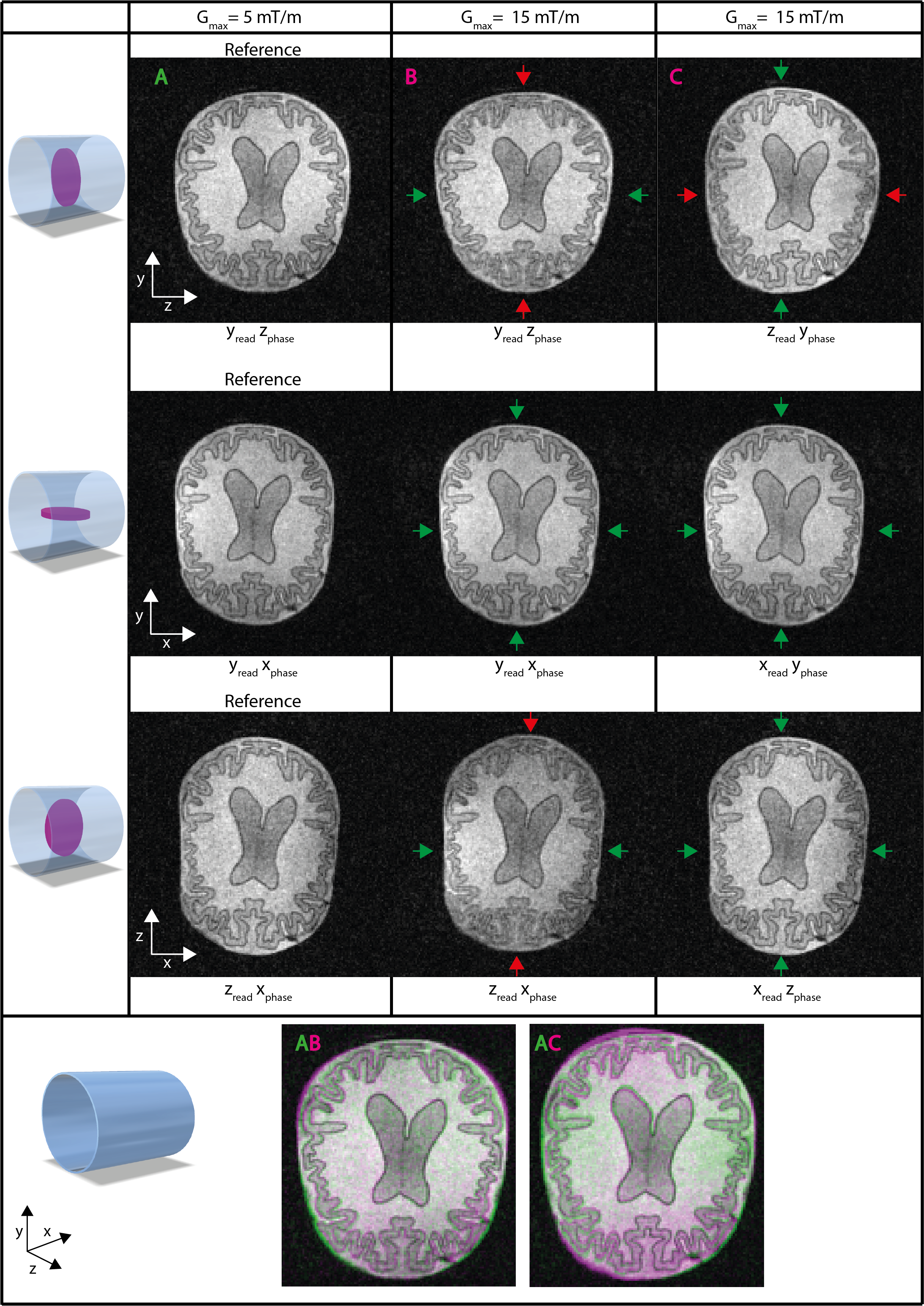
The tube phantom simulations were compared with measurements, the results are shown in Fig.2. Equation (2) shows that when using $$$z$$$ as the phase encoding gradient, blurring is expected to occur for large values of $$$|y|$$$: this is confirmed by the significant blurring visible around the top and bottom tubes. In addition, the cross-term causes an additional warping effect visible in the right column images. A 1D profile of the tubes shows close correspondence between the simulation and measurement in terms of broadening and warping.Fig.3. shows images of the brain phantom oriented in three planes using the different encoding gradients. Each plane is compared to a reference image (left column). The red arrows show where blurring due to concomitant gradients is expected, the green arrows where no blurring should occur. The concomitant fields are expected to be constant in the $$$x$$$-direction, this is visible from the absence of distortions in the $$$xy$$$-plane (second row). Fig.4. shows that overlapping the $$$y$$$- and $$$z$$$-gradient (de)phase-lobes adds a warping effect with respect to the reference image, confirming the single cross-term in equation (2). The other gradients can be overlapped without additional effects.
Fig.5. shows the brain phantom for a maximum phase encoding gradient strength of 5mT/m, and “artificial” strengths of 10 and 15mT/m. The left column shows the effect of the self-squared-terms and the right column the addition of the cross-term. Blurring and warping become visible at 10mT/m as indicated by the red arrows.
Discussion
This work presents first analysis and demonstration of the effects of concomitant gradient fields on the image quality of low-field POC systems. The results obtained at 46mT show that the effects produce blurring for head-sized objects, particularly in the areas close to the surface in the phase-encoding directions. This is contrary to clinical MRI systems where the effects are more pronounced at the extremities in a direction along the magnet bore. An additional difference is that gradients for Halbach systems have only one, rather than two, cross-terms.The concomitant field effects were evident from a gradient strength of 10mT/m upwards for spin-echo sequences. We anticipate that for more practical sequences such as RARE, phase accumulation throughout the echo train will mean that distortions may occur at lower gradient strengths. Further analysis will also allow us to develop different correction strategies, such as applying phase correction before reconstruction, or appropriate variations of quadratic nulling5 to resolve the effects of self-squared terms.
Acknowledgements
This work was supported Simon Stevin Meester PrizeReferences
1. Bernstein MA, King FK, Xiaohong JZ. Concomitant-Field Correction Gradients, in: Handbook of MRI Pulse Sequences, pp:292-304
2. Zhou XJ, Du YP, Bernstein MA, et al. Concomitant Magnetic-Field induced Artifacts in Axial Echo Planar Imaging. MRM. 1998;39:596-605.
3. Bernstein MA, Zhou XJ, Polzin JA, et al. Concomitant Gradient terms in Phase Contrast MR: Analysis and Correction. MRM. 1998;39:300-308
4. King KF, Ganin A, Zhou XJ, Bernstein MA. Concomitant Gradient Field Effects in Spiral Scans. MRM 1999;41:103-112
5. Zhou XJ, Tan SG, Bernstein MA. Artifacts Induced by Concomitant Magnetic Field in Fast Spin-Echo Imaging. MRM 1998;40:582-591.
6. Volegov PL, Mosher JC, Espy MA, Kraus RH. On concomitant gradients in low-field MRI. JMR 2005;175:103-113.
7. de Vos B, Parsa J, Abdulrazaq Z, et al. Design, Characterisation and Performance of an Improved Portable and Sustainable Low-Field MRI System. Front in Phys 2021
8. O’Reilly T, Webb AG, In vivo T1 and T2 relaxation time maps of brain tissue, skeletal muscle, and lipid measured in healthy volunteers at 50 mT, MRM 2021;87:884-895.
Figures
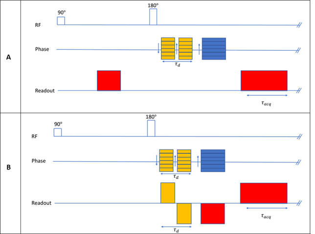
(1) Sequence diagrams of two spin echo sequences used to separately study the effects of the self-squared- and cross-term in Equation (2). Red represents frequency encoding lobes, blue the phase encoding and yellow the additional bipolar pulses. (A) is used to demonstrate the effect of the self-squared-terms while (B) is used to demonstrate the effects of overlapping the read-dephase and phase encoding gradient lobes.
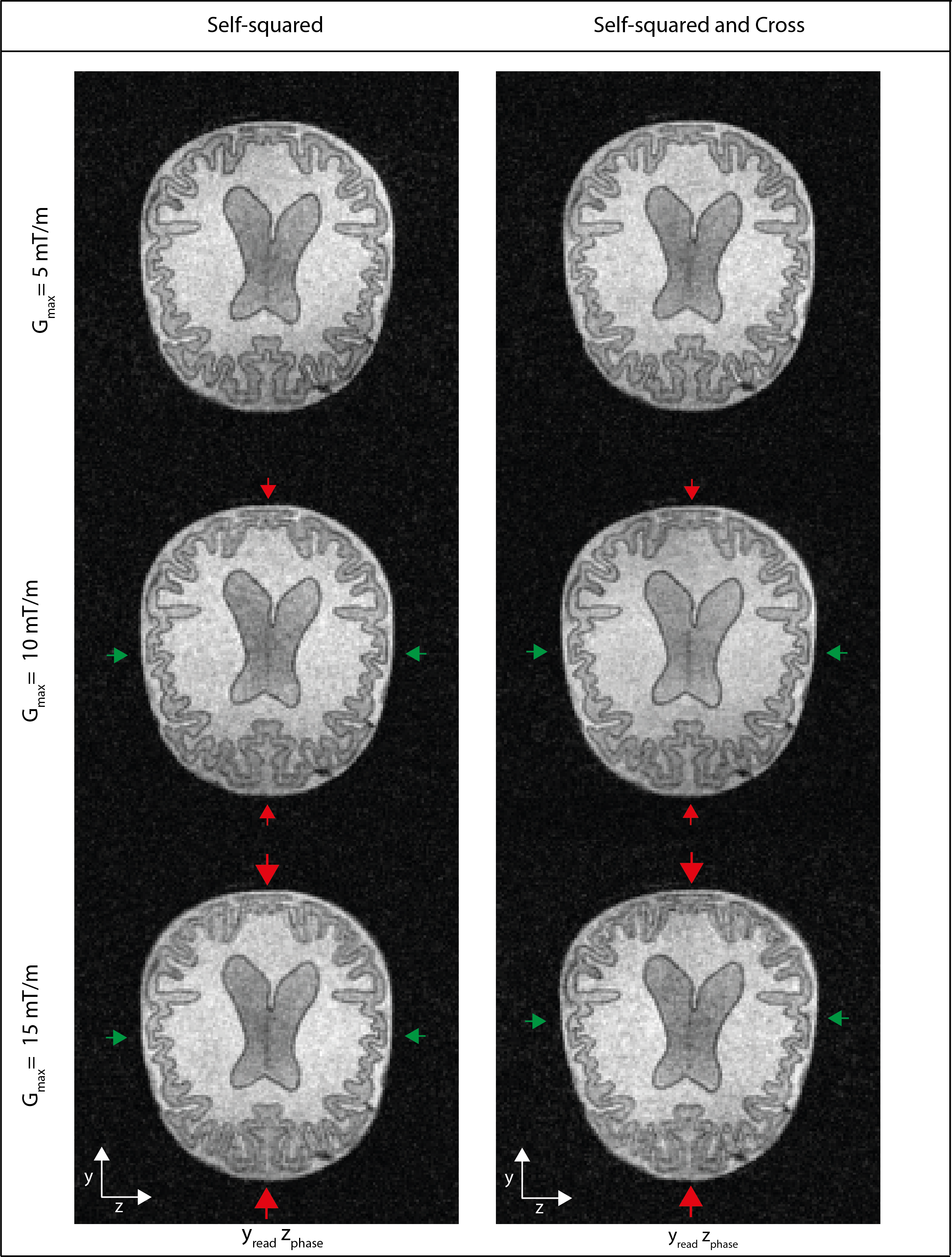
(5) Phantom images obtained with the 2D spin echo sequence shown in Figure 1A (left column) and Figure 1B (right column). The transverse orientation is shown, with the encoding yz (readout, phase), for increasing gradient strengths (top to bottom). Blurring in the phase encoding direction starts to become visible at 10 mT/m as well as slight warping effect in the right column (cross-term). red arrows depict where blurring and/or warping is expected, green where no distortions should occur. Acq param: FOV: 240x240, Data Matrix: 160x160, TR/TE=300/50, NA=12.