1766
Feasibility of integrating a wearable accelerometer in very low-field MRI to detect motion
Keerthi Sravan Ravi1,2, Kunal Aggarwal3, John Thomas Vaughan Jr.2, Yun Soung Kim4, and Sairam Geethanath5
1Biomedical Engineering, Columbia University, New York, NY, United States, 2Columbia Magnetic Resonance Research Center, Columbia University, New York, NY, United States, 3Accessible MR Lab, BMEII, Diagnostic, molecular and interventional radiology, Icahn School of Medicine at Mt. Sinai, New York City, NY, United States, 4Biomedical Engineering and Imaging Institute, Dept. of Diagnostic, Molecular and Interventional Radiology,, Mt.Sinai, New York, NY, United States, 5Accessible MR Laboratory, Biomedical Engineering and Imaging Institute, Dept. of Diagnostic, Molecular and Interventional Radiology,, Mt. Sinai, New York, NY, United States
1Biomedical Engineering, Columbia University, New York, NY, United States, 2Columbia Magnetic Resonance Research Center, Columbia University, New York, NY, United States, 3Accessible MR Lab, BMEII, Diagnostic, molecular and interventional radiology, Icahn School of Medicine at Mt. Sinai, New York City, NY, United States, 4Biomedical Engineering and Imaging Institute, Dept. of Diagnostic, Molecular and Interventional Radiology,, Mt.Sinai, New York, NY, United States, 5Accessible MR Laboratory, Biomedical Engineering and Imaging Institute, Dept. of Diagnostic, Molecular and Interventional Radiology,, Mt. Sinai, New York, NY, United States
Synopsis
Keywords: Low-Field MRI, Low-Field MRI
These artifacts degrade image quality, often causing misdiagnosis. A 6-axis motion tracking sensor (ICM-20649, TDK-InvenSense) with a full-scale range of +-4000 degrees per second for the gyroscope and +-30g for the accelerometer was integrated with a 50mT scanner. The sensor’s readings can successfully be processed to detect motion. However, it resulted in zipper artifacts and degraded image quality in a phantom experiment. Still, the sensor’s placement on the forehead or the temples or the chin might not significantly impact brain data when coupled with slab-wise shimming.Introduction
MRI is a lifesaving technology capable of producing excellent soft tissue contrast. However, it is time-consuming, and this primarily results in motion artifacts as a consequence. These artifacts degrade image quality, often causing misdiagnosis1. Mitigation approaches span across acquisition, reconstruction, and post-processing steps of the MRI pipeline2. In the case of severe motion artifacts, data are discarded and rescans are required, resulting in wasted resources such as hardware time and the necessity of repeat appointments. Andre et al. reported a base-case cost estimate yielded a potential cost of $592 per hour in lost revenue due to motion artifacts, at the institution they reviewed3. In low field and very low field (VLF) strengths, the effects of motion artifacts are exacerbated because of inherently lower SNR. In this work, we investigate the feasibility of employing a wearable motion tracking sensor in a VLF scanner to detect subject motion.Methods
A 6-axis motion tracking sensor (ICM-20649, TDK-InvenSense) with a full-scale range of +-4000 degrees per second for the gyroscope and +-30g for the accelerometer was utilized in this work. The sensor could pair with an Android device via Bluetooth to facilitate real-time capture of its output. Only the accelerometer’s readings were considered in this work. The sensor recorded readings from the accelerometer in all 3 Cartesian coordinate planes, individually. Three experiments were performed. The first was to perform dimensionality reduction of the accelerometer’s readings and to explore the feasibility of utilizing this signal to detect motion. Figure 1 illustrates the experimental setup: the sensor was attached to a toy car model for easier handling. This rig was manually rotated about each axis in separate trials, and the sensor’s readings were recorded. The L1 norm of the accelerometer’s readings in the x, y, and z planes was obtained as a method of dimensionality reduction. The second experiment was to investigate the feasibility of utilizing the sensor inside the bore of a very low field 50 mT, Multiwave Technologies SA, France)scanner. Data were acquired with and without the sensor attached to the phantom. The median local SNR4 was computed to quantitatively measure image quality. The third experiment simulated subject motion inside the scanner, during an acquisition. For both experiments, a 3D Turbo Spin Echo pulse sequence was executed to image a Pro-MRI phantom (Medical Device Depot Inc.). In experiment three, we rotated the phantom at the beginning of the scan. We recorded the accelerometer readings during the scan to detect the time and extent of motion. The L1 norms of the accelerometer’s readings were obtained and graphed to observe motion in experiment 3, similar to experiment 1.Results and discussion
Experiment 1’s setup is illustrated in Figure 1, while Figure 2 plots the accelerometer’s readings from the 3 trials. The L1 norm indicates the presence of motion in approximately the last 50 seconds of each trial. Figure 3 illustrates the setup for experiment 2 and also presents representative slices from the acquired data. The presence of zipper artifacts and signal loss is clearly observed when the sensor is present inside the bore during the acquisition. The median local SNR of the acquired data, with and without the sensor, are 14.401 and 17.58 (a.u.), respectively. The discrepancy in the higher median value for the poorer quality acquisition can be attributed to the higher intensity values in the zipper artifact skewing the local SNR distribution. The median local SNR values on a crop of the acquired data, such that only the phantom was considered in the computation, were 26.32 and 23.95, as expected. The signal loss was not observed in 5 out of 25 slices. Figure 4 shows the motion-occurrence detection capability of the sensor (vertical arrow). The effect of motion and sensor-induced distortion is seen in Figure 4c. The accelerometer’s signals can be leveraged by a deep learning network to classify the severity of the motion artifact if detected5. Potentially, this near real-time feedback from the sensor can enable informed image reconstruction methods such as discarding corrupted k-space lines.Conclusion
We investigated the feasibility of utilizing a wearable motion tracking sensor to detect subject motion during acquisition in a VLF scanner. The sensor’s readings can successfully be processed to detect motion. However, it resulted in zipper artifacts and degraded image quality in a phantom experiment, with local SNR values of 26.32 and 23.95, with and without the sensor, respectively. In the case of in vivo experiments, we expect the metal-induced inhomogeneity to impact shimming. Still, the sensor’s placement on the forehead or the temples might not significantly impact brain data when coupled with slab-wise shimming. Future work involves a detailed study of the RF heating due to the sensor’s integration.Acknowledgements
The authors acknowledge Dr. Pavan Poojar for his input on the low-field scanning and support from the Faculty Idea Innovation Prize, 2022, from the office of faculty development, Icahn School of Medicine at Mt. SinaiReferences
- Krupa, K. and Bekiesińska-Figatowska, M., 2015. Artifacts in magnetic resonance imaging. Polish journal of radiology, 80, p.93.
- Smith, T.B., 2010. MRI artifacts and correction strategies. Imaging in Medicine, 2(4), p.445.
- Andre, J.B., Bresnahan, B.W., Mossa-Basha, M., Hoff, M.N., Smith, C.P., Anzai, Y. and Cohen, W.A., 2015. Toward quantifying the prevalence, severity, and cost associated with patient motion during clinical MR examinations. Journal of the American College of Radiology, 12(7), pp.689-695.
- Golshan, H.M., Hasanzadeh, R.P. and Yousefzadeh, S.C., 2013. An MRI denoising method using image data redundancy and local SNR estimation. Magnetic resonance imaging, 31(7), pp.1206-1217.
- Jimeno, M.M., Ravi, K.S., Jin, Z., Oyekunle, D., Ogbole, G. and Geethanath, S., 2022. ArtifactID: Identifying artifacts in low-field MRI of the brain using deep learning. Magnetic resonance imaging, 89, pp.42-48.
Figures
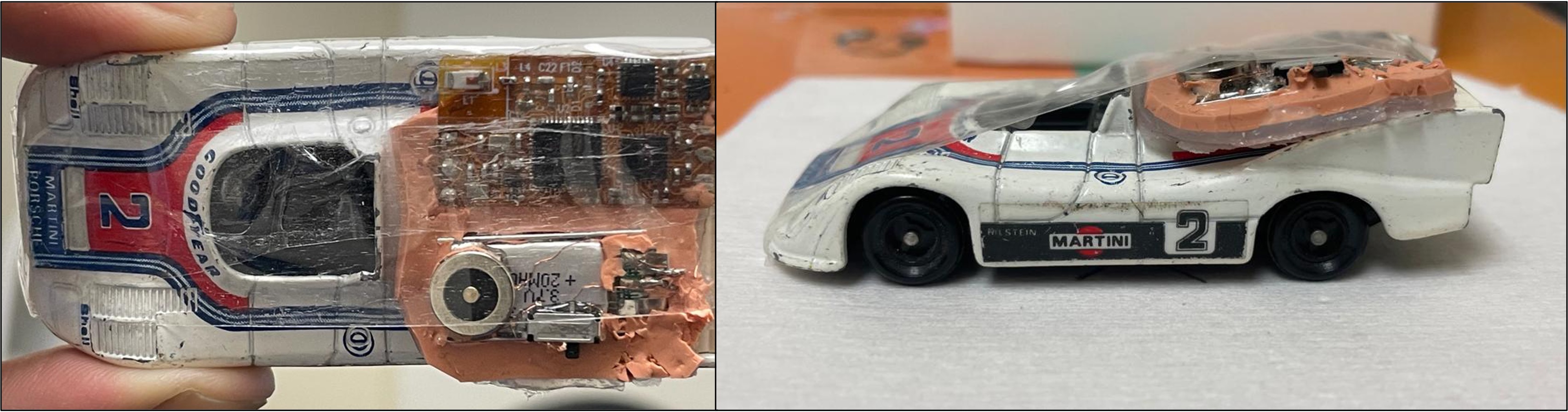
Figure 1: Experiment 1 setup.
The motion tracking sensor was attached to a toy car model for easier handling.
This rig was rotated across each individual axis in 3 separate trials. The L1
norm of the accelerometer’s readings were plotted (Figure 2).
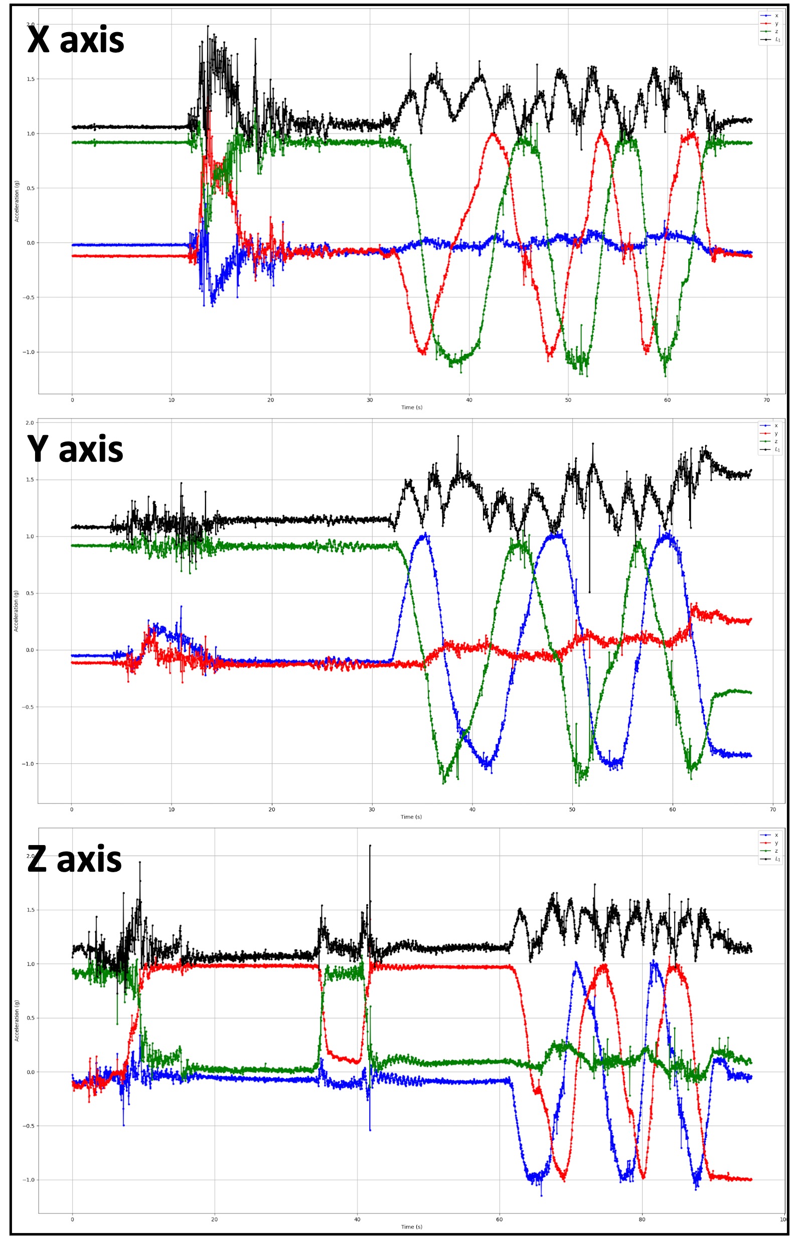
Figure 2: Dimensionality reduction to detect
motion. Plot of L1 norm (black) of the
accelerometer’s readings in the x, y, and z Cartesian planes, as a function of
time. Occurrence of motion can be detected by observing the L1 norm values.
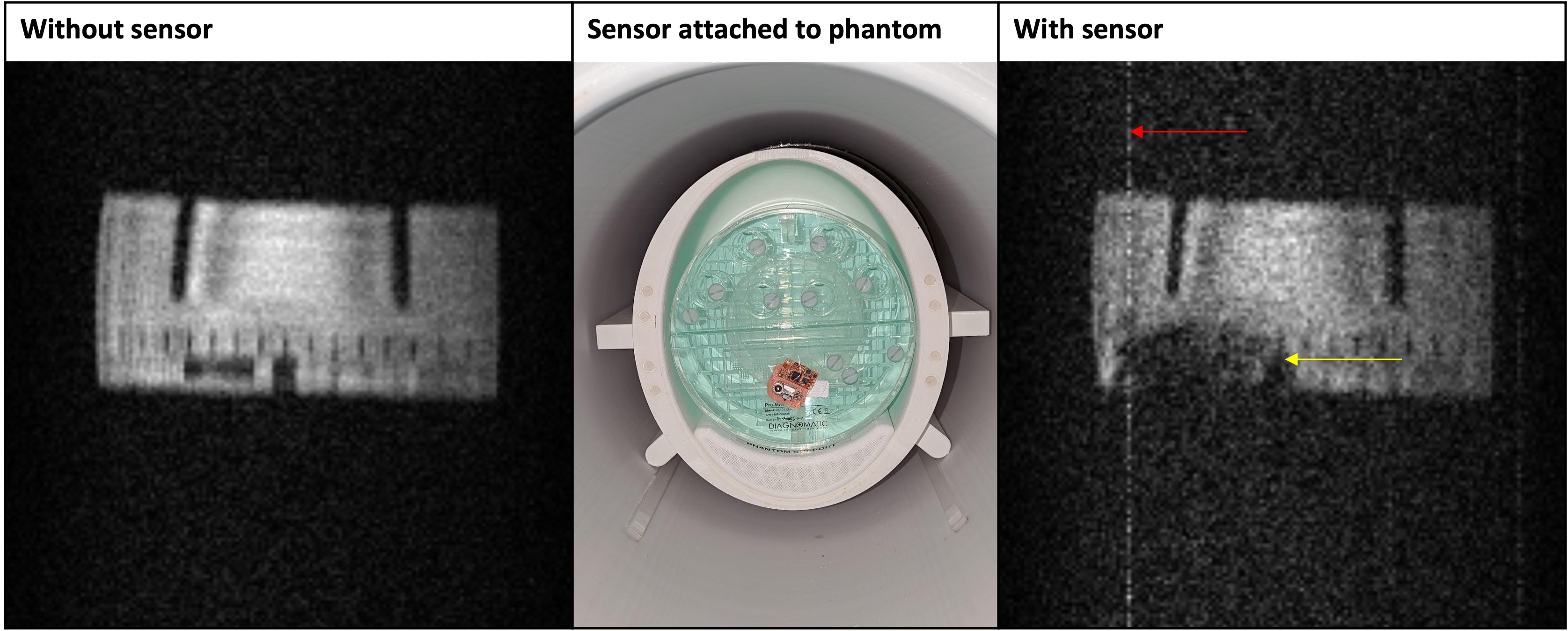
Figure 3: Experiment 2 setup and image
reconstructions. Representative slices of
reconstructed images from experiment 2. Attaching the sensor to the Pro-MRI
phantom induced zipper artifacts (red arrow) and caused signal loss (yellow
arrow) resulting in degraded image quality.
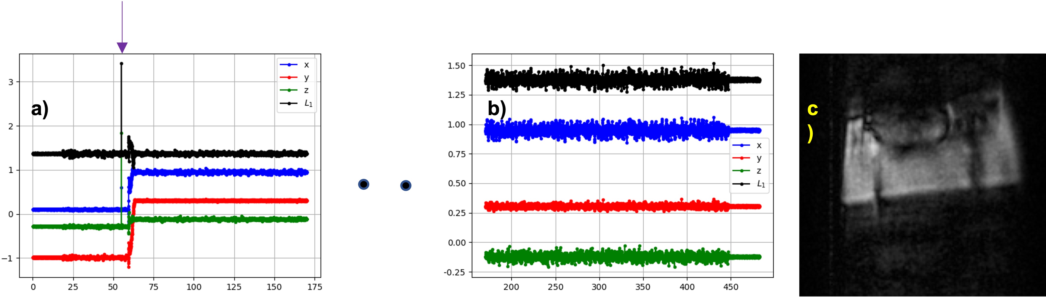
Figure 4: Experiment 3
– detecting time of motion. a)
The arrow shows the precise time instant of motion occurrence b)
a
snapshot of the accelerometer
reading toward the end of the experiment; c) motion and sensor-induced
distortion corrupted image
DOI: https://doi.org/10.58530/2023/1766