1603
Outer Volume Saturation using Adiabatic Inversion Pulses in an Inhomogeneous Transmit Field1Promaxo, Oakland, CA, United States, 2Yale School of Engineering & Applied Science, Yale, New Haven, CT, United States
Synopsis
Keywords: RF Pulse Design & Fields, Low-Field MRI
A method for saturating the outer volume in a single sided low field MRI scanner has been developed. By saturating the outer volume using this method, magnetization from regions where the gradient fields are highly nonlinear may be removed from the image, resulting in less image artifacts.Introduction
Promaxo has developed a low field single sided MRI scanner for pelvic scanning. This scanner projects magnetic fields from its surface, making the system open and accessible. This is done by placing the gradient and transmit coils on the surface of the magnet. This scanner geometry produces highly nonlinear gradient fields, which can introduce artifacts into the image. This nonlinearity becomes worse as one moves further from the center of the field of view (FOV) which makes saturating this outer volume desirable. In typical applications, outer volumes are saturated by selectively saturating the edges with selective excitations using the gradient fields1. The Promaxo scanner has a permanent gradient, so regions in space cannot be arbitrarily excited. Therefore, an alternative saturation technique that can be applied to a single sided system is needed. To that end, a new form of outer volume saturation (OVS) that makes use of the spatial variation in the transmit field has been developed.Generally, transmit RF fields used in MRI are designed to be as homogeneous as possible. However, the single sided design of the Promaxo scanner makes it difficult to generate a homogeneous transmit field. Instead, the field tends to be stronger in the middle of the FOV and taper off at the edges. However, this spatial variation in field strength can help selectively saturate regions where the fields are weak with the use of chirped pulses2. If the adiabatic pulse is strong enough, the magnetization will be inverted by the end of the pulse. Weaker field strengths will result in the pulse either rotating the magnetization to the transverse plane or leaving it in the longitudinal axis3. In this study, we develop a pulse sequence that saturates the signal in these regions using the inhomogeneous transmit field produced by the Promaxo scanner’s surface transmit coil.
Materials and Methods
All 3D images were collected with a RARE style pulse sequence (figure 2). Two OVS pulses were used during this experiment, with a constant pulse duration of 1.5 ms and increasing pulse power. Scans were done on an American College of Radiology (ACR) extremity phantom surrounded by bags of water doped with contrast agent. A Bloch simulation of the outer volume saturation was also performedResults
Figures 1 and 3 shows how the nonlinear response to the longitudinal magnetization to the power of the OVS pulses. As the power of the pulses increases, simulations predict that the magnetization is first excited and then inverted when the adiabatic pulses have sufficient power. Unlike conventional pulses, the flip angle of adiabatic pulses will plateau to 180 degrees with enough power. A plot of the bulk signal (figure 4) collected using the pulse sequence in figure 2 matches the behavior predicted by the Bloch simulation. Spatial variations in the transmit power can be combined with adiabatic inversion pulses to saturate different parts of space. In the middle of the field of view, the magnetization will be at the end of figure 4, where signal has recovered. But at the edges, where the field is weak, the magnetization will be somewhere in the middle of figure 4.This effect can be seen in figure 5, where spatial variation in the transmit field allow for outer volume saturation. At low powers, around 0 to 10 percent of the maximum pulse power, the entire volume is preserved because the flip angle is low in the entire volume. As the power increases, the flip angle gets higher, getting close to total saturation at 25% maximum power. At a power of 30%, the middle of the field of view returns first with the rest of the volume coming in later. The horizontal edges come in first, because that is where the transmitted field is stronger, and the bottom follows afterwards. Once the power of the OVS pulse reaches 95%, the entire volume returns.
Conclusion
The ability to saturate the outer volume with just a series of adiabatic chirp pulses was shown to be feasible. By increasing the number of pulses, more delineation between regions of differing powers can be achieved. Future studies would look into using more pulses and possibly a specially designed transmit coil to achieve more saturation at the edges of the FOV while retaining signal the middle.Acknowledgements
No acknowledgement found.References
1. Smith, T. B. & Nayak, K. S. Reduced Field of View MRI with Rapid , B 1 -Robust Outer Volume Suppression. 1323, 1316–1323 (2012).
2. O’Dell, L. A. The WURST kind of pulses in solid-state NMR. Solid State Nucl. Magn. Reson. 55–56, 28–41 (2013).
3. Casabianca, L. B., Mohr, D., Mandal, S., Song, Y. Q. & Frydman, L. Chirped CPMG for well-logging NMR applications. J. Magn. Reson. 242, 197–202 (2014).
Figures
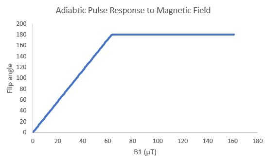
Figure 1: Flip angle of an adiabatic pulse as a function of transmit pulse power. As the power of the pulse increases, the flip angle increases linearly until the flip angle reaches a threshold. Once there, the flip angle stays at 180 degrees.
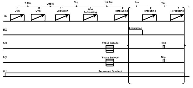
Figure 2: Pulse sequence diagram of the sequence used to collect the images in this abstract. Two OVS pulses are applied before the excitation begins the imaging part of the pulse sequence.
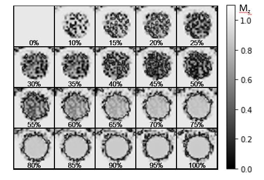
Figure 3: Results from a Bloch simulation of the outer volume saturation. In this example, the phantom is a circular object in the middle of the field of view. At no power, there is no saturation but as the power increases, the center of the field of view becomes dark as the longitudinal magnetization becomes saturated. The magnetization returns as the power of the saturation increases.
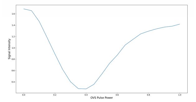
Figure 4: Example of the how the bulk signal changes as the power of the OVS pulses increases. The signal does not reach its original value because of relaxation.
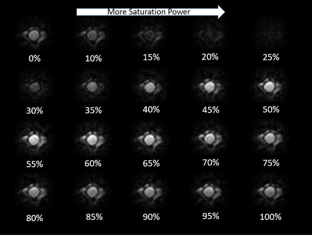
Figure 5: Images of the ACR phantom surrounded by bags of contrast agent doped water at differing OVS pulse powers. At lower powers, neither the center nor the edge is saturated. As the power increases, the middle begins to be saturated more than the edge, until everything is saturated. As the power is increased further, the middle of the field of view returns, followed by the edge.