1589
Optimized Extremity Coil System for Gradient-Free Low-Field MRI using the Bloch-Siegert Shift for RF Spatial Encoding1Biomedical Engineering, Vanderbilt University, Nashville, TN, United States
Synopsis
Keywords: Low-Field MRI, Low-Field MRI
Traditional B0 gradients have several drawbacks including high acoustic noise, PNS, bulkiness, and high cost. To address this, we present a coil system for Bloch-Siegert (BS) RF encoding comprising an optimized square root solenoid with a bucking coil for high efficiency encoding and a nested uniform saddle coil for the imaging Tx/Rx coil at 47.5mT (2MHz), a field strength that is especially attractive due to its low SAR and accessibility. The coil designed for in-vivo imaging was evaluated in simulation including SAR measurements and experimentally on a resolution phantom using a 3D BS phase-encoded imaging and optimized ‘U’ shaped pulses.Introduction
Conventional B0 gradients are loud, compromising patient comfort, and are expensive1. As an alternative to B0 gradients, RF gradient encoding has the potential to bring about low-cost, compact, and silent MR imaging. Here we demonstrate the use of the Bloch-Siegert shift2 due to its ability to produce linear phase/frequency shifts in the transverse plane without modulating the magnitude of the magnetization, at low-field using an optimized coil system for extremity(wrist) in-vivo imaging as well as SAR calculations as pulses used for BS encoding are SAR intensive.Methods
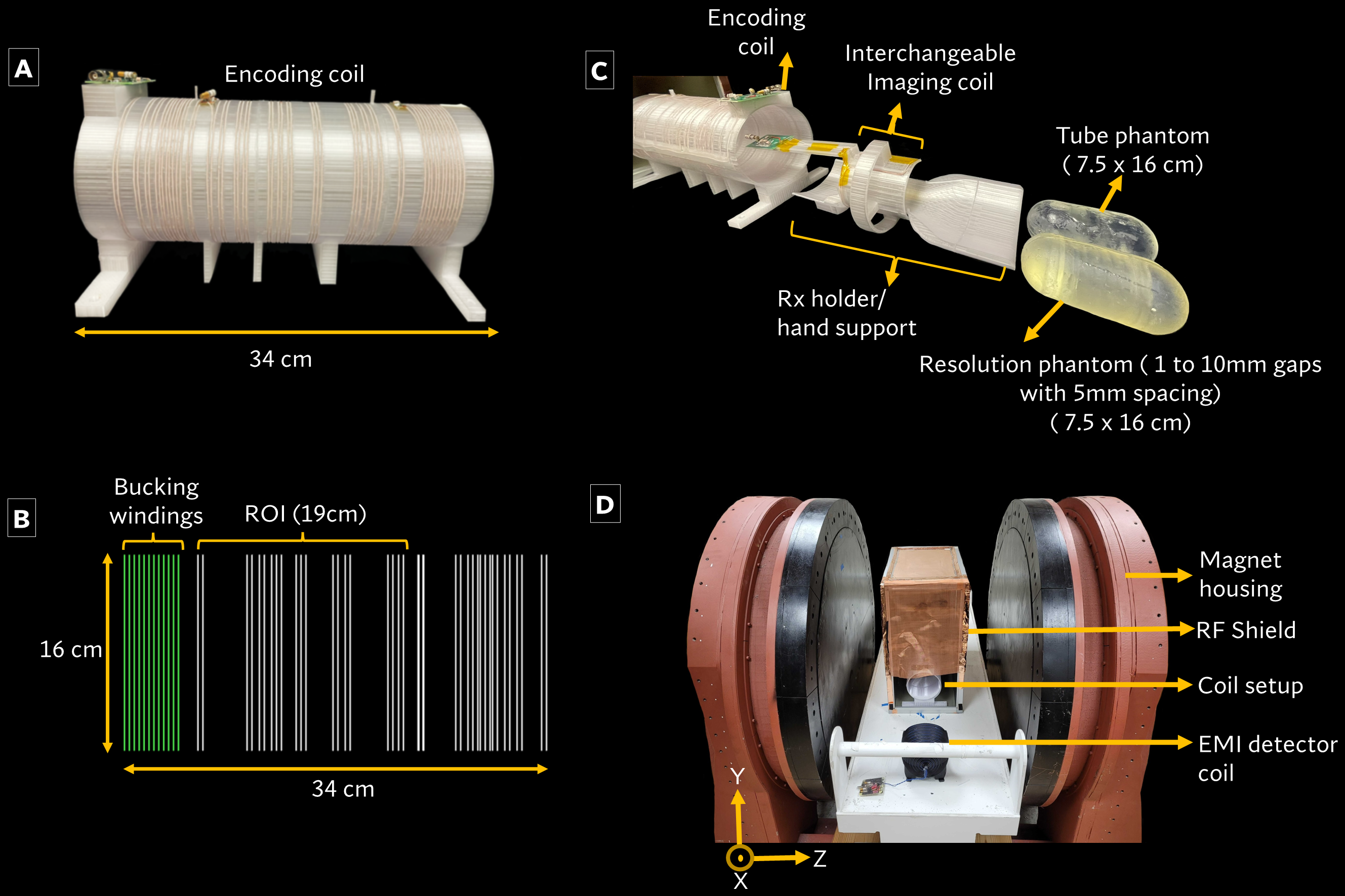
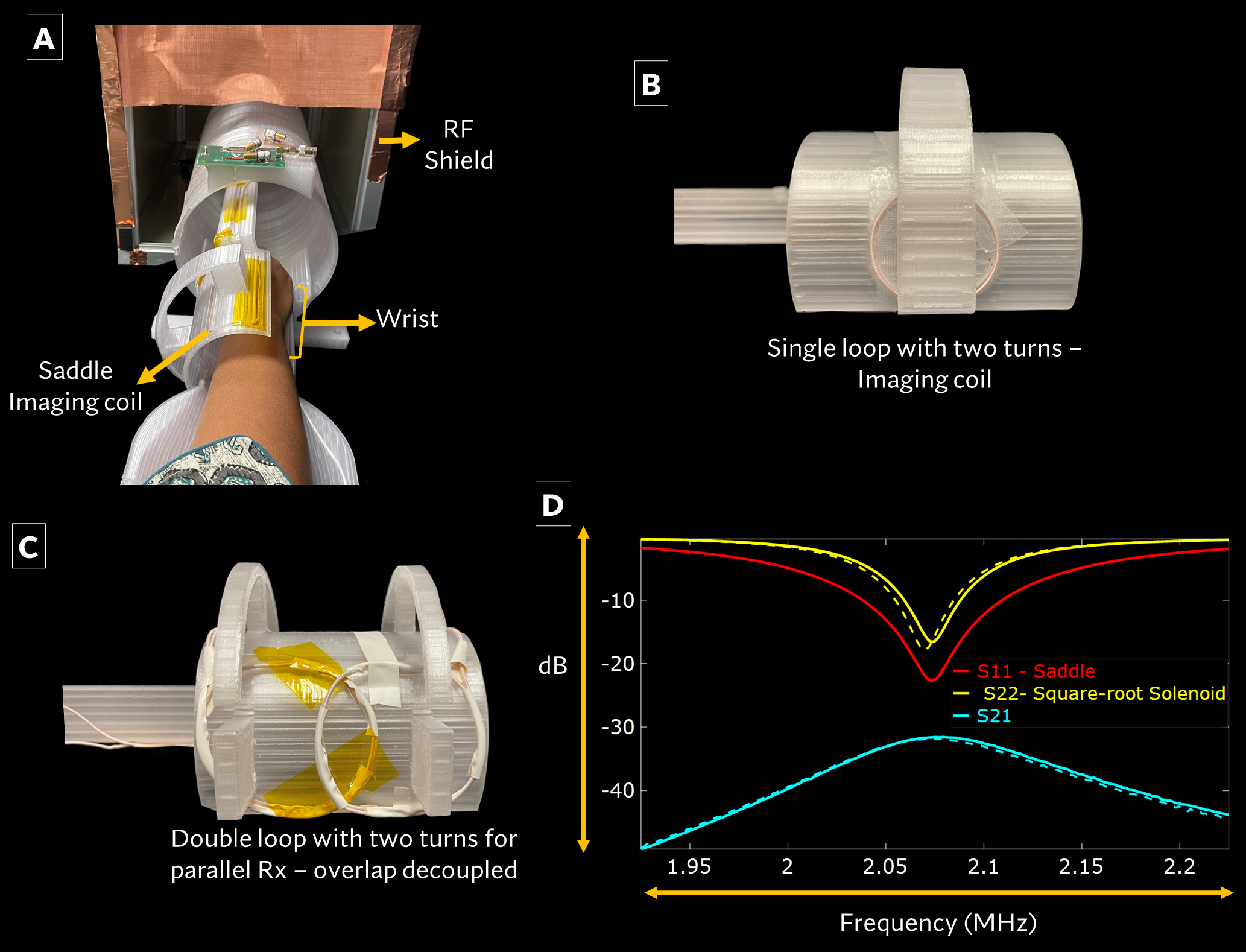
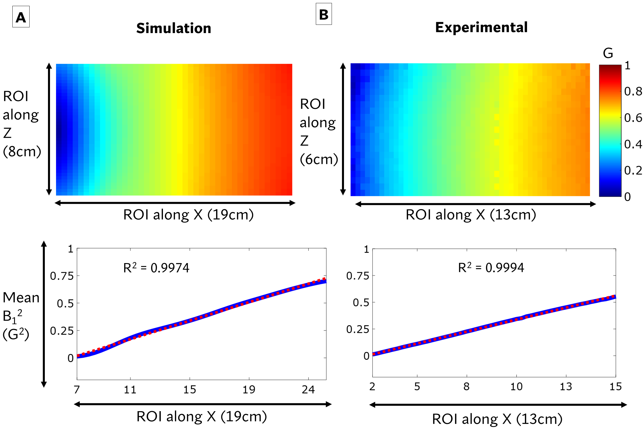
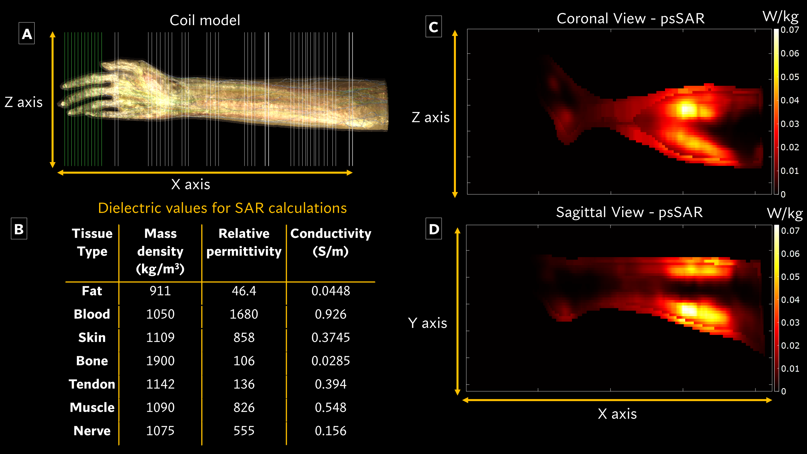
The encoding coil optimization is done using a method like Ref3 which was modified to produce a target field of a square-root field. While this can provide a linear field, it is also essential to be as close to 0 as possible on one end of the coil since only the slope of the field matters and a non-zero intercept on one end represents wasted power. To achieve this, 12 bucking windings were then manually added to the optimized coil design to cancel the fringe $$$B_1^+$$$-field at the low $$$B_1^+$$$-field end. The coil (d=16cm, L=30cm, Total number of windings=52) has ROI of 19cm for the square root field, constructed using Litz wire with two distributed capacitors. The encoding coil and the winding pattern are shown in Figure 1A-B. The measured values of the coil were: L=164uH and Q=60. Due to arcing considerations in in-vivo imaging, a minimum gap of 1mm was used between windings. These bucking windings also reduced the overall inductance of the coil since they are in an opposing series configuration(without bucking L=250uH). A uniform saddle coil was constructed for imaging experiments. Figure 1C-F show the exploded view of the coils and the overall setup for wrist imaging including the phantoms used for validation. Additionally, interchangeable imaging coils (Saddle, loop, and double loop for parallel Rx) can be attached to the imaging coil holder as shown in Figure 2A-C along with the wrist placement in the saddle coil. Figure 2D shows the decoupling between the saddle imaging and encoding coil with and without loading. Since the frequency and phase shifts applied to an object by BS encoding are proportional to $$$B_1^2$$$, Figure 3A shows the $$$B_1^+$$$map acquired through simulations and the average $$$B_1^2$$$profiles.The FDA limits specific absorption rate (SAR) for extremity imaging with a local transmit coil to 20W/kg averaged over 6 mins4. We performed SAR calculations for the wrist using the optimized encoding coil in the magneto-quasistatic simulator in Sim4life (Medtech, Zurich, Switzerland). The Yoon-sun hand model shown in Figure 4A was used with dielectric properties given in Figure 4B. Figures 4C-D show the peak-spatial SAR (psSAR) for 1g of tissue for in the sagittal and coronal planes respectively in the center slices of the hand model. Given our calculations are in continuous-wave mode, we can calculate the SAR for a pulse sequence:
$$SAR = \frac{SAR_{B1} \times \tau }{TR} =SAR_{B1} \times D$$
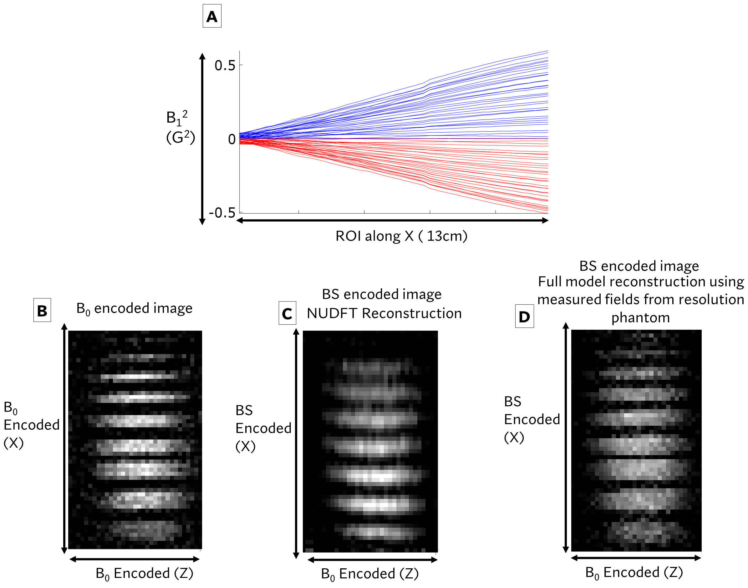
Where $$$\tau$$$ is the length of the BS pulse and D is the Duty-cycle of the pulse. We used a maximum pulse length of 16ms with a minimum TR of 350ms. Two 8ms optimized BS phase-encoding pulses5 with BS frequency-offset=10KHz and Kbs=43 each were used to apply phase encoding. A 3D GRE sequence (Sequence parameters: TE=27.3ms, TR=439ms, NPE=67, NFE=128, Naverages=10) reported previously6 was used with a phase drift navigator on the 47.5 mT scanner (Sigwa, Boston NMR, Boston, MA). The RF coils were placed in a shielded box and remaining EMI was removed using EDITER7. To map the $$$B_1^+$$$field of the encoding coil and to produce the encoding fields using the Bloch Siegert technique8, a rounded cylinder phantom (16cm (L) x 7.5(D)) filled with Mineral oil was used. The$$$B_1^+$$$maps that were experimentally obtained are shown in Figure 2B. Additionally, to validate phase encoding, a resolution phantom (Figure 1C) that was also filled with mineral oil was imaged. To verify RF phase encoding capabilities, the BS pulse amplitude was varied for across 33 amplitudes and two frequency polarities (total encodes=66). The transceiver saddle coil was used with an active TR switch9. The optimized coil was used for encoding. B0 gradients were used for frequency encoding along the Z-direction(kx). Image reconstruction was done using the method described previously6. The encoding fields used are shown in Figure 5A. The B0 encoded image, a NUFFT and the full-model reconstruction of the resolution phantom are shown in Figure 5B-D.
Results
The coil simulation and experimental B12 linear fit had R2 = 0.9974 and 0.9994 with both y-intercepts at 0. The measured decoupling between the coils was ~32dB. The shift between unloaded and loaded conditions was minimal(<3KHz). For the peak B1 of 0.55G and duty-cycle of 0.0457, the simulation yielded a Volume-average SAR= 2.01milliWatts/kg, psSAR averaged over 1g of tissue= 15.1milliWatts/kg and psSAR averaged over 10g of tissue= 7.2milliWatts/kg. All these values are well below the FDA limitations.Discussion and conclusion
In this work we show an optimized coil setup that can do wrist in-vivo BS spatial encoding in one dimension. EMI and B0 shim challenges will be addressed to achieve in-vivo imaging in the future. We also plan to image with the parallel Rx for higher SNR.Acknowledgements
This work was supported by NIH grant R01 EB030414.References
[1] Wald LL, McDaniel PC, Witzel T, Stockmann JP, Cooley CZ. Low-cost and portable MRI. J Magn Reson Imaging. 2020;52(3):686-696. doi:10.1002/jmri.26942
[2] F Bloch and A Siegert. Magnetic resonance for nonrotating fields. Phys Rev, 57:522–527, 1940.
[3] Shen S, Xu Z, Koonjoo N, Rosen MS. Optimization of a Close-Fitting Volume RF Coil for Brain Imaging at 6.5 mT Using Linear Programming. IEEE Trans Biomed Eng. 2021;68(4):1106-1114. doi:10.1109/TBME.2020.3002077
[4] MRI (Magnetic Resonance Imaging) | FDA. Accessed Oct 31st 2022
[5] Martin, JB, Srinivas, SA, Vaughn, CE, Sun, H, Griswold, MA, Grissom, WA. Selective excitation localized by the Bloch–Siegert shift and a B1+ gradient. Magn Reson Med. 2022; 88( 3): 1081- 1097. doi:10.1002/mrm.29271
[6] Srinivas SA et al. EMI-Suppressed Gradient-Free Phase-Encoded Imaging at 47.5mT Using an Optimized Square-Root Solenoid with Bucking Coil for Encoding and a Nested Saddle Coil for Imaging. In Proceedings 30th Scientific Meeting,ISMRM p 0062, 2022.
[7] Srinivas, SA, Cauley, SF, Stockmann, JP, et al. External Dynamic InTerference Estimation and Removal (EDITER) for low field MRI. Magn Reson Med. 2021; 87: 614– 628. https://doi.org/10.1002/mrm.28992
[8] Sacolick LI, Wiesinger F, Hancu I, Vogel MW. B1 mapping by Bloch-Siegert shift. Magn Reson Med. 2010;63(5):1315-1322. doi:10.1002/mrm.22357
[9] Straney D, Cooley CZ and Rosen MS. An Improved Power Handling Active Transmit/Receive Switch for Low Field MRI using Reed Relays. In Proceedings 29th Scientific Meeting, ISMRM. p 1395, 2021.
Figures