1414
Simultaneous Head and Cervical Spinal Cord Imaging at 7T with a 16-channel transceiver loop array
Bei Zhang1, Daniel Lowrance1, and Anke Henning1
1Advanced Imaging Research Center, UTSouthwestern Medical Center, Dallas, TX, United States
1Advanced Imaging Research Center, UTSouthwestern Medical Center, Dallas, TX, United States
Synopsis
Keywords: High-Field MRI, Head & Neck/ENT
In this work, we represented 7T simultaneous brain and cervical spinal cord images with diagnostic quality. The images were acquired with a 16-channel transceiver array in a 7T 8-channel parallel transmit system which has RF shimming capability, Specifically, we acquired MP2RAGE and FLAIR images of the head and T2-weighted and GRE images of the cervical spinal cord with parameter settings in sequences for clinical applications in our center. These images show high-resolution anatomical structures and nice contrast of white and gray matters. Moreover, all these images were acquired without changing the table position or repositioning the volunteers during the scan.INTRODUCTION
FDA approval of 7T magnetic resonance imaging (MRI) scanners for clinical application has been driving the MRI community to design RF coils that can provide what 3T coils are capable of, including simultaneous head and cervical spinal cord imaging. Few groups have presented coil designs for this purpose (1,2), including a 16-channel transceiver array that we proposed last year working in a 2-channel transmit system (2). The phase relationship among the coil elements excited by the same transmit channel in the array was fixed, therefore the transmit field was not very homogeneous. In this work, we modified the array to work in a 7T 8-channel parallel transmit system, so that we can benefit from its RF shimming capability to achieve homogeneous transmit fields. We acquired MP2RAGE and FLAIR images of the head and T2-weighted and GRE images of the cervical spinal cord with parameter settings in sequences for clinical applications in our center. All these images show high-resolution anatomical structures and nice contrast of white and gray matters.METHOD
Coil Design: The coil design is the same as the one we proposed in the last year (2), the only difference is that instead of using 2 1:8 power splitters, we used 8 1:2 power splitters to drive the 16 coil elements. Each power splitter connects two adjacent coil elements, and a geometrical phase offset of 45° is added between the two adjacent coil elements. Four transmit channels drive the 8 coil elements on the head, three drive the 6 coil elements on the neck, and one drives the 2 butterflies on the dome with 90° phase offset. Figure 1a shows the coil layout and Figure 1b shows the backplane where the BNC connectors for the 8 transmit channels and 16 receive channels are located. Experiments: All in-vivo images were acquired using a 7T whole-body MRI scanner (Philips Healthcare) equipped with an 8-channel parallel transmission system with our institutional review board approval. Safety testing was performed, and SAR parameters were obtained assuming worst-case SAR by following previously published guidelines (3). In-vivo: 1) In-vivo T1w images of the head were acquired with a 3D MP2RAGE sequence with resolution=1.0×1.0×1.0mm, 188 slices, SENSE=1.7 × 1.7, FA=5°, TR=6.2 ms, TE=2.0 ms, and time of acquisition (TA) = 6 min 9 sec. 2) High-resolution 3D in-vivo FLAIR images of the head were acquired with: TR = 8000 ms, TE = 300 ms, FOV = 250 mm × 250 mm in plane, 160 slices, matrix = 512 × 512 × 200, SENSE = 2.5 × 2.5, flip angle = 90°, and TA = 5 min 36 sec. 3) Sagittal T2w image of the cervical spinal cord was acquired with TR = 8000 ms, TE = 300 ms, FOV= 250 mm × 250 mm × 160 mm, matrix = 512 × 512 × 200, SENSE = 2.5 × 2.5, flip angle = 90°, and TA = 5 min 36 sec. 4) An axial gradient echo (mFFE) image of the cervical spinal cord was acquired with resolution=0.3×0.3×3.0mm, 9 axial slices, FA=23°, TR=700 ms, TE=7.1 ms, BW=144 Hz/pixel, and TA= 5.0 min. A vendor provided actual flip angle (B1+) mapping sequence and a slice-selective RF shimming (amplitude & phase) tool integrated in the system have been used to optimize the B1+ homogeneity along sagittal, coronal and transversal planes in region of interest (ROI) prior to the in-vivo scans.RESULT AND DISCUSSION
Figures 1c and 1d show exemplary RF shimmed results for whole brain and the cervical spinal cord calculated respectively by the shimming system. Figure 2 shows two representative slices of in vivo 1mm×1mm×1mm T1-weighted images in axial plane, coronal plane and two representative slices of in vivo T1-weighted images in sagittal plane acquired with the 3D MP2RAGE sequence. The left slice shows details of the cerebellar folia and brain stem and is located inside the gap between the two hemispheres, while the right slice illustrates good SNR between the dome area and the bottom of the cerebellum. Figure 3 shows high-resolution FLAIR images acquired with the 16-channel array. All brain images show a homogeneous contrast with clear distinction of gray and white matter. The FLAIR images in sagittal and coronal plane also show that the 16-channel array has sufficient longitudinal coverage of both head and cervical spinal cord. Figure 4 shows high resolution (0.37mm × 0.37mm) T2w sagittal image of the cervical spinal cord, which shows good image quality along the entire cervical spinal cord. Figure 5 shows high resolution (0.29mm × 0.29mm) transversal GRE image of the cervical spinal cord, wherein the butterfly structure can be clearly seen. It is worth to note that all these images were acquired without changing the table position or repositioning the volunteers during the scan.CONCLUSION
We propose a 16-channel transceiver array design that allows for simultaneous head and cervical spinal cord imaging at 7T exploiting the advantages of RF shimming using an 8-channel parallel transmit system. Although there have been several 7T head and cervical spinal cord coil designs proposed, this is the first time, to the best of our knowledge, that high-resolution head and cervical spinal cord images with diagnostic quality have been presented at 7T.Acknowledgements
This work was funded by Cancer Prevention and Research Institute of Texas (CPRIT) RR180056 and was performed under the rubric of the Advanced Imaging Research Center, UT Southwestern Medical Center.References
- May MW, Hansen SJD, Mahmutovic M, Scholz A, Kutscha N, Guerin B, Stockmann JP, Barry RL, Kazemivalipour E, Gumbrecht R, Kimmlingen R, Adriany M, Chang Y, Triantafyllou C, Knake S, Wald LL, Keil B. A patient-friendly 16-channel transmit/64-channel receive coil array for combined head-neck MRI at 7 Tesla. Magn Reson Med 2022;88(3):1419-1433.
- Zhang B, Lawrence D, Geldschlager O, Henning A. 7 Tesla 16-channel loop array for simultaneous head and cervical spinal cord imaging. Proc Int Soc Magn Reson Med 29 (2021) 2021:p.4111.
- Hoffmann J, Henning A, Giapitzakis IA, Scheffler K, Shajan G, Pohmann R, Avdievich NI. Safety testing and operational procedures for self-developed radiofrequency coils. NMR Biomed 2016;29(9):1131-1144.
Figures
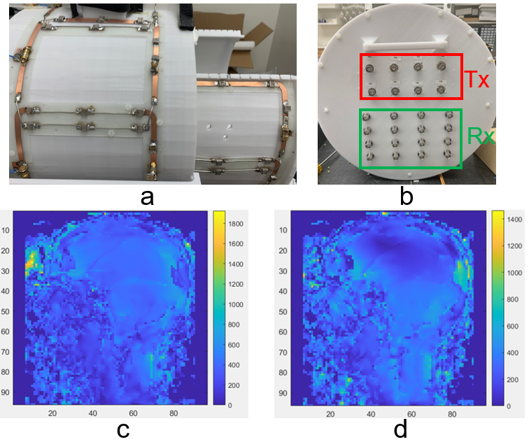
Figure 1. a) Coil layout in the
16-channel array; b) back plane of the 16-channel array where the BNC connectors
for the 8 transmit channels and the 16 receive channels are located; c) exemplary RF shimmed result for whole brain imaging; d) exemplar RF shimmed result for
cervical spinal cord imaging
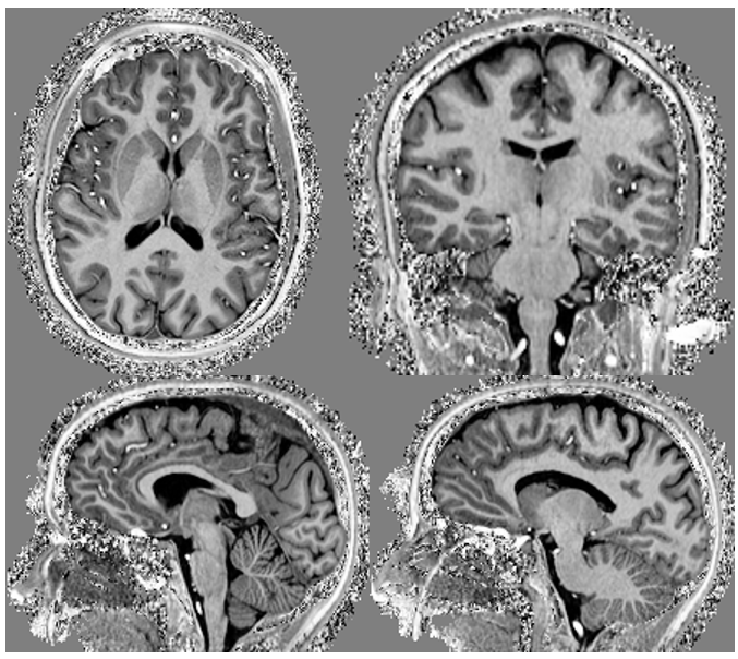
Figure 2. 1mm×1mm×1mm in vivo T1-weighted images
in axial plane (top left), coronal plane (top right) and two representative
slices in sagittal plane (bottom) acquired with the 3D MP2RAGE sequence
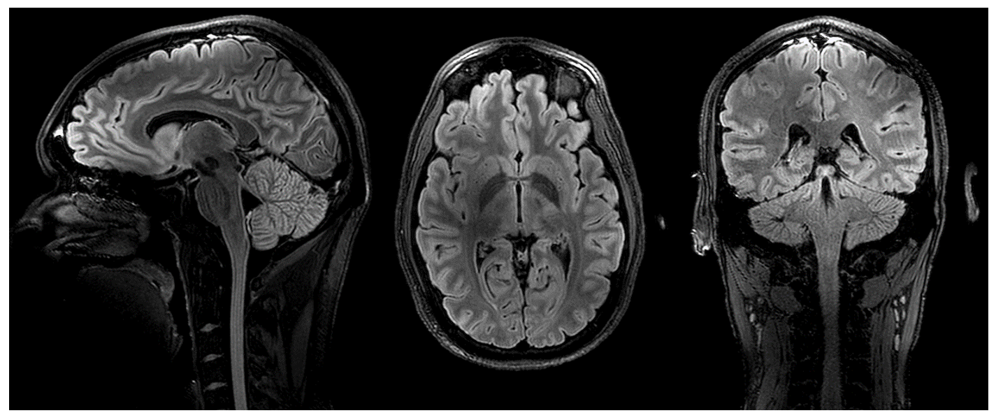
Figure 3 0.48mm×0.48mm×0.48mm FLAIR images
acquired with the 16-channel array in sagittal plane (left), transversal plane
(middle), and coronal plane (right) respectively
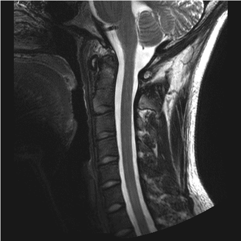
Figure 4. Highly spatially resolved (0.37mm ×
0.37mm) T2-weighted image of the cervical spinal cord in sagittal plane.
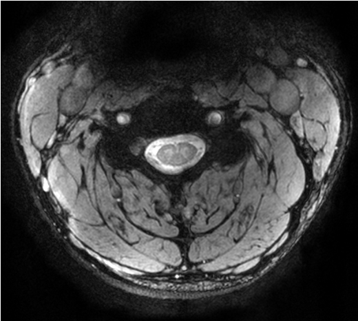
Figure 5. Highly spatially resolved (0.29mm ×
0.29mm) GRE image of the cervical spinal cord in axial plane
DOI: https://doi.org/10.58530/2023/1414