1412
Double-Row 16-element Folded-End Dipole Transceiver Array for Human Whole Brain Imaging at 9.4 T.1High-Field MR Center, Max Planck Institute for Biological Cybernetics, Tübingen, Germany, 2Biomedical Magnetic Resonance, University of Tübingen, Tübingen, Germany
Synopsis
Keywords: High-Field MRI, RF Arrays & Systems, Dipole antenna
Homogeneity and coverage of transmit (Tx) RF coils at ultra-high field (UHF,>7 T) can be improved by 3D RF shimming. This, however, requires using multi-row Tx-arrays. Dipole antennas provide unique simplicity and robustness while offering comparable Tx-efficiency and SNR to conventional loop designs. Single-row UHF dipole Tx-arrays for human head imaging have been previously described. Recently, we developed a novel type of dipole elements, a folded-end dipole, which improved the longitudinal coverage and specific absorption rate (SAR) efficiency. In this work, we developed, constructed, and evaluated a 16-element double-row transceiver folded-end dipole array for human whole-brain imaging at 9.4 T.Purpose:
To develop a double-row transceiver (TxRx) dipole array coil capable of 3D RF shimming for human whole brain imaging at 9.4 T.Introduction:
Homogeneity and coverage of the transmit (Tx) RF magnetic field, B1+, during human head imaging at ultra-high field (UHF, > 7T) can be improved by 3D RF shimming (1,2). This, however, requires using multi-row Tx-arrays (2-7). Examples of double-row 7T (3-5) and 9.4T (2,6,7) loop arrays have been described previously. Dipole antennas, suggested by Raaijmakers (8) provide unique simplicity and robustness while offering comparable Tx-efficiency and SNR to conventional loop designs. Single-row Tx and transceiver (TxRx) UHF dipole arrays for human head imaging have been previously described by multiple groups (9-12). Recently, we developed a novel type of dipole elements, a folded-end dipole (13,14), which helps to improve the longitudinal coverage and minimize the specific absorption rate (SAR) as compared to common dipoles. In this work, we developed, constructed, and evaluated a 16-element double-row (2x8) TxRx folded-end dipole array for human whole brain imaging at 9.4T. To the best of our knowledge, this is the first example of double-row TxRx dipole array developed for UHF human whole-brain imaging.Methods:
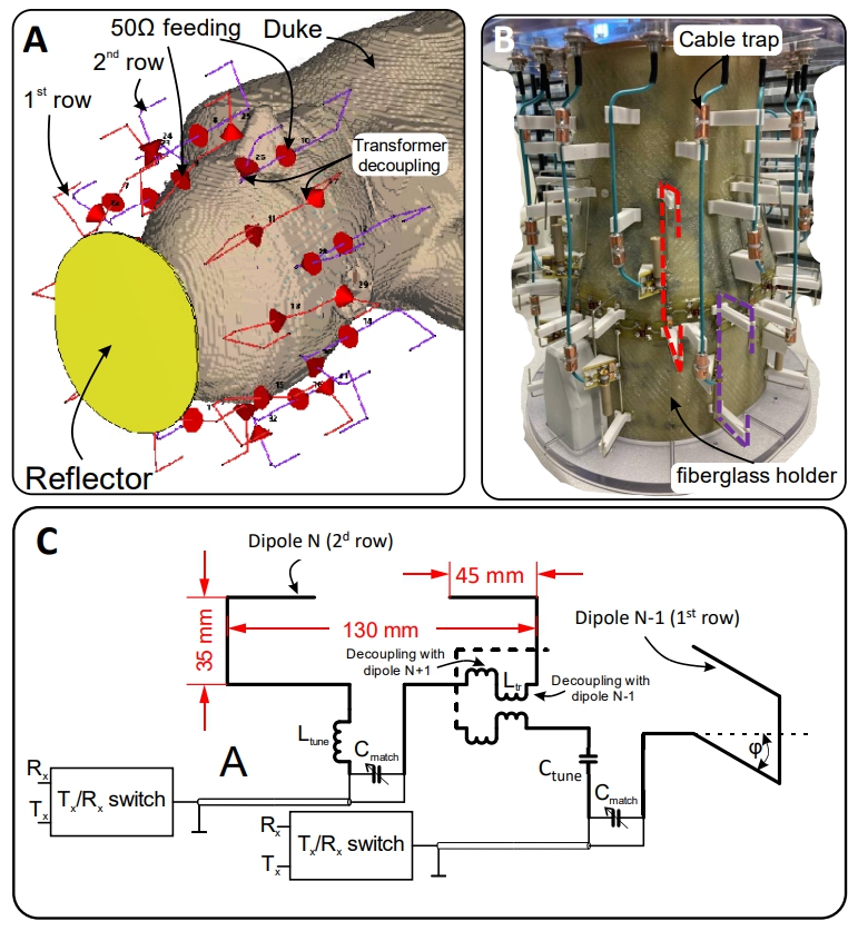
The 2x8 dipole array was placed on a fiberglass housing and measured 200 mm x 230 mm (width x height) and 215 mm in length. Fig.1 presents an electromagnetic (EM) simulation model (Fig.1A), photo (Fig.1B), and the schematic (Fig.1C) of the developed array. The array had no an RF shield. Local flat RF shield (”reflector”, Fig.1A) was added at the superior head location to improve the B1+ field in this area (14). Dipole were constructed using 1.5-mm copper wire. Adjacent dipoles located in different rows were decoupled by home-built transformers connected in series with the dipoles (Fig.1C). Fine tuning of transformer decoupling was performed by adjusting the distance between the windings. Before constructing, we numerically optimized the array geometry to improve Tx-efficiency (<B1+>/√P) and SAR-efficiency (<B1+>/√pSAR10g), where pSAR10g is peak SAR averaged over 10g of tissue. <B1+> was averaged over 130-mm transversal slab, which includes the majority of the brain. Homogeneity was evaluated as the standard deviation (SD) over the same volume. During optimization, we varied three parameters, i.e. overlapping between the 1st and 2d rows, length of the dipoles, and position of the reflector. Overlapping measured 25mm, 35mm, and 45mm. Length measured 126mm, 131mm, and 136mm. While varying the length, the position of the dipoles near the neck was fixed, the other dipoles’ ends were extended above the head by 20mm, 30mm, and 40mm, respectively. The reflector was placed at three different positions, i.e. aligned with the dipole ends (Position 0), moved by 30 mm (Position 30) and 60 mm (Position 60). For each variation, we evaluated Tx- and SAR-efficiencies for the quadrature circular polarized (CP) mode as well as for five RF shimmed modes produced by an addition of a phase shift between the rows varied from 20º to 100º in 20º-step (2). The phase shift of 0º corresponds to the CP mode. Electromagnetic (EM) simulations were performed using CST Studio Suite 2021 (Dassault Systèmes, Vélizy-Villacoublay, France) and the time-domain solver based on the finite-integration technique. We used two human voxel models, i.e. Duke and Ella.All data were acquired on a Siemens Magnetom 9.4T human imaging system. We compared the new array to an 8-element single-row (1x8) folded-end dipole array with the same total length (13). In-vivo B1+ maps of all modes were recorded using 3D satTFL(15) (TR=2.44ms, TE=0.75ms, GRAPPA 2x2, FA=2°/70°, matrix: 64x64x64, resolution 3.5mm isotropic). GRE and MPRAGE images with a phase shift of 60° were acquired. (MPRAGE: TI=1340ms, TR=3360ms, GRAPPA 2x2, matrix 264x264x224mm, resolution 0.8mm isotropic; GRE: TR=11ms, TE=7ms, GRAPPA 2x2, FA=5˚, matrix 264x264x224mm, resolution 0.8mm isotropic).
Results and Discussion:
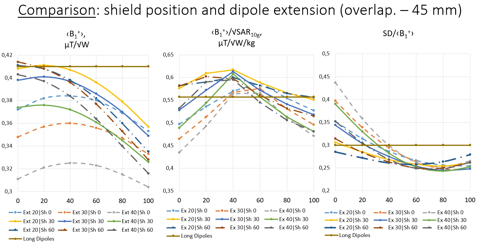
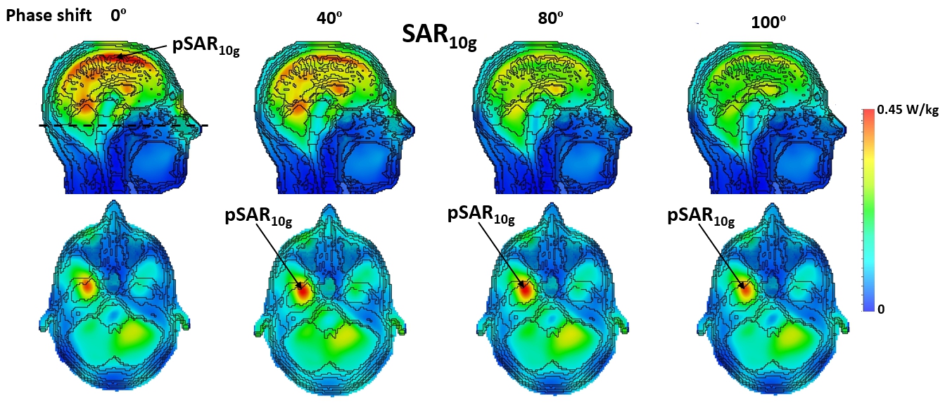
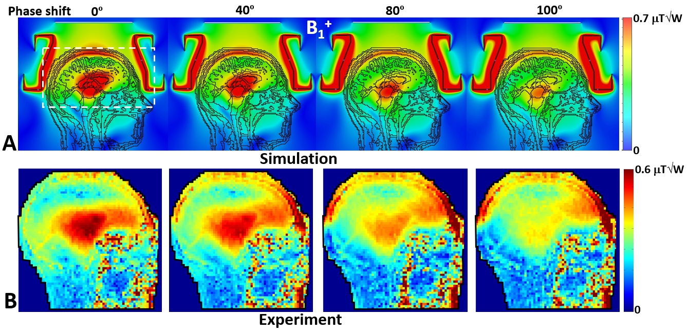
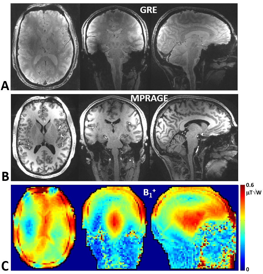
First, based on simulations, we chose the largest 45-mm overlapping, which provides the highest SAR-efficiency. It also allows increasing the dipole length and loading while keeping the same total length of the array. Then, we optimized other parameters. As an example, Fig.2 shows simulation results for arrays with 45-mm overlapping, three shield positions, and three extensions above the head. Based on these data, we chose the 2x8 array with the extension of 20mm and the shield positioned at 30mm. This design provides 11% higher SAR-efficiency, and 18% higher homogeneity than the 1x8 array. Fig.3 shows SAR10g maps simulated for the developed array loaded by the Duke voxel model at four different phase shifts between the rows. Fig.4 depicts simulated (Fig.4A) and experimental in vivo (Fig.4B) central sagittal B1+ maps obtained using the developed array with different phase shifts between the rows. As seen in the figure, phase shifts improve the homogeneity and longitudinal coverage. Finally, Fig.5 shows in-vivo human brain GRE and MPRAGE images, and corresponding B1+ maps obtained for the same male subject as in Fig.4 using the developed array.Conclusion:
We developed, constructed, and evaluated the 16-element double-row TxRx folded-end dipole array for human head imaging at 9.4T. The design is capable of 3D RF shimming and can be potentially used in parallel transmission (pTx). The array provides 11% higher SAR-efficiency, and 18% higher homogeneity than the folded-end dipole single-row array of the same length.Acknowledgements
Funding by the European Union (ERC Advanced Grant SpreadMRI, Number: 834940) is gratefully acknowledged. SG acknowledges a support by Russian Science Foundation (Project 21-19-00707).References
1) Mao W, Smith MB, and Collins CM. Magn Reson Med 2006;56:918-922.
2) Hoffmann J, Shajan G, Scheffler K, Pohmann R. Magn Reson Mater Phy 2014;27(5):373-386.
3) Adriany G, Van de Moortele P-F, Ritter J, et al. Magn Reson Med 2008;59:590-597.
4) Avdievich NI. Appl Magn Res 2011;41(2):483-506.
5) Gilbert KM, Belliveau J-G, Curtis ATet al. Magn Reson Med 2012;67:1487–1496.
6) Shajan G, Kozlov M, Hoffmann J, et al. Magn Reson Med 2014;71:870–879.
7) Avdievich NI, Giapitzakis IA, Bause J, et al. Magn Reson Med 2019;81(5):3392-3405.
8) Raaijmakers AJE, Ipek O, Klomp DWJ et al. Magn Reson Med 2011;66:1488-1497.
9) Chen G, Cloos M, Sodickson D, and Wiggins G.. Proceedings of 22d Annual Meeting of ISMRM, Milan, Italy 2014:621.
10) Clément J, Gruetter R, Ipek Ö. Magn Reson Med 2019;82(3):1229-1241.
11) Gilbert KM, Klassen LM, Mashkovtsev et al. NMR Biomed 2021;34(3):e4457.
12) Woo MK, DelaBarre L, Waks M, et al. Sensors 2021;21(21):7250.
13) Avdievich NI, Solomakha G, Ruhm L, et al. Magn Reson Med 2021;86(1):581-597.
14) Avdievich NI, Solomakha G, Ruhm L, et al. NMR Biomed 2021;34(8):e4541.
15) Bosch D, Bause J, Geldschläger O, Scheffler K. Magn Reson Med. 2023; 89: 322- 330.
Figures