1235
‘Reverse’ RF/B0 shimming coils1Vanderbilt University Institute of Imaging Science, Vanderbilt University Medical Center, Nashville, TN, United States, 2Department of Radiology and Radiological Sciences, Vanderbilt University Medical Center, Nashville, TN, United States
Synopsis
Keywords: Shims, Shims
In this work, we propose a reverse RF/B0 shimming coil design for ultrahigh field MRI without using any large bridge choke inductors. Our simulation and experimental results reveal that this design does not impair the RF performance, but would able to reduce the DC resistance/inductance/heating and also save precious space in RF/B0 shimming coils.Purpose
Integrated RF/B0 shimming coils can simultaneously receive signal and perform B0 shimming [1-2]. However, large chokes in RF/B0 coils increase the inductance/resistance of the DC loop and lead to unwanted power dissipation. They are also bulky when space is limited, such as in a multi-channel receive/shim array. Several designs have been proposed to remove the need for large bridge chokes, such as mono transmission lines [3-4] and shielded coaxial coils (SCC) [5]. However, mono transmission line resonators require special manufacturing and are not readily feasible for use as imaging coils in terms of size, geometry, or shape, and SCC operates in the 2nd resonant mode and has lower filling factors. In previous RF/B0 coil designs, the goal has been to form an additional DC path in a standard RF coil. Here we propose instead to form an additional RF resonator in a DC coil, i.e., design RF/B0 coil in a 'reverse' way.Methods
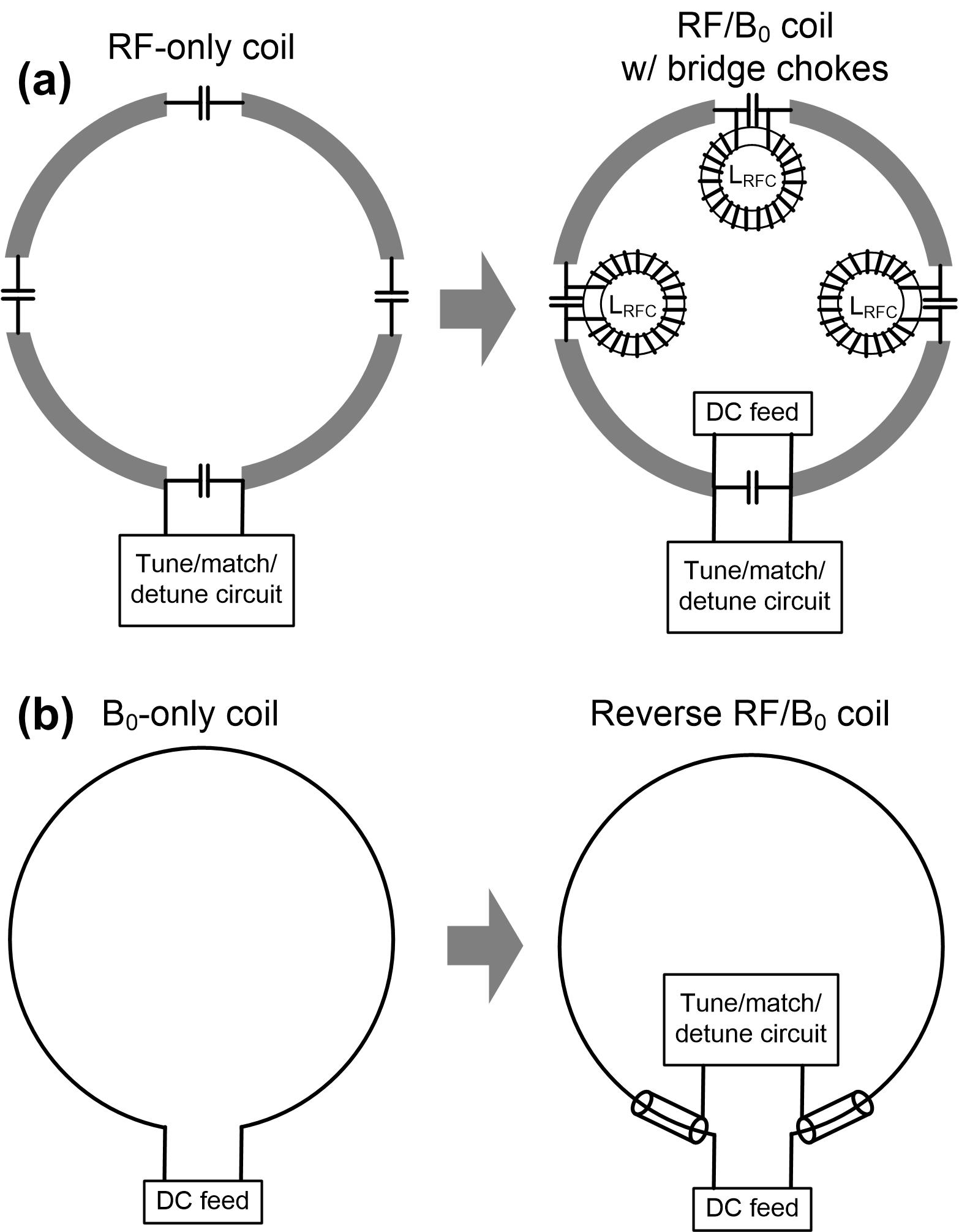
Concept and EM simulationFigure 1a illustrates how an RF-only coil evolves to become an RF/B0 coil. Figure 1b illustrates that a DC coil could turn into an RF/B0 coil (‘reverse’ design) by adding sleeve conductors to form an RF resonator. Obviously, the reverse coil has an unbroken DC loop and thereby does not require any bridge chokes. Electromagnetic (EM) simulations were performed with Ansys HFSS to evaluate the receive sensitivity (B1-/√power), an indicator of the SNR. Three coils with different sizes (diameters of 6 cm, 8 cm, and 10 cm) were investigated. For comparison, we also simulated conventional RF-only coils made of copper wire and multiple equally-distributed discrete capacitors.
Coil fabrication, bench tests and MR experiment
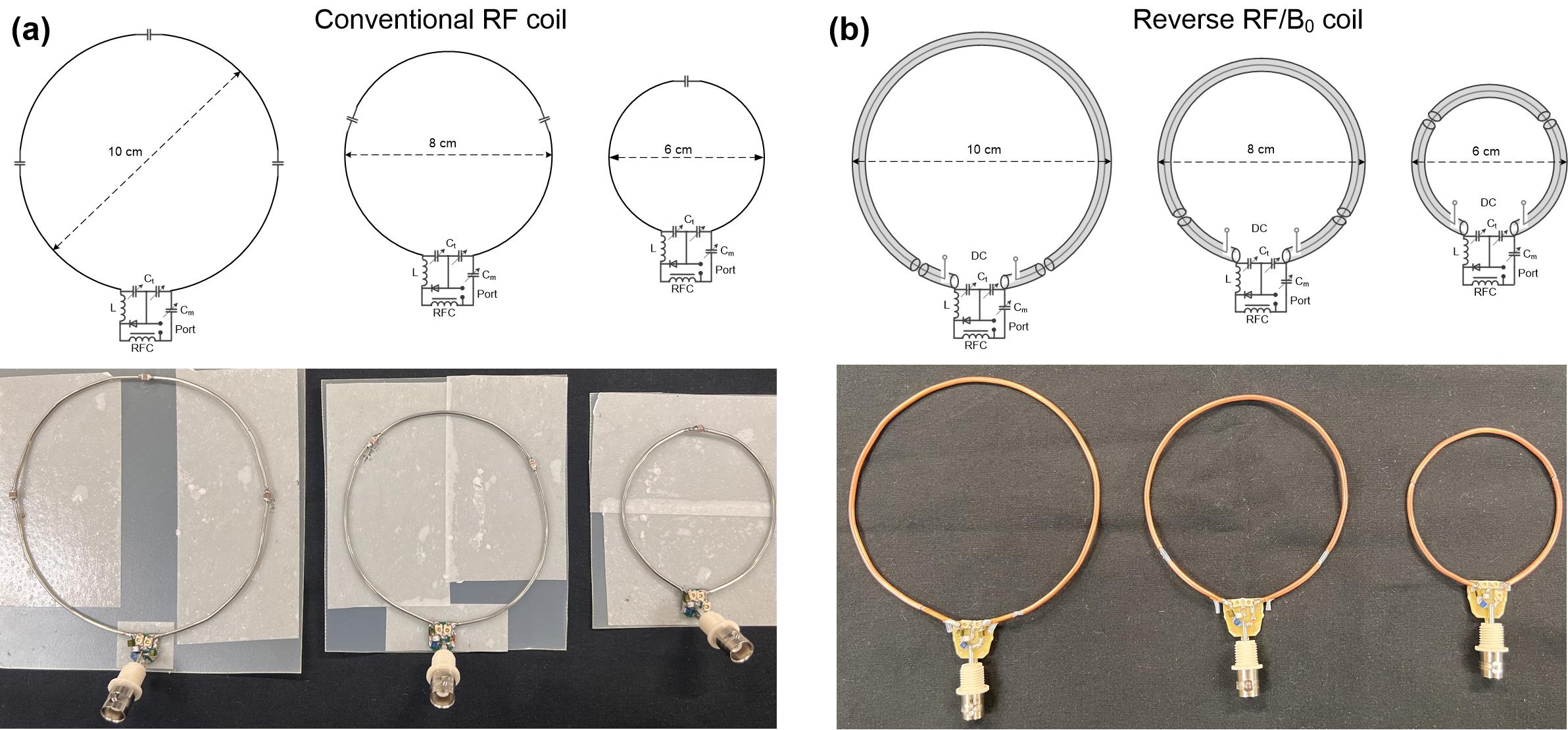
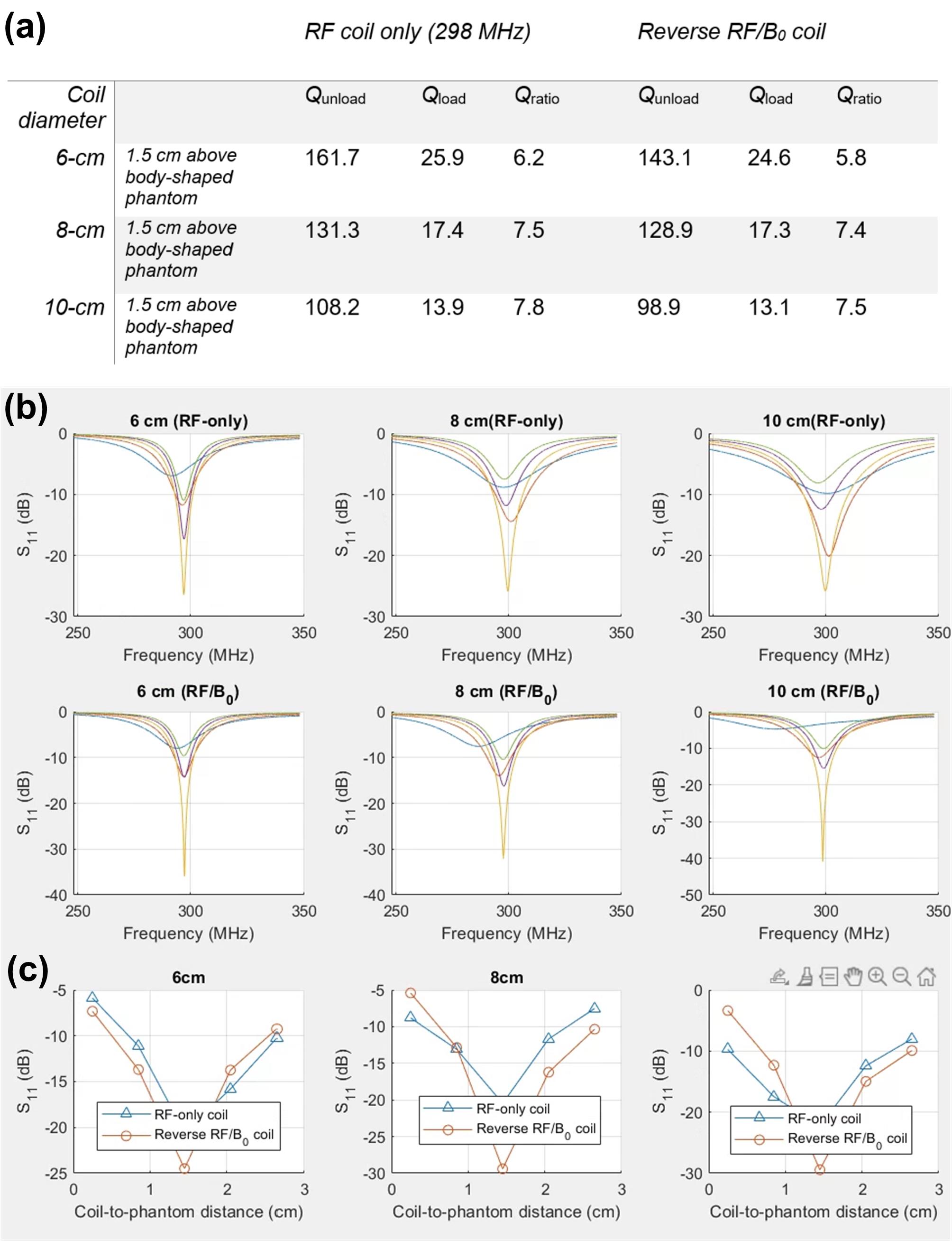
We built three reverse RF/B0 coils for 7T with different sizes (6 cm, 8 cm and 10 cm diameter), as shown in Figure 2a. The length of the sleeve conductor on each side of the reverse coil was chosen to be 5.5/2.5/0.8 cm for coils with diameters of 6/8/10 cm, respectively. For comparison, we built RF-only coils using 14-AWG wires and discrete capacitors, as shown in Figure 2b. All these coils are built for the receive-only purpose so they have a detune circuit to disable the coil during the Tx phase. We measured all coils' unloaded Q-factors in free space and loaded Q-factors when they are placed 1.5 cm above a body-shaped phantom. We measured the coil robustness vs. different loading conditions by recording the S11 changes when moving the coil closer or further away from the phantom. We also measured the central axial SNR map on a bottle phantom with all these coils. The SNR was calculated from low-flip-angle GRE images measured on a 7T Philips whole-body scanner.
Results
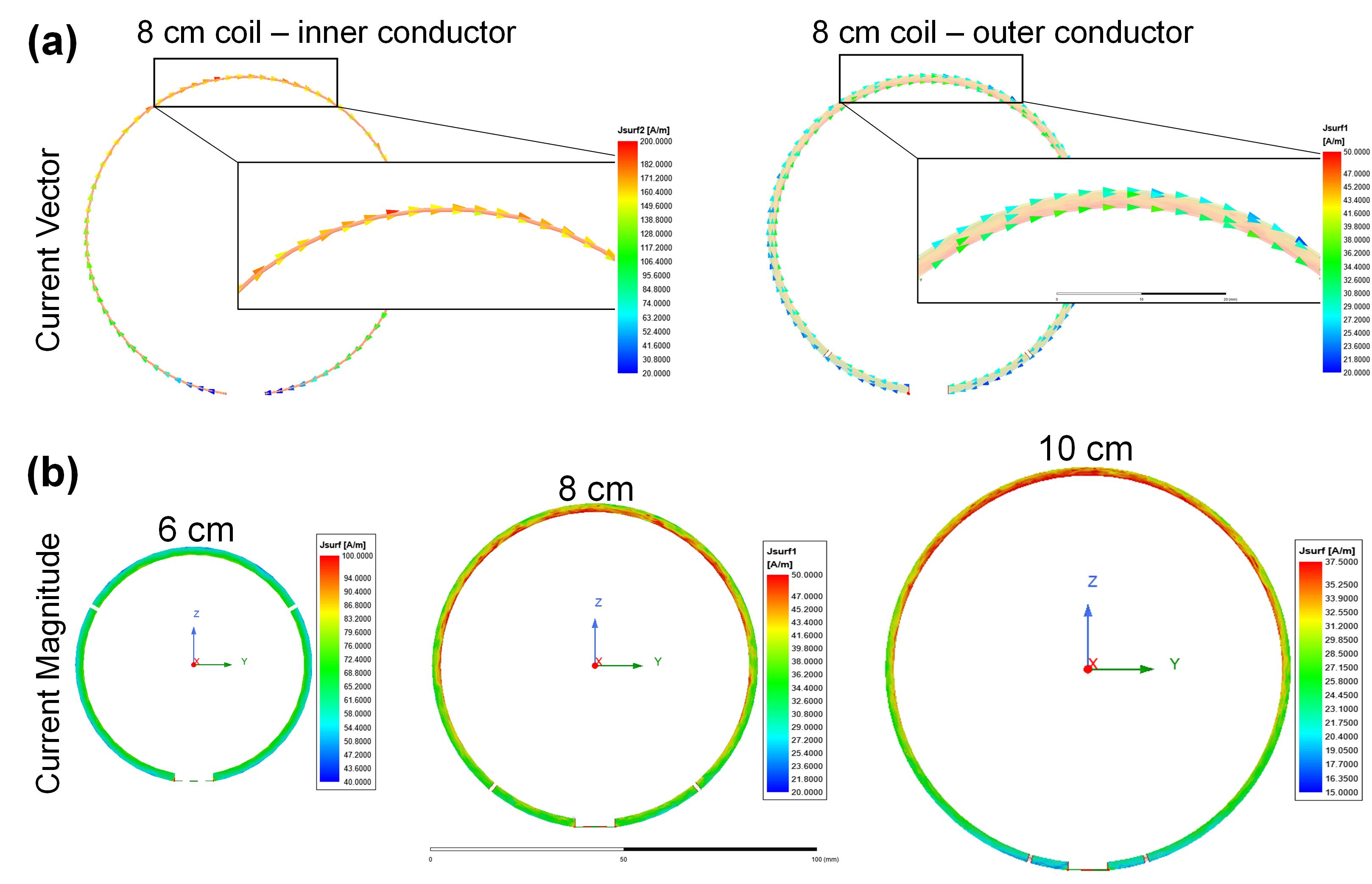
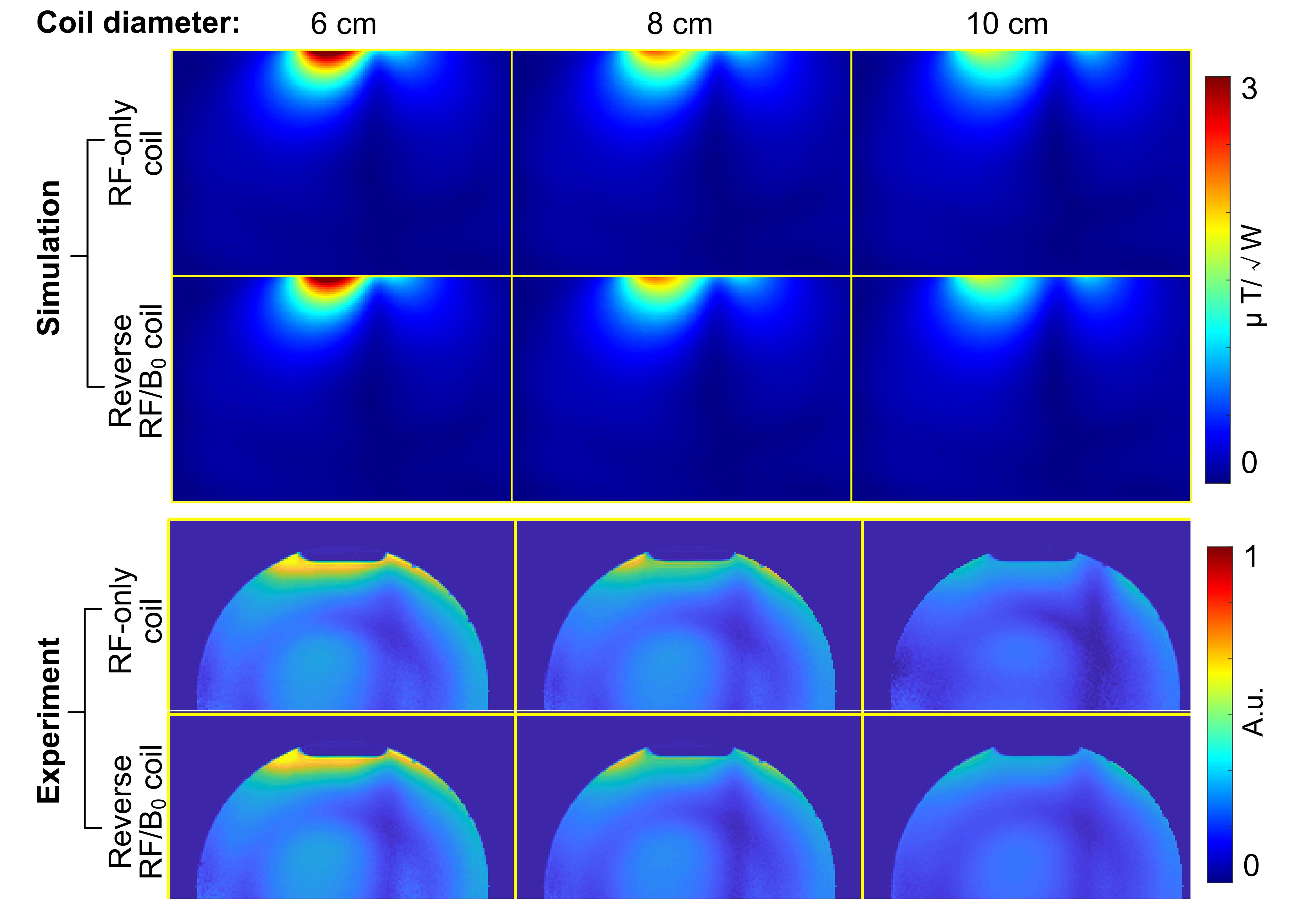
Figure 3a plots the vector of currents along the inner and outer conductors. As expected, the coil works in common mode and the currents flowing along the inner and outer conductors are in the same direction (both clockwise). This is also evidenced by the Q-factor comparison (provided later). Figure 3b shows the magnitude of the current along the outer conductors. The current distribution becomes more uniform as the coil size reduces. For the 6-cm-diameter reverse coil, the current is already as uniform as that of a conventional RF-only coil with multiple discrete capacitors. This is also expected since the smaller coil would require larger capacitance (i.e., longer sleeve conductors). The simulated B1- efficiency results also revealed that the reverse coil exhibits the same performance as that of an RF-only coil (Figure 4a). Consistent with the simulation results, the reverse RF/B0 shimming coil show the same SNRs as those of conventional RF-only coils in the MRI experiments (Figure 4b).Figure 5a compares the measured unloaded and loaded Q-factors. There are almost no drops in either unloaded Q factors or Q ratios, which further demonstrates that there would be no additional coil loss or coil sensitivity penalty by employing the reverse design. Figure 5b and 5c show the coil impedance robustness vs. the loading scenarios. The coil robustness was not significantly impaired by asymmetrical capacitance distribution in each reverse RF/B0 coil. Even for the 10-cm-diameter coil where the total coaxial capacitance near the feed port is ~0.4 pF, its coil impedance showed notable changes only when they were moved extremely close to the sample.
Discussion and Conclusion
We propose a novel choke-free RF/B0 shimming coil by reversely considering the combination of DC and RF paths. We found the reverse RF/B0 coil does not impair the RF performance, in terms of coil sensitivity and coil robustness. This will reduce the footprint of RF/B0 coils as well as the inductance/resistance and thus power dissipation, without sacrificing SNR or coil robustness. The coils may also enable faster B0 shim switching.Acknowledgements
This work was supported by NIH R01 EB 031078.References
1. Han H, Song AW, Truong TK. Integrated parallel reception, excitation, and shimming (iPRES). Magn Reson Med. 2013; 70: 241– 247.
2. Stockmann JP, Witzel T, Keil B, et al. A 32‐channel combined RF and B0 shim array for 3T brain imaging. Magn Reson Med. 2016; 75: 441– 451.
3. Stara R, Pendse M, Stockmann J, Rutt B. Monolithic transmit line resonator as a combined B1/B0-shim coil element. InProceedings of the 25th Annual Meeting of ISMRM, Honolulu, Hawaii, USA 2017 (p. 968).
4. Bratch A, Radder J, Jenkins P, Jungst S, Metzger G, Ugurbil K, Adriany G. Overlapped Monolithic Transmission Line Resonator Receiver and B0 Shim Array For Functional Imaging of the Human Temporal Lobe. Proc 27th Annu. Meet. Int Soc Magn Res Med. 2019:3.
5. Boer VO, Pedersen JO, Andreasen H, Güler S, Zhurbenko V, Stockmann J, Zivkovic I, Petersen ET. Shielded coaxial cable coils for transmit, receive and B0 shimming in a 7T neck array. InProceedings of the 29th annual meeting of ISMRM 2021 (Vol. 29, p. 3109).
Figures