1234
Prospective Compensation of Second-order Concomitant Fields in a High-performance Gradient System using a Second Order Harmonic Shim Coil1GE Global Research, Niskayuna, NY, United States
Synopsis
Keywords: Gradients, Gradients, Concomitant Field Correction
The use of higher-performance gradient coils results in stronger second-order concomitant magnetic fields, which can lead to image artifacts such as signal dropout, blurring, and phase errors that cannot be corrected by pre-emphasis of gradient waveforms and/or radio frequency modulation alone. We have developed an axially symmetric second-order field coil that is insertable, and demonstrate its ability to prospectively correct the additional phase generated by second-order concomitant fields in 2D phase contrast and spiral-out gradient echo imaging in a 3.0 T high-performance head-gradient (MAGNUS) system.Introduction
High-performance gradient systems combine high gradient amplitudes (Gmax) and high maximum slew rates (SRmax) to enable rapid and high-resolution magnetic resonance imaging (MRI) for various applications1–3. High-quality diffusion, perfusion and functional MRI have been demonstrated in the MAGNUS (GE Research, Niskayuna, NY, USA) asymmetric gradient system that simultaneously delivers a Gmax and SRmax of 200 mT/m and 500 T/m/s, respectively, using a 620 A/1400 V gradient driver in a clinical whole‐body 3.0 T magnet1,4–7. However, utilization of higher Gmax at a given main magnetic field strength is accompanied by stronger second-order concomitant gradient (SOCG) fields that cannot be corrected by pre-emphasis of gradient waveforms and/or radio frequency (RF) modulation alone8,9. Such fields can lead to signal dropout and phase errors in phase contrast (PC) MRI, as well as in-plane and through-plane blurring in spiral imaging. Most published methods for the correction of SOCG rely on sequence modification and image processing10,11. Here, we report the use of an axially symmetric coil for prospective correction of SOCG in PC and 2D spiral-out gradient echo imaging at 3.0 T.Materials and Methods
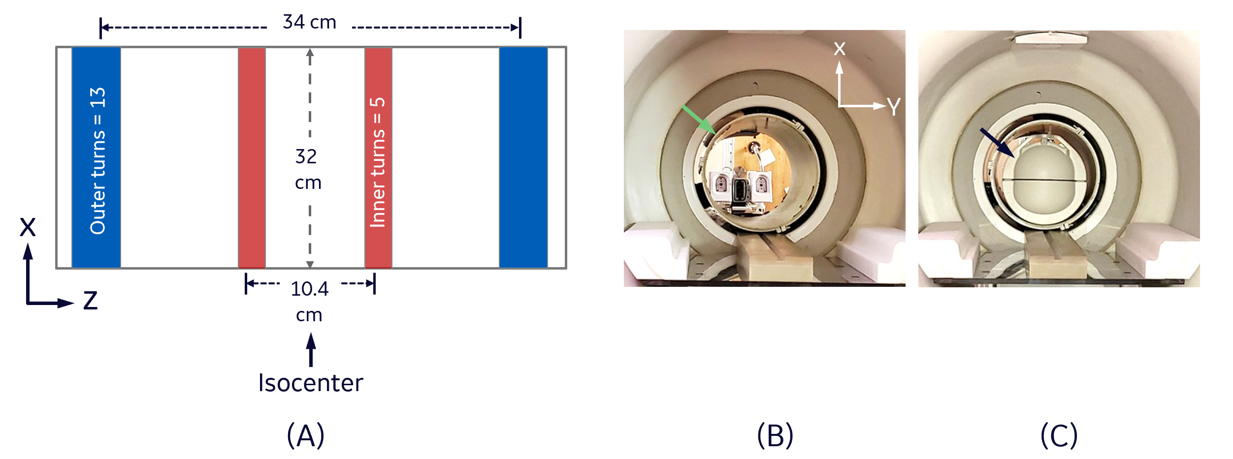
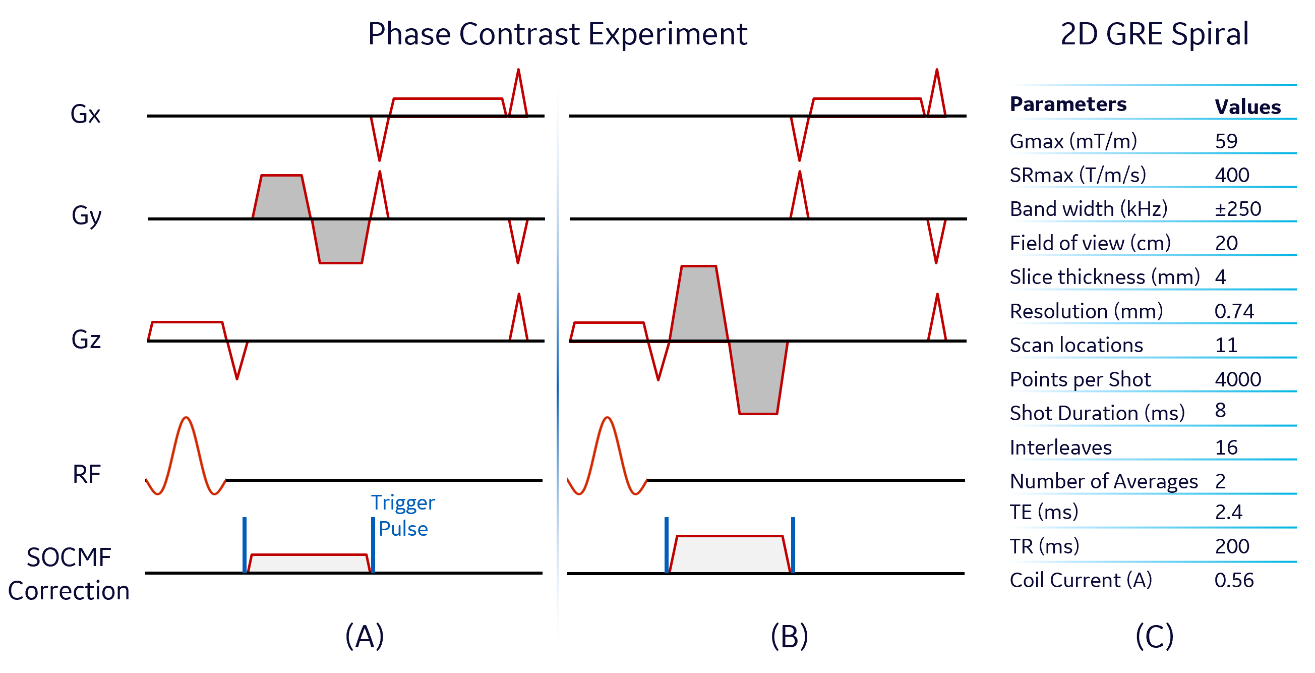
Second Order Correction Coil Design and Setup: An axi-symmetric second order $$$($$$z2$$$-($$$x2$$$+$$$y2$$$)/$$$2$$$)$$$ magnetic field (B-field) coil was designed by nulling the zeroth and fourth order Taylor’s expansion terms of the axial B-field created by concentric circular loop coils arranged on the surface of a 32 cm-diameter cylindrical former in a mirror-symmetric manner. The diameter of the copper wire used for the coil construction was 1.67 mm, and other design parameters are detailed in Figure 1A. The correction coil was inserted inside the head transmit/receive coil of the MAGNUS system, and was driven by an audio amplifier (AE Techron 7220$$$–$$$Ekhart, IN, USA), which received a unipolar pulsed voltage signal from a signal generator (Tektronix AFG 3252$$$–$$$Beaverton, OR, USA) triggered by the scanner (Figure 1B and 1C).Simulation and Phantom Experiments: The B-field inside the designed correction coil was calculated using the Biot-Savart Law on a 3D grid of 1$$$\times$$$1$$$\times$$$1 mm3 spatial resolution. A pickup coil was used to experimentally sample the B-field along the axis of the coil while applying an alternating current of 0.5 A. Imaging experiments were carried out at 3.0 T using the MAGNUS system with firmware patches for zeroth and first order eddy current and concomitant gradient fields correction12,13. The correction coil was used to null phase errors (non-zero zeroth moment) due to SOCG in single-sided PC MRI with bipolar gradients in the slice selection direction of a coronal and axial acquisition. For the coronal acquisition (Figure 2A), the correction coil current, Gmax, SRmax and plateau time of each bipolar gradient lobe were 0.23 A, 59 mT/m, 400 T/m/s and 1 ms respectively. The axial PC experiment was identical to the coronal acquisition except that the correction current and Gmax of the lobes were increased to 0.50 A and 150 mT/m respectively (Figure 2B). A silicone gel phantom was used for both PC experiments, and other acquisition parameters include slices$$$=$$$3, TE/TR$$$=$$$6.6/105 ms and field of view$$$=$$$20 cm. An acquisition with zero amplitude bipolar gradients was used to remove background phase from the PC acquisitions. Additionally, the correction coil was used to reduce blurring artifacts due to SOCG generated during readout in a 2D multi-slice gradient echo (GRE) MRI with spiral-out readout. A 10 cm-diameter American College of Radiology phantom was used for the 2D-GRE experiment and the scan parameters are summarized in Figure 2C. SOCG was calculated as previously described:10
$$
\label{eq:decoder}
\mathrm{SOCG} \simeq \frac{\mathrm{G_{z}}^{2}}{8\mathrm{B}_{0}}\mathrm{x}^{2}+\frac{\mathrm{G_{z}}^{2}}{8\mathrm{B}_{0}}\mathrm{y}^{2}+\frac{\mathrm{G_{x}^{2}+G_{y}^{2}}}{2\mathrm{B}_{0}}\mathrm{z}^{2}-\frac{\mathrm{G_{x}G_{z}}}{2\mathrm{B}_{0}}\mathrm{xz}-\frac{\mathrm{G_{y}G_{z}}}{2\mathrm{B}_{0}}\mathrm{yz}
\tag{1}
$$
The current amplitude in the correction coil was empirically tuned to best cancel the SOCG effect in each experiment.
Results and Discussions
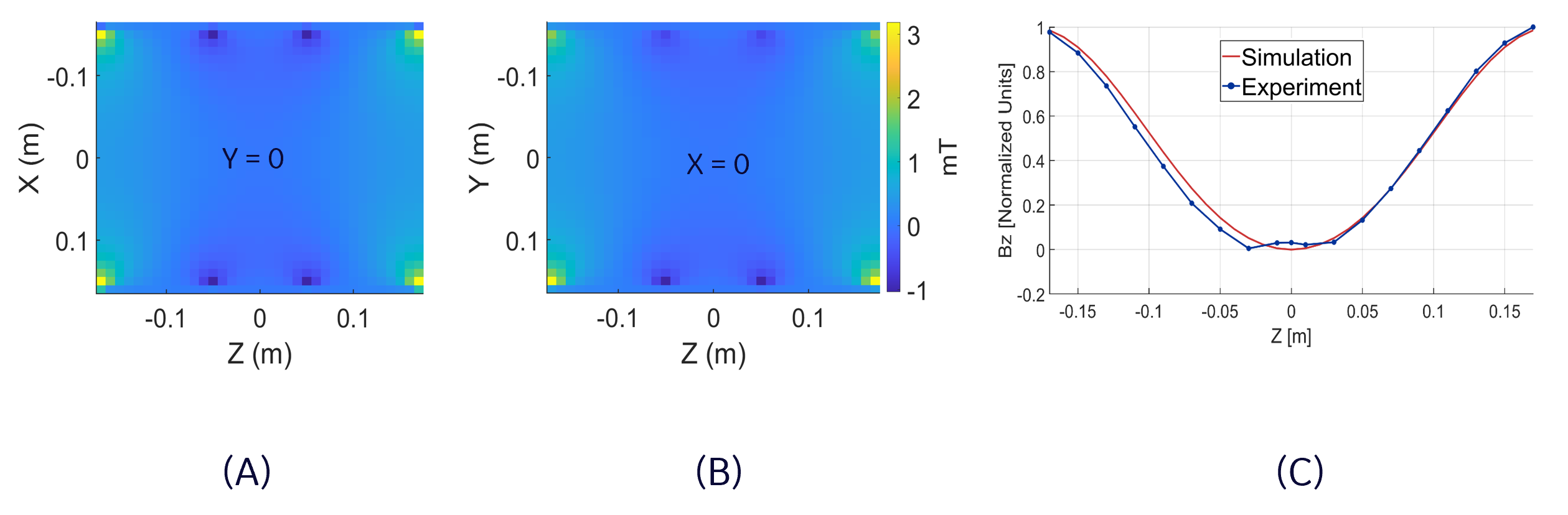
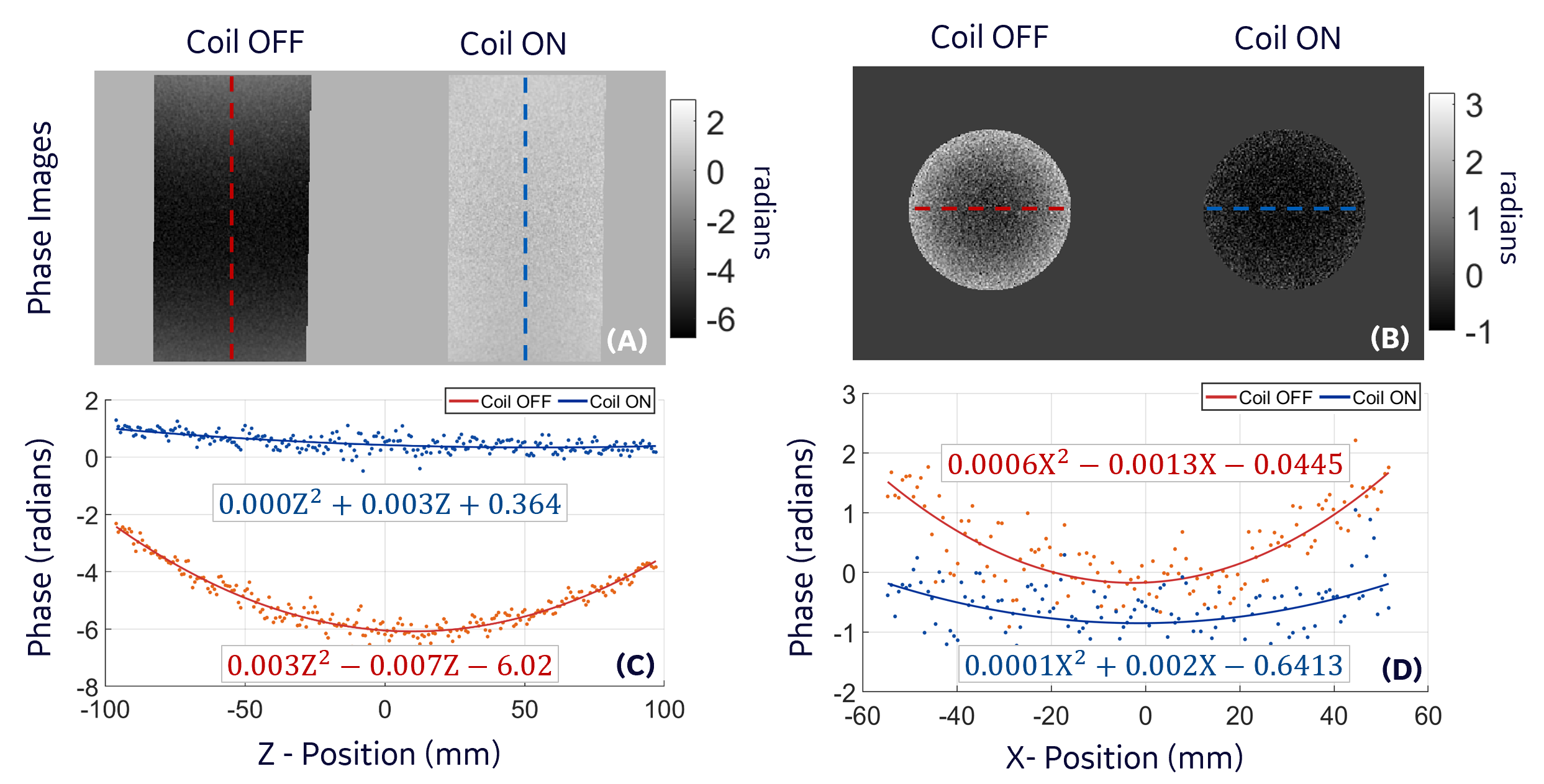
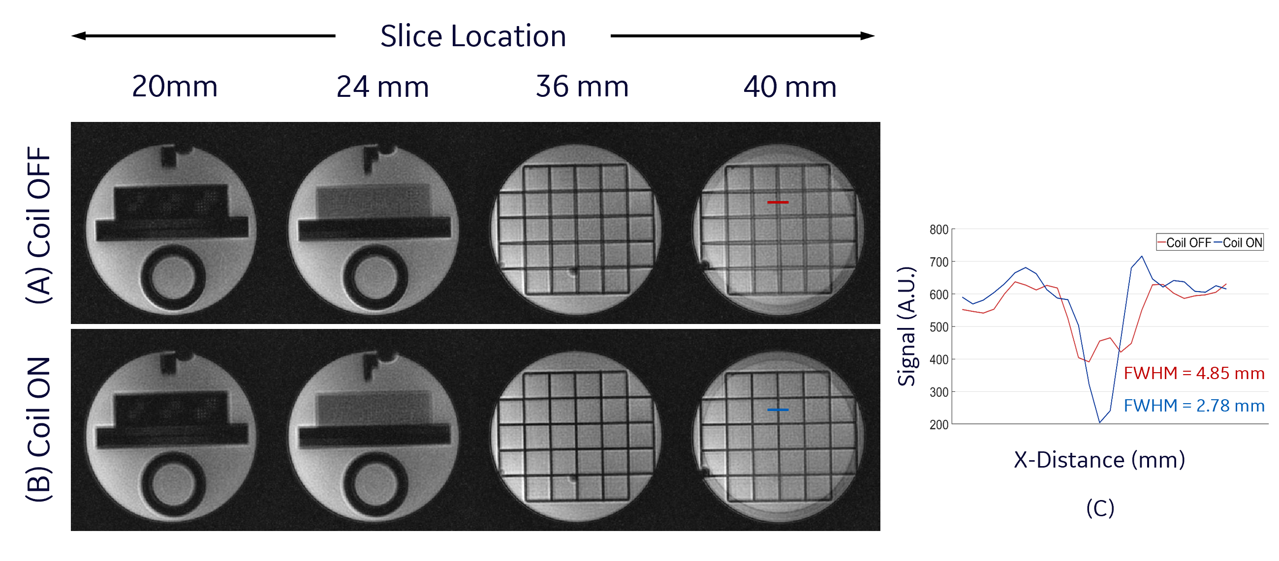
Figure 3A and 3B show the quadratic dependence of the simulated correction coil B-field on z location. The measured B-field along the axis of the coil showed good agreement with simulation (Figure 3C). The correction coil B-field reduced the SOCG phase accrued in the coronal and axial PC acquisition by 100% and 83% respectively. This reduction is indicated in the fit to the experimental data by the coefficients of z2 and x2 for the coronal and axial acquisitions respectively (Figure 4). The remaining linear and constant components of the phase can be eliminated by frequency shifting or retrospectively during image reconstruction. The in-plane blurring in 2D GRE spiral-out imaging due to SOCG phase accrual was substantially reduced by the correction coil (Figure 5). As expected, the amount of blurring is highest in slices that are farthest from the isocenter of the gradient (Figure 5A). The width of the line profile on the images at z$$$\rm{=}$$$40 mm demonstrates 42.7% reduction in blurring and substantial increase in contrast when the correction coil was turned on (Figure 5C). The z2-dependent B-field generated by the correction coil also has x2 and y2 dependence (to satisfy Laplace equation) that can cause other phase errors in 3D imaging, which suggests the need for an additional (x2$$$-$$$y2) coil and retrospective correction for a more complete SOCG compensation on all three axes.Conclusion
A custom-built SOCG correction coil has been used to prospectively correct phase accruals due to SOCG on single-sided 2D PC and spiral-out GRE MRI in the MAGNUS high performance gradient system.Acknowledgements
This work was supported by CDMRP W81XWH-16-2-0054, and this presentation does not necessarily represent the official views of the funding agency. We also acknowledge the help of Eric Fiveland for helping with 3D printing of parts needed for coil construction.References
1. Foo, T. K. F. et al. Highly efficient head-only magnetic field insert gradient coil for achieving simultaneous high gradient amplitude and slew rate at 3.0T (MAGNUS) for brain microstructure imaging. Magnetic Resonance in Medicine 83, 2356–2369 (2020).
2. Setsompop, K. et al. Pushing the limits of in vivo diffusion MRI for the Human Connectome Project. Neuroimage 80, 220–233 (2013).
3. Weiger, M. et al. A high-performance gradient insert for rapid and short-T2 imaging at full duty cycle. Magn Reson Med 79, 3256–3266 (2018).
4. Abad, N. et al. Brain Microstructure Imaging with Ultrahigh B-Encoding using MAGNUS High Performance Gradients. in ISMRM 2022 Annual Proceedings (2022).
5. Shih, R. et al. Initial Clinical Experience with MAGNUS Ultra-High-Performance Gradient Coil for Diffusion Microstructure Imaging of Intracranial Pathology. in ISMRM 2022 Annual Proceedings (2022).
6. Zhu, A. et al. Characterizing Restricted Diffusion in Pre-/Post- treatment Gliomas Using Time-dependent Diffusion MRI at Ultra-high-gradient Human 3.0T. in ISMRM 2022 Annual Proceedings (2022).
7. Ajala, A. et al. 3D Pseudo-Continuous Arterial Spin Labeling Acquisition using a High-Performance Gradient System: A Scan Time and Image Quality Assessment. in ISMRM 2022 Annual Proceedings (2022).
8. Tao, S. et al. Gradient Pre-Emphasis to Counteract First-Order Concomitant Fields on Asymmetric MRI Gradient Systems. Magn Reson Med 77, 2250–2262 (2017).
9. Weavers, P. T. et al. B0 concomitant field compensation for MRI systems employing asymmetric transverse gradient coils. Magn Reson Med 79, 1538–1544 (2018).
10. Bernstein, M. A. et al. Concomitant gradient terms in phase contrast MR: analysis and correction. Magn Reson Med 39, 300–308 (1998).
11. King, K. F., Ganin, A., Zhou, X. J. & Bernstein, M. A. Concomitant gradient field effects in spiral scans. Magnetic Resonance in Medicine 41, 103–112 (1999).
12. Tao, S. et al. The Effect of Concomitant Fields in Fast Spin Echo Acquisition on Asymmetric MRI Gradient Systems. Magn Reson Med 79, 1354–1364 (2018).
13. TAO, S., TRZASKO, J. D., Shu, Y., WEAVERS, P. T. & BERNSTEIN, M. A. Systems and methods for concomitant field correction in magnetic resonance imaging with asymmetric gradients. (2016).
Figures