1230
Modeling of Gradient-Induced Magnet Heating using Equivalent Current Surface and Multi-Physics Finite-Element Methods
Alexander Bratch1,2, Peter B. Roemer3, Gregor Adriany2, Kamil Ugurbil2, and Brian K. Rutt1
1Department of Radiology, Stanford University, Stanford, CA, United States, 2Center for Magnetic Resonance Research (CMRR), Department of Radiology, University of Minnesota, Minneapolis, MN, United States, 3Roemer Consulting, Lutz, FL, United States
1Department of Radiology, Stanford University, Stanford, CA, United States, 2Center for Magnetic Resonance Research (CMRR), Department of Radiology, University of Minnesota, Minneapolis, MN, United States, 3Roemer Consulting, Lutz, FL, United States
Synopsis
Keywords: High-Field MRI, High-Field MRI
With increasing prevalence of ultra-high field magnets and high-performance gradients, it is important to understand gradient-induced magnet heating, which can yield significant helium boil-off. Here, we propose a method to model this effect requiring no knowledge of gradient coil construction. Using measured gradient stray fields, we construct equivalent current surface models of gradient coils that can be input into finite element model of magnet systems to predict the deposited energy. We validate this equivalent current surface method using a gradient with a known winding pattern and further validate the energy deposition models by measuring power deposition in a 7T magnet.Introduction
It is well known that gradient activity can deposit significant energy into a superconducting magnet cryostat, particularly at higher gradient frequencies and higher B0 field strength1. This results from time-varying gradient stray fields producing a cascade of mechanical vibrations propagating through the conductive magnet structures. This energy deposition can lead to increased liquid helium boil-off, even to the point of quench. With the growing prevalence of both UHF magnets and high-performance gradients, it is critically important to understand this energy transfer mechanism. While basic elements of magnet construction can be relatively easily measured or inferred, details of gradient coil design and construction are not typically known or provided by the manufacturer.Here, we propose a methodology for analyzing gradient-magnet interactions which requires no knowledge of gradient construction, but rather uses an equivalent current surface (ECS) to represent the gradient coil exterior fields, derived from simple field measurements. Using stray field measurements along one or more Z-profiles, we construct an ECS for each gradient axis which is then used as input to a multi-physics finite-element model to assess the deposition of energy into a given magnet model. We validated these new modeling methods in several ways including against experimentally measured magnet heating data.
Methods
To derive an ECS model for a given gradient coil, we measured stray field profiles along Z at 5mm increments and at a radius just outside the coil’s outer surface, using a field sensor (MLX90393, Melexis, Belgium) and measurement apparatus. A weighted sum of sine or cosine current basis functions was then fit to these measurements to describe the current flowing on the ECS cylinder. The ECS radius was chosen to be larger than the coil outer radius but smaller than the field measurement radii (Figure 1). The equivalent current surfaces derived in this way for gradient coils of interest were used to define the stray fields that served as electromagnetic input to a multi-physics model of magnet heating.We compared magnetic fields produced by the ECS to those obtained by Biot-Savart calculation from a known winding pattern (our recently-built LH7 head gradient coil). We also evaluated the fields generated by the ECS for consistency with Maxwell’s equation as follows: we fit the basis functions using only one (e.g. Bz) component of the measured fields and then compared radial and transverse components of field generated by the ECS to the measured radial and transverse fields.
Multi-physics finite-element simulations were performed using COMSOL v6.0 (COMSOL Inc, Burlington MA). We built FEM models of various magnets, with particular attention paid to the innermost layers of the cryostat (warm bore, thermal shields, helium vessel inner bore, magnet winding former) (Figure 2). Dimensions and material properties of these cylindrical structures were obtained for the Agilent 7T AS 900 magnet installed in our lab. We first generated an ECS for the whole-body gradient coil installed in this magnet and then used this ECS to derive simulated power deposition profiles. Experimental power deposition profiles were derived by applying 3mT/m amplitude sinusoidal Z-gradient waveforms at frequencies between 500 and 3000 Hz and measuring the power drop in the LHe heater that forms part of the zero-boil-off control system2.
Results
Biot-Savart calculations from the LH7 winding pattern matched stray field profiles calculated from the ECS extremely well (Figure 3A) with peak field errors less than 0.02 µT/A, or about 3% of the peak fields found on that profile (Figure 3B).For the LH7 gradient, we could accurately predict the measured radial and tangential field components from the ECS fits to the measured Z component. For example, the maximum error between predicted and measured Br fields was about 0.1µT/A (ignoring lead contamination) compared to a peak Br field of about 0.6µT/A, demonstrating that the current-surface-generated fields conform to Maxwell’s equations and predict measured field profiles reasonably well (Figure 4).
Plots of normalized modeled and measured magnet heating profiles show a good match, with peak power deposition occurring near 2kHz in both cases although the measured data show relatively larger values at lower and higher frequency ranges (Figure 5A). Plots of absolute modeled and measured magnet heating profiles also show a good match, with simulated power peaking within a factor of two of the measured peak power deposition (Figure 5B).
Discussion and Conclusions
We have developed and demonstrated a method for assessing gradient-induced magnet heating that requires minimal knowledge of the underlying gradient design and construction. Using a small number of measured stray field profiles, equivalent current surfaces can be generated which accurately predict the stray field behavior of a gradient coil. Use of these ECSs with a multi-physics FEM model of gradient-magnet interaction yields magnet heating profiles which match experimentally-derived profiles with good accuracy. Our model makes a number of simplifying assumptions and to date the model does not consider any direct mechanical coupling between the gradient and the magnet; these and other approximations likely explain the remaining discrepancies between simulations and experimental measurements. On balance, the presented methodology is very promising and will assist in the definition of safe operating limits as well as in the development of new gradient technologies designed to minimize magnet heating.Acknowledgements
The authors would like to acknowledge research support from NIH U01 EB025144 and NIH R01 EB025131.References
1Dietz, Peter, Franz Schmitt, and Jürgen Hennig. "Gradients in ultra high field (UHF) MRI." In High-Field MR Imaging, pp. 27-40. Springer, Berlin, Heidelberg, 2012.
2Boulant, Nicolas. “Progress on the commissioning of the CEA 11.7T: Gradient-Magnet Interaction test results”. Talk presented at the ISMRM MR Engineering Study Group virtual meeting, 2021.
Figures
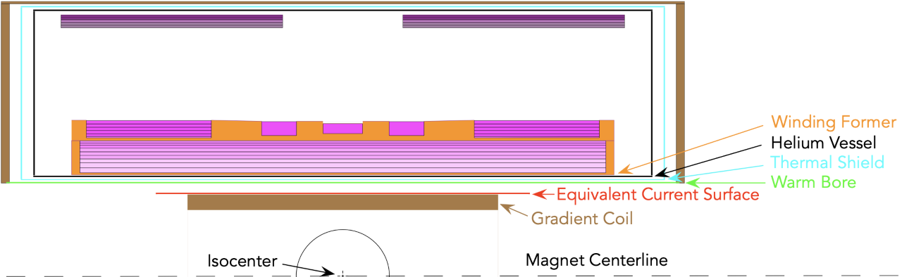
Figure 1. Longitudinal cross section through
magnet/cryostat (upper half only), showing main field homogeneity region (black
half circle), body gradient coil (brown), equivalent current surface (red),
magnet warm bore (green), thermal shield (cyan), helium vessel (black), magnet
winding former (orange), magnet windings (various shades of pink).
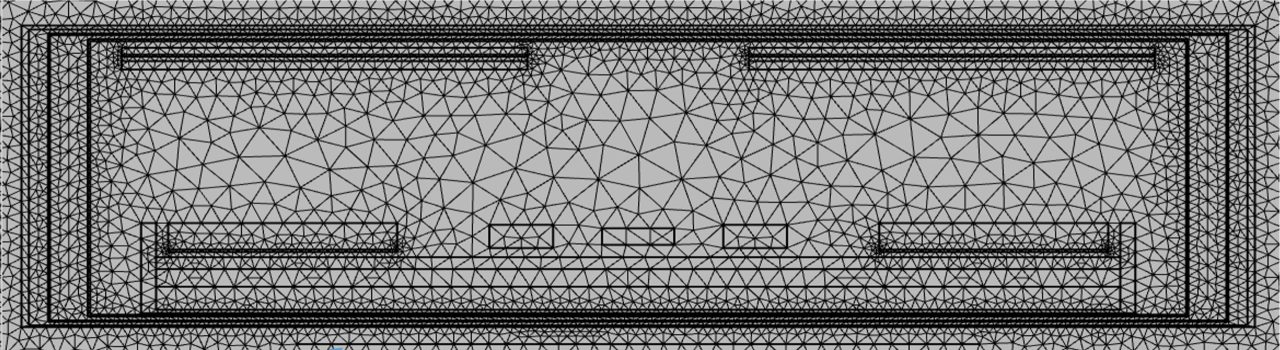
Figure 2. COMSOL
finite-element meshing of magnet/cryostat structures as well as equivalent
current surface.
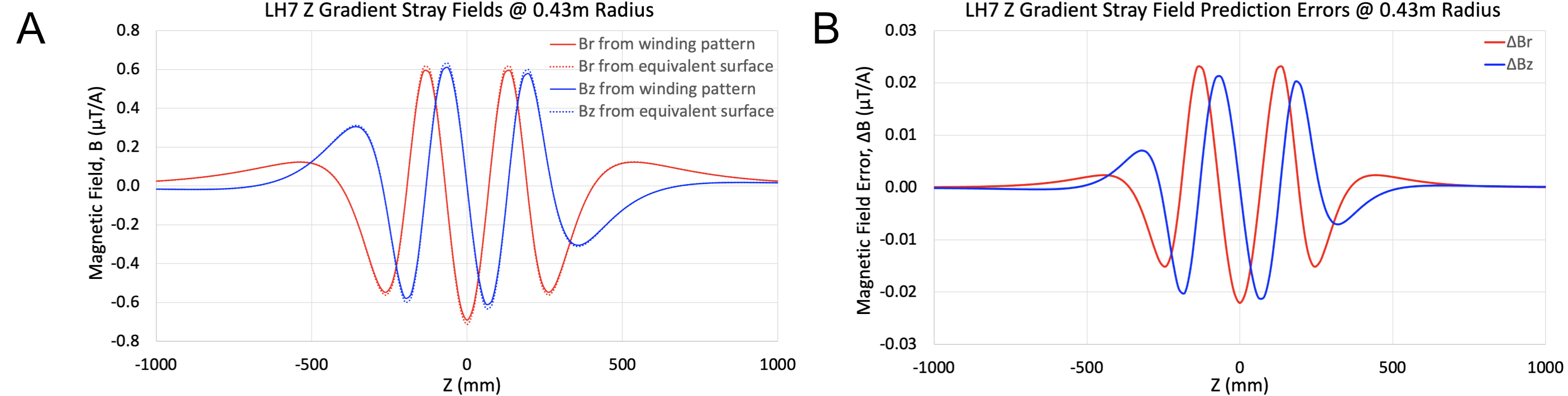
Figure 3. A) Comparison of radial and Z
components of magnetic field, calculated via Biot-Savart from known winding
pattern (solid) or from equivalent current surface (dotted). B) Discrepancy
(error) in radial and Z components of magnetic field between Biot-Savart and
equivalent current surface calculations. Relative field errors are ~3%. Close
match validates ability of equivalent current surface model to reproduce the
actual gradient coil fringe fields.
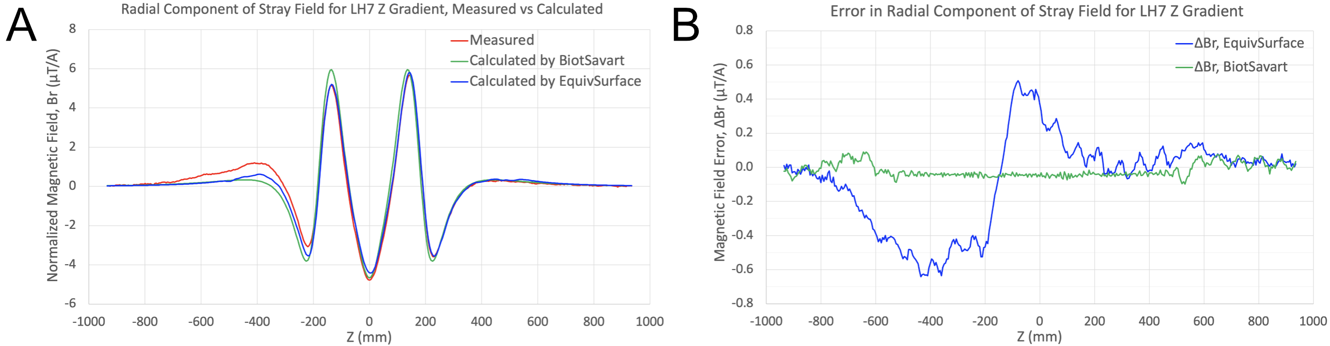
Figure 4. A) Comparison of radial magnetic field component, showing measured (red), Biot-Savart calculation from known winding pattern (green), and ECS calculation (blue). Note that ECSs were fit using only the Z component of measured fields, then used to calculate the radial component. B) Error in radial magnetic field component for Biot-Savart (green) and ECS (blue) calculations using measured fields as ground truth. Large slowly varying errors for ECS profiles are due to lead contamination, smaller higher frequency oscillations are measurement artifact.
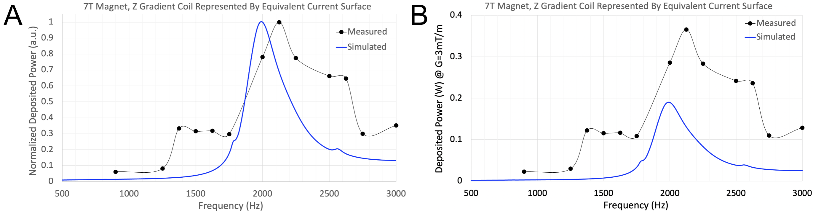
Figure 5. Comparison
of simulated vs measured magnet power deposition vs frequency profiles, using
7T magnet and Z body gradient coil. Simulations use equivalent current surface
to generate fringe fields for input to multi-physics finite-element model. A)
Normalized power vs frequency showing measured (black dots) and simulated (blue
line) profiles. B) Absolute deposited power (for 3mT/m gradient amplitude) vs
frequency showing measured (black dots) and simulated (blue line) profiles.
DOI: https://doi.org/10.58530/2023/1230