1229
Unipolar design of head gradients for eliminating the encoding ambiguity1Institute for Biomedical Engineering, ETH Zurich and University of Zurich, Zurich, Switzerland, 2Philips GmbH Innovative Technologies, Hamburg, Germany, 3Institute for Energy and Process Engineering, ETH Zurich, Zurich, Switzerland, 4Philips AG, Zurich, Switzerland, 5Philips Healthcare, Best, Netherlands, 6Futura Composites BV, Heerhugowaard, Netherlands
Synopsis
Keywords: Gradients, High-Field MRI, Ambiguity
Gradients with a conventional, bipolar design generally face a trade-off between performance, encoding ambiguity, and circumventing the latter by means of RF selectivity. This problem is particularly limiting in cutting-edge brain imaging performed at field strengths ≥ 7T and using high-performance head gradients. To address this issue, the present work proposes to fundamentally eliminate the encoding ambiguity in head gradients by using a unipolar z-gradient design that takes advantage of the signal-free range on one side of the imaging volume. This concept is demonstrated by design of a unipolar high-performance head gradient and simulated 7T imaging with such a system.Introduction
Gradient coils for the z-axis traditionally follow the principle of a Maxwell pair, comprising two sections that generate field of the same spatial structure but opposite polarity1. The two field lobes superimpose to form a bipolar field with a zero in the iso-centre and a surrounding linear range. Outside this range the field reaches maximum excursions, beyond which it gradually drops back to zero, causing ambiguity of gradient encoding. To prevent the related backfolding, the unambiguous range must be made sufficiently long1. However, unambiguous range comes at great expense in terms of gradient performance for given amplifier and PNS constraints2. Therefore, the gradient range required to prevent backfolding is commonly contained by limiting the spatial coverage of RF transmission and detection.While long-established and successful for clinical whole-body systems, this approach to gradient ambiguity is less favourable for cutting-edge brain imaging, which often relies on field strengths of 7T and beyond where RF fields (for 1H) are less contained. At the same time, it demands ever-higher gradient performance, which is increasingly implemented through head-only gradients. These, in turn have intrinsically smaller unambiguous range3-14 and high-field imaging with head gradients has indeed been reported to suffer from backfolding15-18. Maximizing their unambiguous range of head gradients again comes at the expense of performance.
To address this issue, the present work proposes an alternative approach to gradient ambiguity. It takes advantage of the fact that, when imaging the head, ambiguity is of concern only in the trunk and body and thus only on one side of the imaging volume. Gradient encoding without any ambiguity can thus be performed with a unipolar rather than bipolar field, effectively reducing the Maxwell pair to one of its halves. This concept is demonstrated by design of a unipolar head gradient and simulated 7T imaging with such a system. Magnetic and electrical measurements on coils built according to this design confirm feasibility and competitive specifications.
Methods
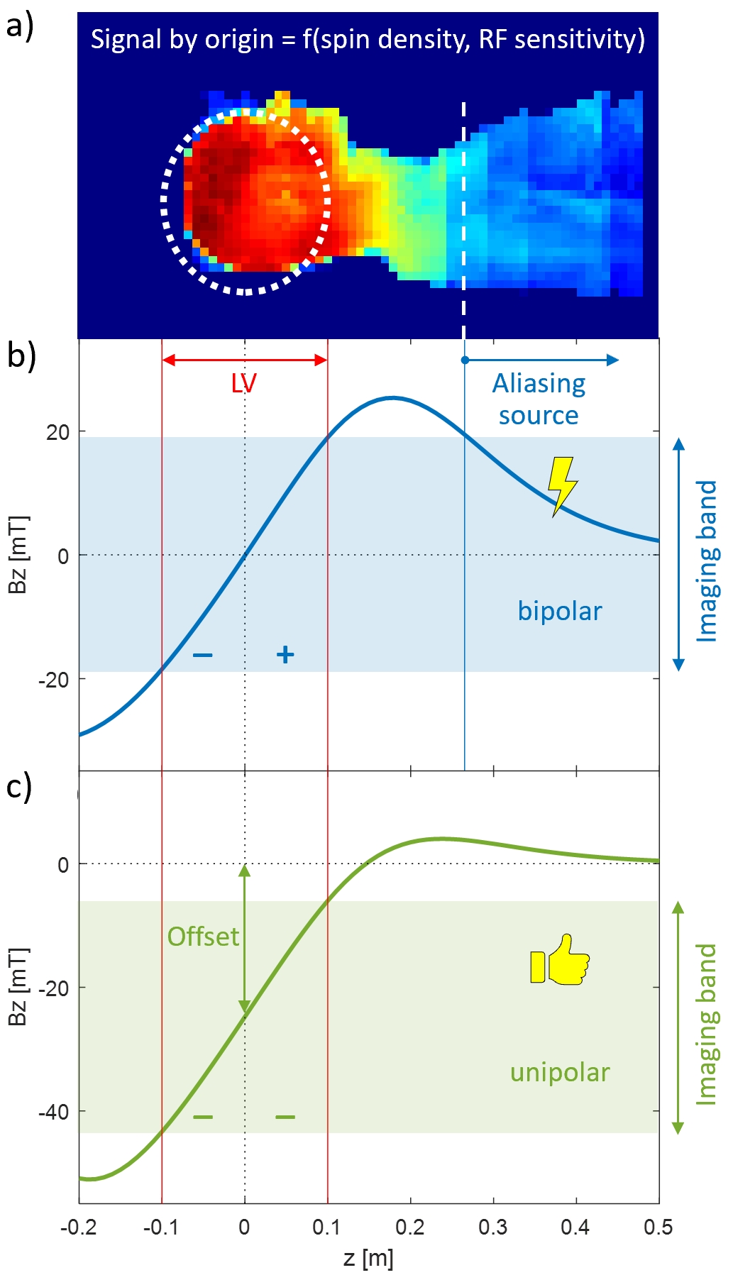
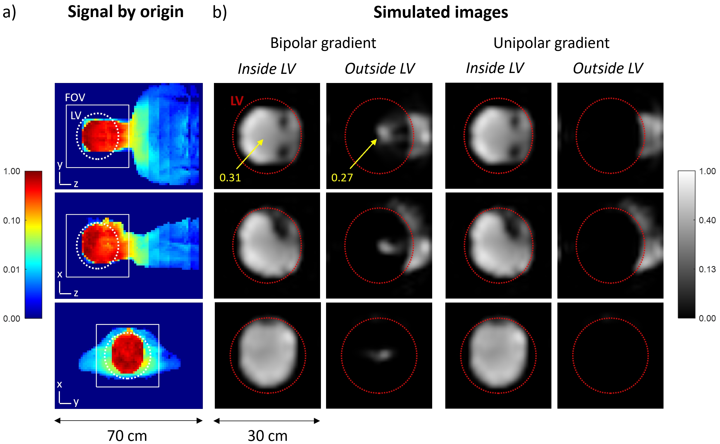
The ambiguity issue and the proposed concept for its solution for a head gradient are illustrated in Figure 1. The ambiguity of a conventional, bipolar design is eliminated by generating a unipolar z-gradient field. This leads to an additional field offset which requires appropriate modulation and demodulation as in off-centre imaging with conventional gradients.To demonstrate the ambiguity effect and support the design procedure, MRI simulations were performed using full 3D signal encoding and image reconstruction with gradient non-linearity correction, based on calculated gradient fields and an experimentally determined signal source (see Figure 1).
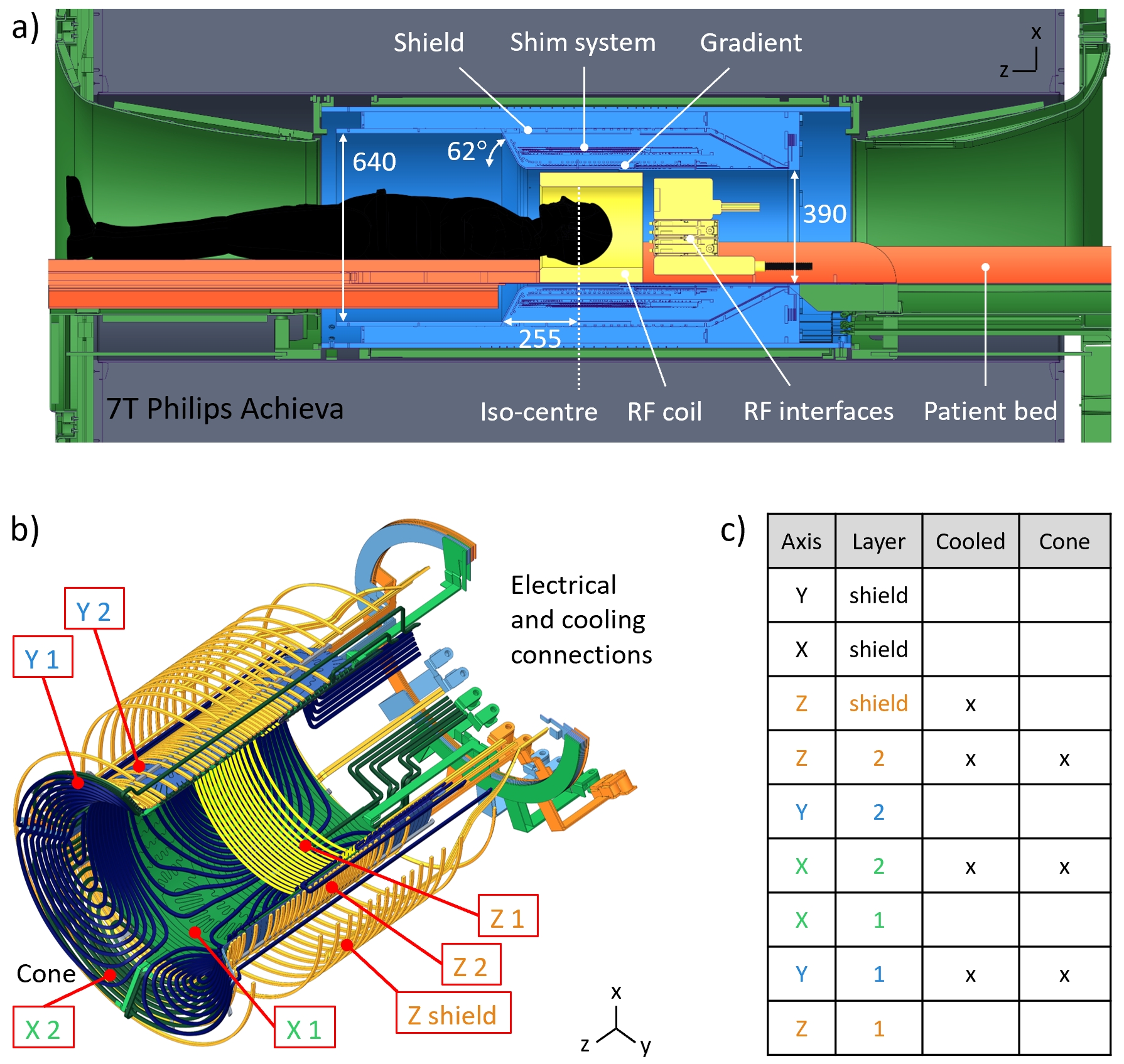
Using the proposed concept, a head gradient was designed for seamless integration into a Philips 7T Achieva system after removal of the body gradient and for operation with a standard environment including a dual-mode amplifier (max. 720 A, 1300 V). The target specifications were: free bore diameter 390 mm, linearity volume (LV) 220x220x200 mm3, nonlinearity £ 20%, strength up to 200 mT/m, slew rate up to 560 mT/m/ms, and duty cycle 100 % (i.e. continuous operation at maximum strength as e.g. required for zero-TE sequences19). The design employs a conical opening to achieve appropriate patient access13. To contain current density, a system of double layers of conductors was chosen and optimised to achieve force, torque, and impedance balancing. Cooling is based on a combination of hollow and solid conductors and monitored with 32 fibre-optic temperature sensors. In addition, a full set of shims up to 3rd order was integrated.
Results
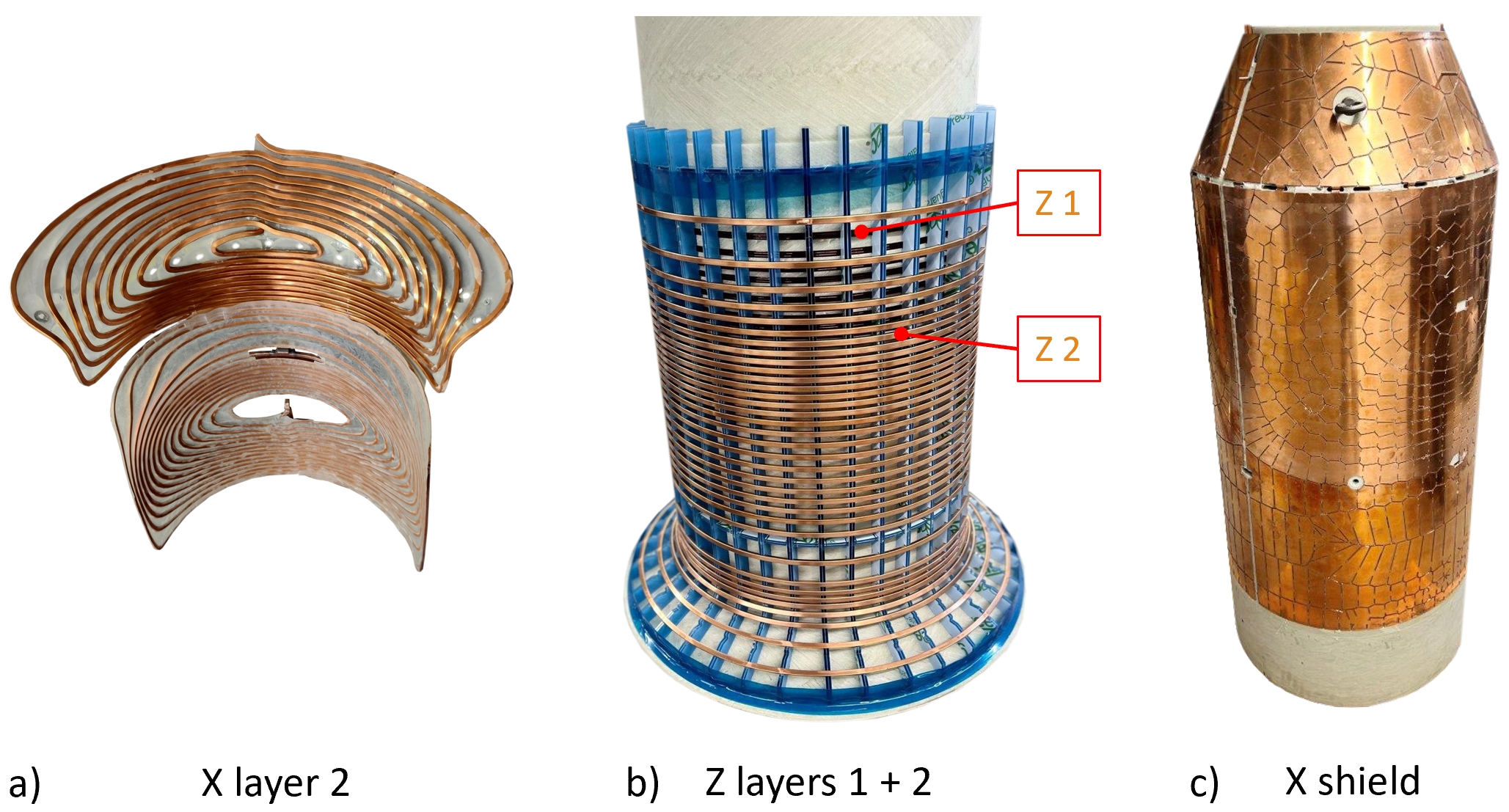
The imaging simulations in Figure 2 demonstrate that with a conventional, bipolar design, signals from the trunk are aliased into the LV with considerable amplitude, in particular in the centre. Using a unipolar gradient, this artefact is eliminated.Figure 3 shows an illustration of geometrical design and optimised layer structure of the unipolar gradient design pursued in this work. The gradient coils according to this design were manufactured (Figure 4).
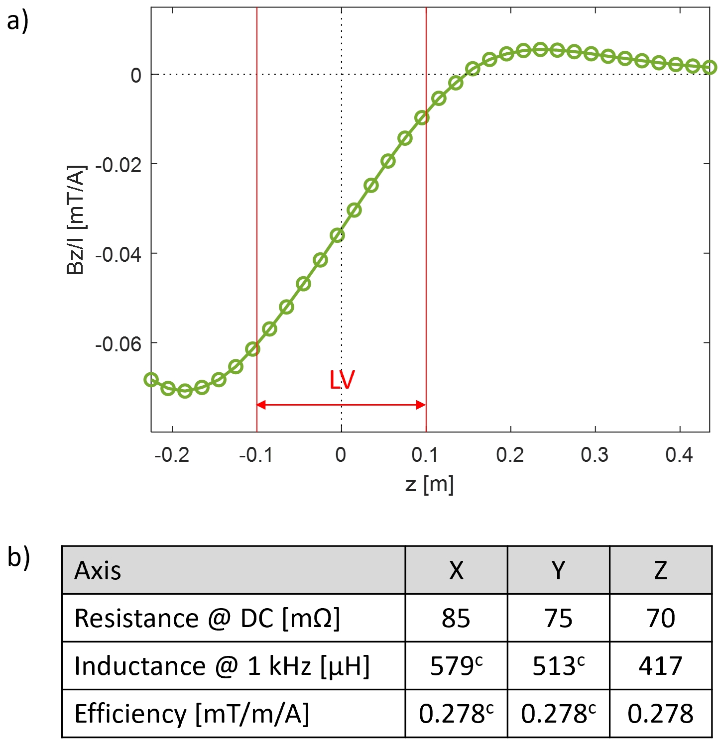
Figure 5 shows results of measurements of electromagnetic properties of the gradient, confirming the targeted unipolar field characteristics and its efficiency.
Discussion
Simulation based on real RF characteristics at 7T has confirmed both the backfolding problem and its solution by a unipolar gradient design. One consequence is greater maximum field strength. That is offset, however, by the fact that the maximum occurs only on one side and well outside the subject where PNS is not an issue. For the neck and shoulders, the unipolar approach is expected to reduce PNS relative to conventional designs (c.f. Figure 1). However, potentially increased PNS at the top of the head needs to be evaluated. As evident from the gradient specifications reached here, the higher field maximum does not prevent clearly competitive performance.Notably, gradient systems with offsets have also been proposed for other purposes such as displacing the slice position20, shifting the LV 6,21, or in fringe field MRI 22.
The reported gradient design has been confirmed by magnetic and electrical measurements on assembled coils. The prospect of full gradient systems based on this sort of design holds promise for advanced neuroimaging that demands high gradient performance. It will make the greatest difference at 7T and beyond where the absence of ambiguity removes a key concern in terms of RF behaviour and instrumentation.
Acknowledgements
No acknowledgement found.References
1. Kimmlingen R. Magnetic field gradients. Magnetic resonance technology: hardware and system component design: The Royal Society of Chemistry; 2016. p 208-263.
2. Hidalgo-Tobon SS. Theory of gradient coil design methods for magnetic resonance imaging. Concept Magn Reson A 2010;36a:223-242.
3. Wong E, Bandettini P, Hyde J. Echo-planar imaging of the human brain using a three axis local gradient coil. In Proceedings of the 11th Annual Meeting of SMRM, Berlin, Germany, 1992. p 105.
4. Petropoulos LS, Lampman DA, Morich MA, Liu H. Wide aperture gradient set (WAGS) for fast and high resolution MRI applications. In Proceedings of the 2nd Annual Meeting of ISMRM, San Francisco, USA, 1994. p 1075.
5. Alsop DC, Connick TJ. Optimization of torque‐balanced asymmetric head gradient coils. Magn Reson Med 1996;35:875-886.
6. Crozier S, Luescher K, Hinds G, Roffmann WU, Doddrell DM. Designs for an asymmetric gradient set and a compact superconducting magnet for neural magnetic resonance imaging. Rev Sci Instrum 1999;70:4062-4066.
7. Chronik BA, Alejski A, Rutt BK. Design and fabrication of a three-axis edge ROU head and neck gradient coil. Magn Reson Med 2000;44:955-963.
8. Kimmlingen R, Eberlein E, Gebhardt M, Hartinger B, Ladebeck R, Lazar R, Reese TG, Riegler J, Schmitt F, Sorensen AG, Wedeen V, Wald LL. An easy to exchange high performance head gradient insert for a 3T whole body MRI system: first results. In Proceedings of the 12th Annual Meeting of ISMRM, Kyoto, Japan, 2004. p.1630.
9. Green D, Pittard S, de Graaf R, Nixon T, Hetherington H. Asymmetric head gradient coil for imaging and spectroscopy at 7T. In Proceedings of the Proc 16 th Annual Meeting ISMRM, Toronto, 2008.
10. Handler WB, Harris CT, Scholl TJ, Parker DL, Goodrich KC, Dalrymple B, Van Sass F, Chronik BA. New head gradient coil design and construction techniques. J Magn Reson Imag 2014;39:1088-1095.
11. Lee SK, Mathieu JB, Graziani D, Piel J, Budesheim E, Fiveland E, Hardy CJ, Tan ET, Amm B, Foo TK, Bernstein MA, Huston J, 3rd, Shu Y, Schenck JF. Peripheral nerve stimulation characteristics of an asymmetric head-only gradient coil compatible with a high-channel-count receiver array. Magn Reson Med 2016;76:1939-1950.
12. Wade TP, Alejski A, McKenzie CA, Rutt BK. Peripheral nerve stimulation thresholds of a high performance insertable head gradient coil. In Proceedings of the 24th Annual Meeting of ISMRM, Singapore, 2016. p.3552.
13. Weiger M, Overweg J, Rösler MB, Froidevaux R, Hennel F, Wilm BJ, Penn A, Sturzenegger U, Schuth W, Mathlener M, Borgo M, Börnert P, Leussler C, Luechinger R, Dietrich BE, Reber J, Brunner DO, Schmid T, Vionnet L, Pruessmann KP. A high-performance gradient insert for rapid and short-T2 imaging at full duty cycle. Magn Reson Med 2018;79:3256-3266.
14. Feinberg DA, Dietz P, Liu C, Setsompop K, Mukherjee P, Wald L, Vu A, Beckett A, Insua IG, Schröder M. Design and Development of a Next-Generation 7T human brain scanner with high-performance gradient coil and dense RF arrays. In Proceedings of the 29th Annual Meeting of ISMRM, 2021.
15. Wald LL, Wiggins GC, Potthast A, Wiggins CJ, Triantafyllou C. Design considerations and coil comparisons for 7 T brain imaging. Appl Magn Reson 2005;29:19.
16. Schmitt F, Potthast A, Stoeckel B, Triantafyllou C, Wiggins CJ, Wiggins G, Wald LL. Aspects of Clinical Imaging at 7 T. In: Robitaille P-M, Berliner L, editors. Ultra High Field Magnetic Resonance Imaging. Boston, MA: Springer US; 2006. p 59-103.
17. Wiggins CJ, Caillat M, Le Bihan D, Schmitt F, Eberlein E. Use of opposed shim currents for infold reduction on a UHF MRI system with head gradient. In Proceedings of the 18th Annual Meeting of ISMRM, Stockholm, Sweden, 2010. p 2339.
18. Massire A. Non-selective Refocusing Pulse Design in Parallel Transmission for Magnetic Resonance Imaging of the Human Brain at Ultra High Field; 2014.
19. Weiger M, Pruessmann KP. MRI with zero echo time. eMagRes. Volume 1. Chichester, United Kingdom: John Wiley & Sons, Ltd; 2012. p 311-322.
20. Hiroshi S. Nuclear magnetic resonance diagnostic apparatus. EP Patent 0108421A2. 1983.
21. Westphal M, Knüttel B, Schmidt H. Gradient coil system. US Patent 5,343,148. 1994.
22. Cho Z-H, Wong JEK. Fringe field MRI. EP Patent 0399789A2. 1990.
Figures