1067
Digital Synthesis at the Coil in a WiFi-enabled Modular Switch Mode RFPA Platform for Gradient-Free Imaging
N Reid Bolding1, Chris Vaughn2, Aria Patel1, Snow Lin1, Andrew Dupuis1, William A Grissom2, and Mark A Griswold1
1Case Western Reserve University, Cleveland, OH, United States, 2Vanderbilt University, Nashville, TN, United States
1Case Western Reserve University, Cleveland, OH, United States, 2Vanderbilt University, Nashville, TN, United States
Synopsis
Keywords: RF Arrays & Systems, Low-Field MRI, Gradient Free Imaging
We present here the development of a wireless flat amplitude 2 MHz radiofrequency transmitter for under $100, focusing on the pulse synthesis stage. We gave special consideration to simplifications that can be made with high speed digital synthesis and switch mode amplifier topology. This is a component of a distributed transmit receive system, meeting the special requirements of gradient free low field quantitative imaging techniques, such as selective encoding through nutation and fingerprinting (SENF).Introduction
When designing lower-cost, higher accessibility scanners, each stage of the system needs to be reevaluated. Significant cost reduction can come through alternative encoding strategies, including methods that use B1 gradients in place of B0 gradients, such as Selective Encoding through Nutation and Fingerprinting (SENF)1. Here we present the development of a wireless flat amplitude 2 MHz radiofrequency (RF) transmitter, focusing on the pulse synthesis stage. We gave special consideration to simplifications that can be made with high speed digital synthesis and switch mode amplifier topology. This becomes a key component of a distributed transmit receive system, meeting the special requirements of gradient free low field quantitative imaging techniques, such as SENF. The design here aims for compact size and low cost to ease the scaling of channel counts. We implemented this RFPA prototype in a modular framework using the current-mode class-D configuration (CMCD)2. In this implementation, the addition of a complex programmable logic device (CPLD) based “synthesis module” and a “feedback module” allow for the synthesis and monitoring of flat amplitude transmit pulses at the coil.Design
In this work, we simplified the synthesis of the pulse by foregoing amplitude modulation in favor of bandwidth and phase modulation, as SENF does not require amplitude modulation. The amplifier is directly controlled by a CPLD operating at a much higher frequency than the pulse frequency (128x). Using the high speed memory access and predictable timing common on low cost CPLDs, the module directly synthesizes a pulse with the phase stability of the reference clock, within 50 ppb for a temperature compensated crystal oscillator for example. For updating the pulse table and reconfiguring the phase locked loop (PLL) or logic on the CPLD, a WiFi microcontroller is connected over an SPI interface to the CPLD. This allows for fully remote configuration of not only the pulse to be transmitted, but the synthesis method itself.On the 1200 lookup table CPLD, a phase table is stored in memory and a counter is implemented, incrementing at the transmit frequency, to index the current phase offset. This offset is added to another counter, incrementing at the PLL generated operating frequency and looping at the transmit frequency. This allows for a dynamic phase offset, updated at the transmit frequency, and occupying minimal space in memory for long duration pulses.
For monitoring performance, debugging transmit issues, and dynamically adapting to loading conditions, we paired the synthesis module with a feedback module to monitor the coil current directly. The feedback module includes a current sense resistor which is in series with the coil. For coil current magnitude, the voltage across the resistor is amplified and rectified, to allow for digitization on the timescale of a pulse rather than the transmit frequency. Coil current phase information is acquired with a comparator across the current sense resistor, sending a digital signal matching the phase and frequency back to the synthesis logic.
Tests and Results
To test pulse stability and noise, feedback capability, and the overall functionality of the transmitter; long term synthesis noise and stability analysis, feedback output fidelity analysis, and pulse transmission fidelity and repeatability analysis are presented here. Synthesis testing involves creating a pulse with a set stable frequency, and analyzing the synthesis module output through time as recorded by a signal analyzer (SA) over 100 averages with a 1 Hz bandwidth to determine primary frequency peak width and side band magnitude. Feedback testing involves driving a 180o phase shift pulse into the feedback module, and analyzing relative output magnitude. Pulse transmission testing involves transmitting the same pulse with a 180o phase shift 3 times and analyzing the distortion during phase shift and timing consistency as recorded by an oscilloscope.Pulse frequency fidelity, feedback capability, and pulse repeatability are shown in figures 2, 3, and 4 respectively. The synthesis module currently conservatively costs $25 in parts and printed circuit boards each, and the feedback modules cost approximately $18. With the cost of the power modules down to approximately $25 due to newly available GaN FET drivers, and the cost of a motherboard at $21. Thus the total cost to build this transmitter is $89.
Conclusions
We show here that a sub-$100 transmit channel for low field MRI B1 encoding, requiring only an existing reference clock source and a transmit gate signal. The module provides remote configuration of stable logic for precise and repeatable pulse synthesis. Using a previously presented CMCD amplifier design, this transmitter is capable of continuous transmission of a 200uT B1+ field from a 10cm loop surface coil. Improvement of the feedback module amplitude feedback fidelity is needed to be useful beyond general debugging purposes. With phase feedback, this platform will allow for the future implementation of real time distortion compensation algorithms using the feedback to the CPLD to improve transmit accuracy. We plan to add wireless clock and gating capability, as well as receive capability in future work.Acknowledgements
No acknowledgement found.References
1 C E Vaughn, M A Griswold, and W A Grissom. MR Barcoding: Gradient-Free MRI Using B1-Selective Parallel Transmission. Proceedings 28th Meeting of the International Society for Magnetic Resonance in Medicine, Virtual, 2020, p. 620.
2 N. R. Bolding, et al., “Low-cost modular RFPA platform for gradient-free quantitative imaging”, Proceedings of the International Society for Magnetic Resonance in Medicine, London, 2022, abstract #0064
Figures
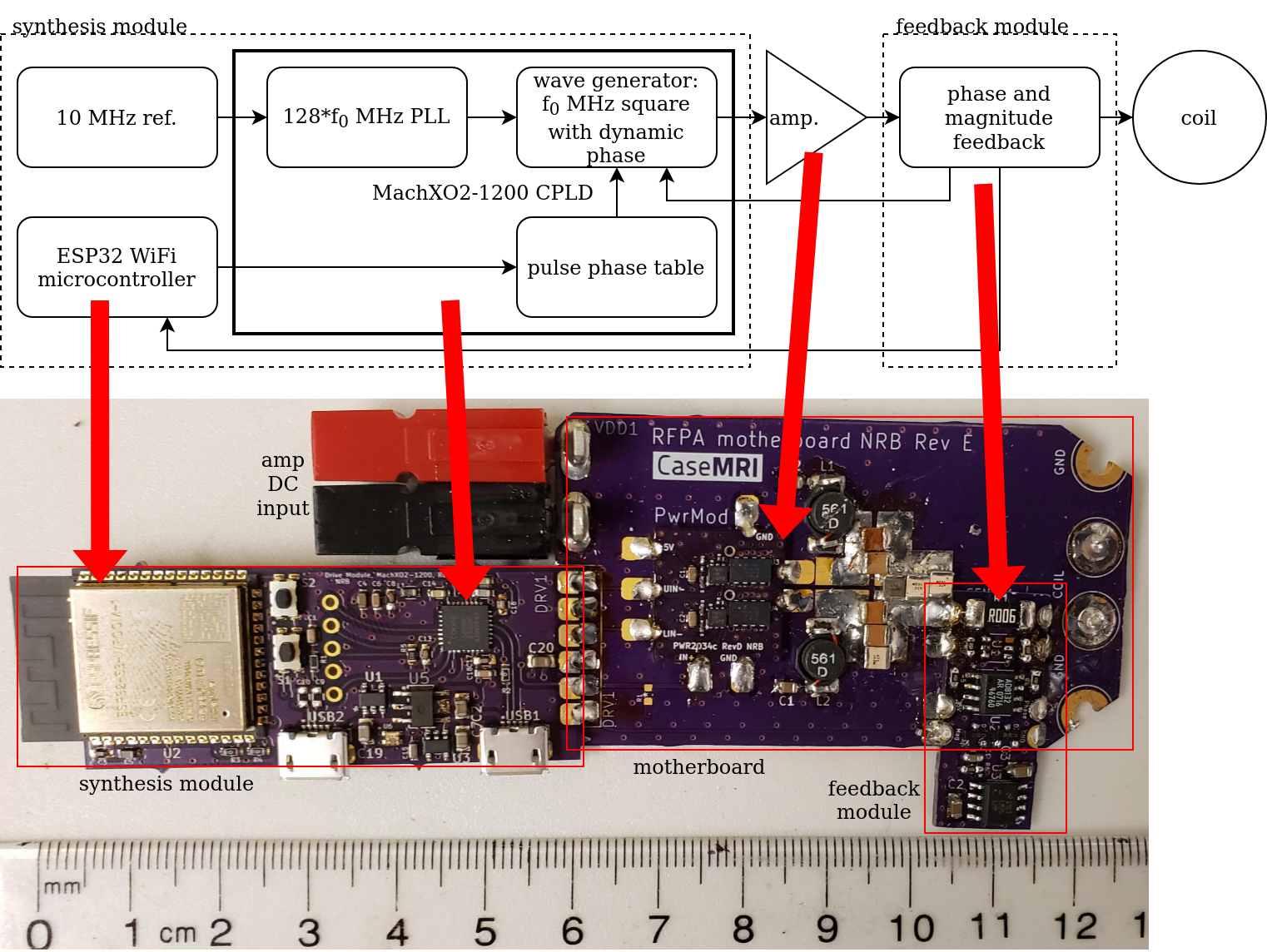
Overview of transmitter design. Above is a functional block diagram, below is a picture of an assembled transmitter, arrows indicate the position of modules named in the block diagram.
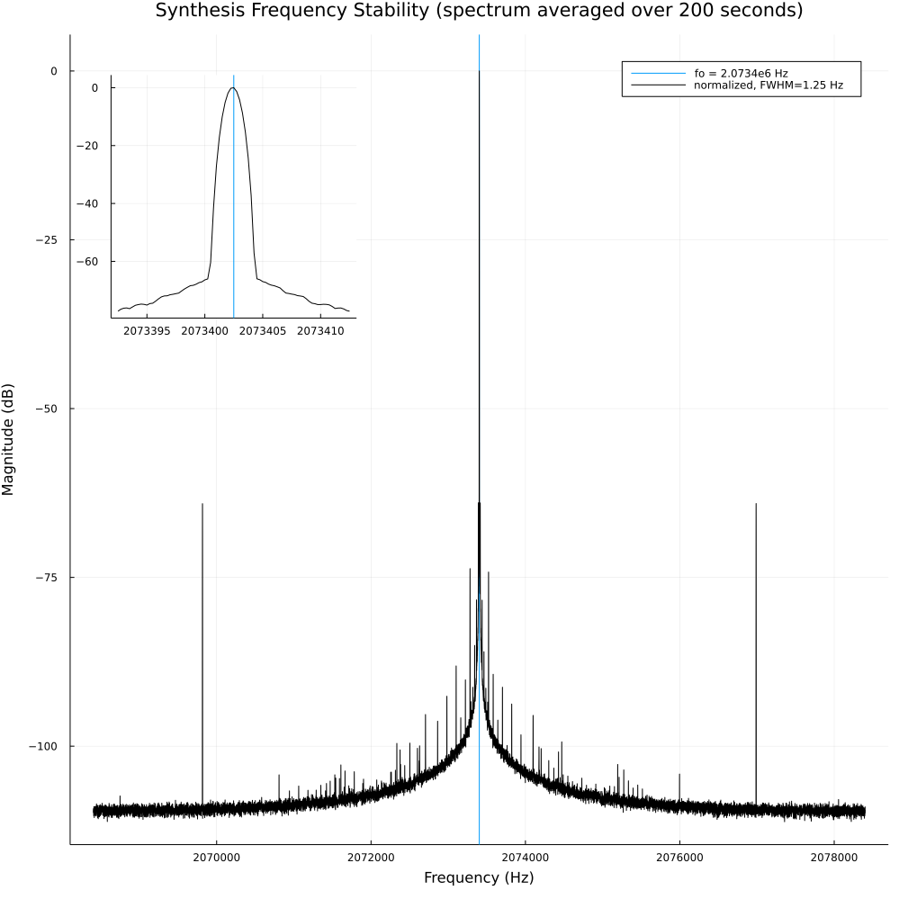
The spectrum of the synthesis module output over a 200 second average,
acquired with a 1 Hz bandwidth. In the
upper left is a zoomed view of the center frequency peak. A full width at half max (FWHM) of 1.25 Hz shows good
stability during the 200 second average on the SA.
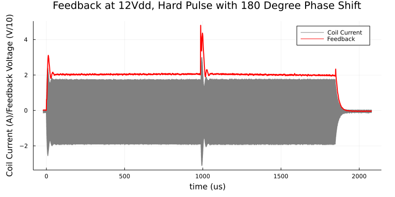
A pulse with a 180 degree phase shifts at a typical power level is
shown in grey, and the feedback module amplitude output voltage after
digital filtering is shown in red. In the normal transmit power range,
the feedback tracks coil current roughly and scales with increased
magnitude. This is useful for debugging. With an improved version of the
feedback module, more accurate amplitude information may assist image
reconstruction.
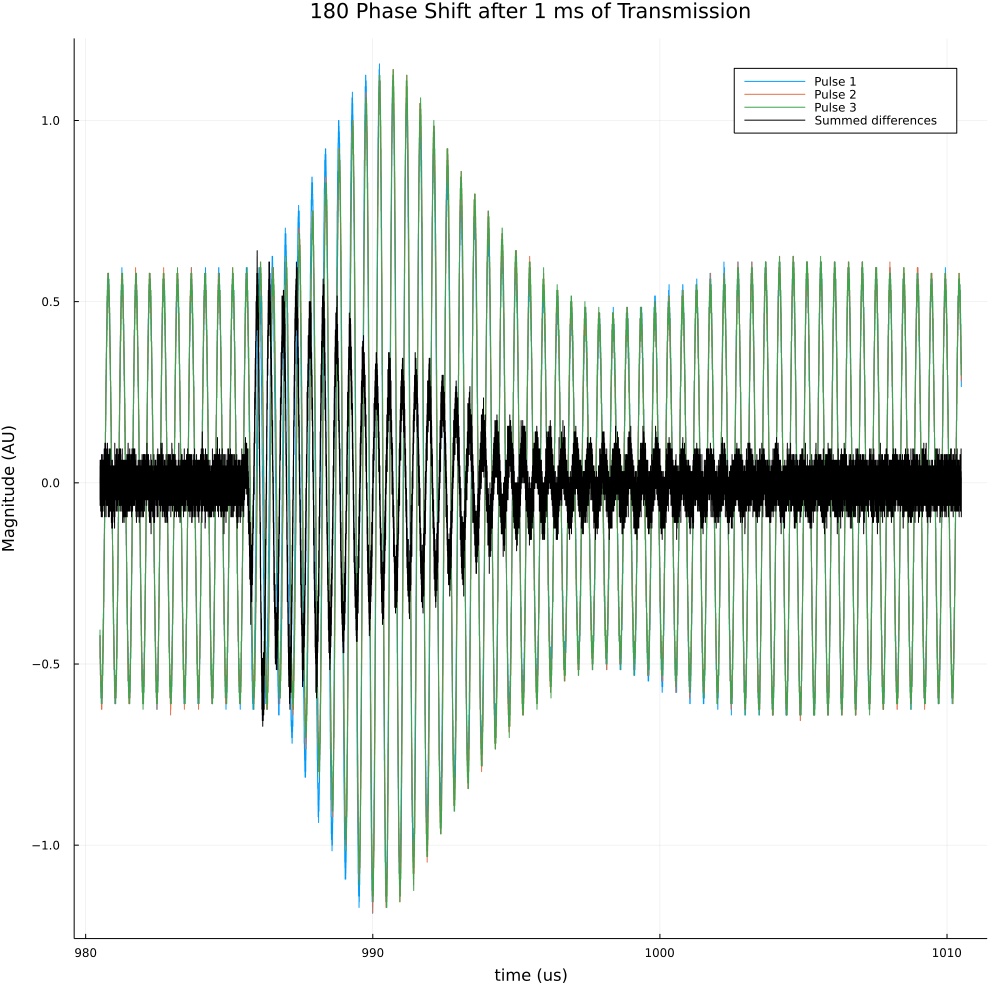
Three consecutive identical pulses are shown here, with the summed
difference between the first and second and first and third shown in
black. During a phase shift there is some inconsistency between pulses,
but the phase shift beginning and settling time remain the same.
DOI: https://doi.org/10.58530/2023/1067